Reference pages

Sunday, June 28, 2015

Tank car “dome” platforms, Part 4

In the previous post in this series, I showed both a prototype photo, and a model under construction, for an insulated, pressurized tank car (ICC 105) for Brea Chemicals of Los Angeles. (You can find that post at this link: http://modelingthesp.blogspot.com/2015/06/more-on-tank-car-dome-platforms-part-3.html .) One part of the project, which ties it to previous modifications I have reported for the Athearn “chemical” tank car, was the use of part of the Atlas platform part, their no. 9170013, to make the walkway alongside the valve bonnet (not an expansion dome, but nevertheless sometimes called a dome).
     At the point I stopped my modeling description in the previous post (link provided above), the bonnet and walkways had been added and primed. Now I needed to add ladders which reached all the way to the upper walks, not merely to the level of the tank handrail, as Athearn provides. Luckily in some recent Athearn “chemical” tank cars, the full-height ladders are included, so I harvested a pair of them for use on this model. They are stamped metal. I simply re-bent them slightly to reach my walkways. In the original white color, they can be seen clearly.


But as was evident in the prototype photo in the previous post (link given above), the tank handrails and ladders were black on the Brea cars, though the walkway was the same silver or silver-gray as the rest of the tank. I handpainted the model that way, as you see here.


     With trucks attached (semi-scale-tread width wheelsets added) and Kadee #158 couplers installed, the model was ready to weather. I wanted to do this in two steps. First, I oversprayed with Dullcote, and weathered the entire car with my usual acrylic tube paints, in wash form; for more on that, you can look at my Reference Pages on weathering, linked through the list at upper right of the blog page. This turned out pretty well. Here’s the car being switched at Shumala at this point.


     The second process I wanted to try was something I had watched Richard Hendrickson do, but had not tried myself. The idea is to mix a really dilute dirty black in plenty of solvent, so that airbrushing this mix from above the model just shadows the top surfaces. Let it dry a few seconds, and decide whether it needs another pass; repeat until satisfied. This technique makes a really nice representation of that “dirt from above” look, getting that area dirtier than the sides. This is especially effective on light-colored cars like this tank car. But my photos do not differ much from what is shown above, so for now I will leave the Brea tank behind. If I have a car which shows the “dirt from above” look well, I will post it later.
Tony Thompson

Thursday, June 25, 2015

A fishing boat for my Santa Rosalia waterfront

On my fictional SP branch, I imagine that the track ends at a town called Santa Rosalia, located at the mouth of the Santa Maria River, and that a few fishing boats work out of there. Accordingly, it would be a nice feature to have such a boat moored at a dock. I have already said a little about my waterfront ideas for Santa Rosalia in a prior post (you can read that initial post at: http://modelingthesp.blogspot.com/2014/07/constructing-santa-rosalia-waters-edge.html ), and more recently showed my progress in modeling along the new waterfront ( http://modelingthesp.blogspot.com/2015/06/santa-rosalia-waters-edge-part-2.html ). A local fishery in turn could support a cannery (though probably not the shipping of much fresh fish). I have already gone ahead and created a model cannery, as described in an earlier post (see it at: http://modelingthesp.blogspot.com/2015/05/kitbashing-santa-rosalia-cannery.html ).
     But if there is to be a fishing boat modeled, the first question a person might ask (and I would say, ought to ask), is what kind of small fishing boats were or are used in this area? As it happens, I found a photo some time ago which clearly shows several such boats, in an image supplied by the Morro Bay (California) Visitor’s Bureau. It of course emphasizes a vivid sunset and the monumental Morro Rock, but that fishing boat in the center foreground is a clear example to work from. Morro Bay is just a few miles up the coast from my supposed location of Santa Rosalia.


     Is Morro Bay relevant? I have spent some time with a very interesting and topical report about the fisheries of central California, entitled “Commercial fishing grounds and their relative importance off the Central Coast of California,” submitted in response to the California Marine Life Protection Act, with principal author Astrid Scholz, then of Ecotrust (it’s 40 pages and is available at the website of the California Department of Fish and Game: http://www.dfg.ca.gov/mlpa/pdfs/agenda_workshop041807_report.pdf ). This 2006 report clearly shows an important fishing ground between Point Buchon on the north, and points Sal and Purissima on the south, with the mouth of the Santa Maria River right in the middle. So the Morro Bay boat shown above would work in the same fishery as would my purported Santa Rosalia boat.
     Other California fishery studies contain fishing boat photos, broadly similar to the one shown above. Here is one example, and like the photo above, the cabin is fairly long.


    Here is another image, a boat with a shorter cabin and a different rig, with a net reel amidships. Naturally there are a wide range of boat details, even in this one fishery.


    I have long admired the fine models of boats offered by Frenchman River Model Works, and seemed to remember that they offer a small boat generally like this. And indeed they do, their kit no. 81. You can see it on their web site: http://www.frenchmanriver.com/Pages/HO/Boats/fishing/fishing.html . I was sufficiently impressed to go ahead and order the kit. The cabin is shorter than many Central California boats, and I could change the cabin in the direction of the Morro Bay boat shown above, but with so many variations among individual boats, I don’t think it will be necessary.
     A couple of days after I placed the order, the kit showed up via Priority Mail, which is excellent service. The kit can be built two ways (cabin forward or cabin aft), as this flyer shows (you can click to enlarge).


As visible in the prototype photos at the top of this post and in other observations, the “cabin forward” orientation, left photo in the model images above, should be my choice.
     I opened up the kit, and immediately found that the parts are very nice, major parts cast in a brown resin, accompanied by some white metal details, all with little flash and fitting well together. I proceeded to put together the basic elements, as you see here, so I could use the model to help me proportion my waterfront elements.


The basic hatches, body details, and cabin are shown unpainted. I am considering  perhaps raising the profile of the bow, after looking at the two California prototype photos above, but haven’t decided. Then, when more details are attached, the plan is to airbrush white or light gray as a base coat. I will show addition of details, along with painting, in a future post.
Tony Thompson


Monday, June 22, 2015

Bay Area Prototype Modelers 2015

On June 20, the annual Bay Area Prototype Modelers (BAPM) meet was held in the multi-purpose room of St. David’s Church in Richmond, California. An all-day affair, the large room with tables for model display was supplemented with a clinic room in which several talks were given. Even though it was a very nice, sunny day outside, about 100 modelers showed up for a pleasant day of viewing and discussing models. Most years, I attend this meet and always enjoy it. The 2012 meet was covered in a prior blog post (you can see it at this link: http://modelingthesp.blogspot.com/2012/06/bapm-bay-area-prototype-modelers-2.html ).
     One of the most interesting displays was presented by Robert Bowdidge, showing how he has produced several SP cars for which there is no commercial source. These included the CS-35A flat car, the F-50-4 flat car, and the W-50-3 Hart convertible ballast car. All were made with a home 3-D printer. The photo below shows his display of completed cars, and he also showed a partially complete car so that the printing process could be appreciated. I tried to take close-up photos of details and did not get very good results, but the models certainly are superbly detailed.


     One of the most striking displays of freight cars at the meet was the group of weathered and graffiti-ed reefers by Tim Keohane. Here is just one example.


     Rickey T. Hall brought quite a few specially-painted locomotives, all beautifully done, and I was especially struck with this group of Bicentennial paint schemes for Santa Fe, Southern Pacific, and Western Pacific.


     Paul Chandler was at the meet, and brought his completely scratchbuilt Burro crane, which is motorized. The photo probably does not do justice to the outstanding quality of detail on this model.


     It is always interesting to see younger modelers at these meets, particularly when they too have brought excellent models. Jonathan Izen was one of those at this meet, and brought two really nice models of Richmond Pacific motive power (from the roof of the building we were in, you could probably see the RP’s trackage). This SW1200 was formerly MoPac 1268. Even the cab-side logo was crisp and readable.


     Nearby was another outstanding group of models, these by Henry Baez. Among my favorites in this group was the flat car loads. In this photo (you can click to enlarge), the hold-down clamps are beautifully modeled.


     As I often do, I brought an entire SP train of 15 freight cars, pulled by a Consolidation and trailed by a cupola caboose. Here is an overview of it.

     I always enjoy this kind of RPM meet, because there is just an amazing amount of conversation among the different tables, modelers asking things like “how did you do that” or “what’s the prototype” or “is it a kitbash” and so on. Looking around the room, you can watch everyone appreciating what they see, and in most cases learning a few things at the same time. As hobby experiences go, it is one of the most positive ones I know of.
Tony Thompson

Friday, June 19, 2015

More on tank car “dome” platforms, Part 3

I have posted a description of my efforts to create a properly sized platform on an Athearn high-pressure tank car, surrounding the valve bonnet (it is sometimes called a “dome” but is not an expansion dome). That post can be found at: http://modelingthesp.blogspot.com/2015/05/another-approach-to-tank-car-platforms.html . My changes used an Atlas tank car part. In this post, I show another way to improve an Athearn “chemical” tank car, also using the same Atlas part.
     The part is Atlas no. 9170013, and to repeat a photo from the previous post, looks like this.


In the previous post, I used the leftmost part of this molding (the entire left handrail  plus the space between the two handrails), and mated it with the same part of a second molding (reversed) to make a full platform with handrails. (If this description is confusing, please see the post cited at the top of this post, as it shows the process.) What was left over was the righthand side of the Atlas part in the photo above (that is, the entire handrail section at right). I use the grid walkway part of that section in the present post as raw material for a “dome” walk.
     But before I begin with the modeling, let me show what prototype I am aiming at. It is a General American car leased to Brea Chemicals, which was part of the Chemicals Division of Union Oil Company, with a plant manufacturing ammonia and other fertilizer constituents. The plant was at Brea, California, thus the name. This photo is from Richard Hendrickson’s collection, but I don’t know photographer, date, or location.


Note that the car has only a short walkway alongside the valve bonnet (a photo of a different Brea car shows a longer walkway), and has a ladder reaching all the way up to the walkway. It’s possible that the ladder was only on this side, but by the time this car was built in 1948, the usual practice was to have ladders and walks on both sides. It’s evident that the tank handrail and ladder are painted black.
     Here is an Athearn kit (custom decorated) that I have had for some time, with the bonnet sawn off and the site filed flat, some paint touch-up, and addition of the bottom part of the Frank Hodina bonnet (see prior post). Also visible are two pieces of white styrene, which are pieces of scale 4 x 4-inch strip, cut in half the long way, diagonally (making a triangular cross-section), then glued down on the wide side, so that the upper surface of the strip is close to horizontal.


The purpose of these little white pieces is to support the walkways which go alongside the bonnet.
     The two walkways are cut from the unused part of the Atlas platform shown at the top of this post. Here they are, applied atop those styrene strips, and with the Hodina bonnet completed.


     During the work shown above, I was also fixing the Athearn underframe, in the way that I normally do. Removing the three sets of bottom outlet details, drilling the coupler pocket post and cover so they could be tapped 2-56, then cutting off the pocket covers so they become separate pieces, are all essential here. Also, the vertical-wheel handbrake arrangement furnished by Athearn, a rare prototype arrangement for tank cars, is removed and a brake staff of 0.019-inch brass wire installed. I usually add a Tichy tank car brake wheel, as I did here.
     The Athearn bottom sheet, designed for their three-compartment car, also needs cleaning up. All rivets on this part should be removed, though I sometimes leave the ones on the center anchor. All other rivets definitely go. The bottom sheet in my custom-deocrated kit is black, and the prototype photo above shows that it should be black, though the prototype one is located very low on the tank. I chose not to try and reproduce that location.
     I could now assemble bottom sheet to tank, and underframe to tank body, and did so. Here is the model at this point, with primer on the bonnet and walkways. You can just see the brake wheel on the near end (click to enlarge if you wish).


I will show how I handled the ladders, and will complete the rest of the model, including weathering, in an upcoming post.
Tony Thompson

Tuesday, June 16, 2015

The East Shumala stock pen, Part 2

In Part 1 of this thread, I talked about stock pens in a general way, and provided some citations to sources of information about the livestock business. I also said a little about the starting point for my stock facility, the old Associated Hobby (AHM) kit. You can read that previous post at this link: http://modelingthesp.blogspot.com/2015/03/a-stock-pen-for-east-shumala.html .
     As I stated in the first post, I wanted to expand the size of the facility by adding another pen, which meant building some additional fencing. I also needed to correct the failure of some kit parts to have horizontal boards on both sides, which the prototype did for any fencing which had animal movement on both sides. As part of the facility, I also wanted to provide a water supply and an office.
     The fencing part of the problem is fairly easy. Using Evergreen styrene, I added horizontal boards of scale 2 x 8-inch strip, and posts of scale 4 x 4-inch strip. Here, from top to bottom, are an unmodified original AHM piece (top), two of the new fencing units (middle), and an AHM section with doubled side boards added (bottom).


Once all fence modifications or new construction was complete, both sides of all parts were airbrushed with Star Brand “Seasoned Brown Wood” color, STR-11.
     The AHM kit included a “ground”piece to which fences and buildings could be attached. I began by painting it with a mixture of acrylic tube paints, Raw Umber and Yellow Ochre. Then I assembled the fencing to the base by following slots in the base, and gluing my fence segments into the slots.
     With this part of the job completed, I decided to see how it looks on the layout, even though my expansion section wasn’t finished yet. Here is a photo.


That’s the Phelan & Taylor packing house in the background, and Pismo Dunes Road in the foreground.
     In the photo above, you see additional structures, in addition to the kit fences. Accessory buildings include the water tank, which was probably no longer water-filled once town water was available, modeled as a familiar California structure, a tankhouse. In two previous posts, I described the background and modeling of these structures, starting with this link: http://modelingthesp.blogspot.com/2015/04/building-california-tankhouse.html . After that introductory post, I completed the modeling, at: http://modelingthesp.blogspot.com/2015/05/building-california-tankhouse-part-2.html .
     Also visible in the photo above, at the right of the pens, is an office, a small brick structure left over from another kit. It is about the right size, but does not seem to me to look right as a small office for this stock facility. I would expect such an office to be a simple frame building, and one with a lesser roof pitch, so will have to put together such a structure. This is of course quite easy with styrene sheet and commercial windows. I will show it in the following post.
     I have also started work on my expansion pen, which will be located at the right of the kit pens as seen in the photo above. I began with a piece of 0.040-inch thick styrene about the same size as the kit base, and added a water trough to match those in the AHM kit. This additional base piece will support the added fencing for the third (expansion) pen. The new base was painted with the same acrylic colors, then fencing was applied. I will continue with this model in a future post.
Tony Thompson

Saturday, June 13, 2015

Waybills, Part 41: overlay bills

I have described in previous posts the idea of “overlay” or partial waybills, which permit different loads to be assigned to a particular car without a new waybill. You can read the original post’s discussion on that idea at this link: http://modelingthesp.blogspot.com/2011/08/waybills-10.html . I developed the idea further for use with Empty Car Bills, which adds further flexibility to car handling and movement, in a subsequent post, which is here: http://modelingthesp.blogspot.com/2012/02/waybills-19-confiscation.html . I have also called these “short” bills in some posts, if you want to use the search box to find further discussion.
     If these ideas have been previously described, why am I bringing them up again? The main reason is that until recently, I had not seriously implemented these ideas for my own layout. The examples in the posts cited above are for Otis McGee’s layout, which differs in having largely bridge traffic and relatively little on-line industrial switching. I wanted to see how well they would work on my own layout, which is entirely dominated by switching.
     The basic idea, for me or for Otis, is simple, but it has some subtle points, along with some obvious things to watch. Since the idea is to use a full waybill as backing, and that waybill shows the originating railroad along with car initials and number, the overlay bill works much the best for loads originating on the home railroad of the layout, in my case Southern Pacific. Moreover, it should be obvious that this idea can only be applied to free-running cars like box cars, or to cars which always have the same purpose, like refrigerator cars. Here is an example. This way, a particular car does not always head off to the same destination; and when there are multiple refrigerated shippers in one town, as in my layout location of Ballard, a particular car will not even always be sent to the same shipper.


     The same can obviously apply to box cars, as in these two outbound loads from Pacific Chemical Repackaging in Ballard:


And here again, the empty box car arriving in Ballard can be directed to any industry which loads such cars outbound.
     This same idea can work for other free-running cars like gondolas and flat cars, though I don’t have much in the way of industries shipping in those cars. Lastly, if there is more than one originating industry on an off-line railroad (the Northern Pacific, let’s say) for a particular car type like box cars, this method can even work (in my case) for non-SP waybills. Here’s an example from the Pennsylvania Railroad, of box cars headed to two different Ballard industries:


     This enables a particular car to take different inbound jobs as well as different outbound jobs, a helpful way to avoid the same problem mentioned above, the same car always with the same load or job. And it may be obvious, but in case it isn’t, let me say that numbers of these “overlay” bills can be made up for a single shipper, representing multiple shipment options. All four of my packing houses have ten or so overlay bills each. And of course I have lots of PFE and other reefer waybills with which these overlays can be paired.
     Incidentally, let me make the further point in passing, that many modelers, devising a waybill inbound to an SP location from the PRR, would automatically choose a PRR box car, or an eastern box car. In fact, under car service rules, the PRR yardmaster would be attempting to find SP or at least Western railroads for his load to California. Of course eastern or PRR cars might get this load, too, but not every time.
     These ideas clearly are not practical for foreign railroads which aren’t very big shippers to my layout area, or don’t load all the same kinds of cars, nor of course can they work for specially equipped cars in most cases. But they do work for some large groups of cars, as I showed above. I am happy to see them working on my Santa Rosalia Branch layout.
Tony Thompson
Wednesday, June 10, 2015

Richard Hendrickson’s lumber loads

Awhile back, I showed photos of several dramatic freight car loads built by Richard Hendrickson, loads which required two or more cars to transport (see it at: http://modelingthesp.blogspot.com/2015/03/richard-hendricksons-multi-car-loads.html ). Richard was obviously intrigued by those kinds of loads and thus built a number of them. He also was intrigued by lumber loads, and built several different kinds, which I want to show in this post. (You can click on any of these images to enlarge them.)
     After packing up all of Richard’s freight cars, I photographed almost every one, before distributing most of them to his many friends. Thus I have the photos to show, even of cars I no longer have. One thing to realize: he almost always glued loads onto or into cars, partly so he could freely model tie-down or other attachment methods, without having to worry about removability. All the ones shown here are glued on. For his diorama-style layout design, there was to have been little or no switching, so there was no need for removable loads.
     I will begin with one of his oldest models of a lumber load, a converted Athearn 40-foot flat car with upgraded details. It is lettered for Great Northern 69534, the prototype for which is indeed quite similar to the Athearn model.


The lumber load here is a triple stack, a common practice which is seen in prototype photos. The load is entirely built board-by-board, though it is hollow.
     A similar load in terms of lumber size is this one, on a Tichy 40-foot flat car. The Nashville, Chattanooga & St. Louis is one of the prototypes for which the Tichy car is an almost exact match, thus this choice of NC&StL 70153 lettering.


This load also is board-by-board, and is hollow.
     Sometimes prototype photos do show much larger timbers being moved on flat cars, and Richard modeled an example, in this case using one of the WestRail models from his own company. It is a 53-foot, 6-inch car, lettered Northern Pacific 62148.


     Another interesting variation is creosoted lumber, such as bridge timbers or other kinds of uses, modeled here on an SL-SF flat car (modified from an Athearn 40-foot model). Lettering is SL-SF 95470. In this case, Richard applied cast brass stake pockets on the car to replace the rather oversize pockets molded by Athearn, and as you can see, was able to represent side stakes extending through these pockets. These same pockets were provided in the WestRail flat car kits.


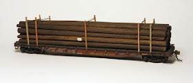
     Finally, not really lumber but certainly forest products, is this striking load of creosoted poles, again on one of Richard’s own WestRail models. This too is  a 53-foot, 6-inch car, numbered UP 57255. Here, he chose to use very fine wire for the cross-ties on the stakes, something often seen on the prototype but rarely modeled. The poles are sanded-down chopsticks.


     The variety of these loads, and the fine modeling achieved to represent them, including the accurate load securements, are another testimony to Richard Hendrickson’s skills. They have given me modeling ideas, and I hope you may have a few also.
Tony Thompson

Sunday, June 7, 2015

Santa Rosalia — the water’s edge, Part 2

My first post on this topic gave some general information about the goals of this part of the layout, and something about the approach I am taking to modeling a small area of waterfront at Santa Rosalia (you can read it at: http://modelingthesp.blogspot.com/2014/07/constructing-santa-rosalia-waters-edge.html ). In the present post, I describe work on creating the water area alongside my sea wall.
     First, the sea wall needed to be blended with the surrounding layout surface. I used Sculptamold for most of this, refined with taxidermists’ paper mache (Brandt’s). Second, I formed a fillet at the interface between the vertical wall of the room, and the horizontal surface where the water will be. This follows the approach I explained in an earlier post (you can read it at: http://modelingthesp.blogspot.com/2015/02/that-layout-backdrop-interface.html ). Once the fillets were sanded smooth, I coated the flat bottom of the water area with shellac. I like this finish for sealing wood surfaces. In its initial state, then, here is that area with fillets built:


Around the seawall area, you can see the approaching slope on the left, built up with paper mache of my two kinds.
     My next step was to prepare the seawall edges. As I showed in the previous post (link provided at the top of this post), Frenchman River Model Works sells a set of very nice resin castings of rows of pilings, their part no. 1573. One package of these contains three pieces, each 4-7/8 inches long, enough for my entire water’s edge. I did have to shorten the height of the pilings by 1/8 inch from the bottom of each piece to fit the height of the seawall I had built. I simply sawed this amount off with a razor saw. The piling sections were primed with a light gray.
     I also decided to represent the wharf along the seawall as wood planking, and used Evergreen no. 4100 V-groove sheet (this material has 0.100-inch spacing, which represents about 9-inch planks). I distressed the Evergreen pieces using a scriber, then used very coarse garnet paper to roughen the surface.


Here you can see the styrene “planking” merely laid in place — it still needs to be detailed and painted. By the way, at the rear you can see how the vertical room corner is coved.
     I now added heavy timbers along the edge of the dock pieces you see above, on which to mount mooring cleats, bitts, etc. These timbers were made using Evergreen styrene strip, 6 x 10 scale inches. These too were gently roughened with coarse garnet paper. Then I added styrene NBW castings to the edge planks, taken from an old Kemtron set, X-198. Next I primed these strips with the same light gray color as the pilings.
     The color I wanted to try on these pilings and wharf is a Star Brand color, “Seasoned Brown Wood” (STR-11), which has a very realistic look, though fairly dark. The color can go directly onto another piece of the scene, a short Central Valley stairway (taken from CV set 1602, “Steps and Ladders”), leading up from vehicle parking onto the dockside. Once painted, these were weathered with acrylic washes to lighten the color somewhat and add some gray.
     Here is how one of the piling sections looked, with the tops toward the camera. Note the slight irregularity in height and spacing of the individual piles. I think this is a really nice product.


     But before installing all this dock detailing, I needed to paint the “water” surface a suitable color, and deal with the sky-water interface, along with the lower edge of the sky on the bounding walls. My idea for the sky was to depict the familiar marine layer of cloud, so common on this coast, as though it might be lying some ways offshore. Adding a fog bank this way also would help avoid the problem of depicting the distant sea surface.
     For water, I used a light green, with lots of Neutral Gray, as seawater typically looks inshore. Once colored to my satisfaction, I can use Gloss Medium to give it a shiny water surface. One advantage to this method of representing water is that it can be cleaned with a damp cloth and, if necessary, recoated easily. My experience with modeled water made with cast clear resin has been that maintaining it is not so convenient.
     For my fog bank, I used primarily Titanium White acrylic tube paint, with a little Neutral Gray, to create the look of the marine cloud layers that we often see in the Bay Area this time of year and traditionally call “fog” even when it is in the form of overhead clouds. Here is how it looked at this point:


      Once I have the Gloss Medium on the water, I can install all my dock pieces and continue with scenery treatment on the shore side. I will describe those steps in a future post.
Tony Thompson

Thursday, June 4, 2015

How I set up an operating session

I received an interesting query by e-mail after my recent post about the first “public” operating sessions on my layout in its present form; you can read that post at this link: http://modelingthesp.blogspot.com/2015/05/a-public-operating-session.html . The question involved some of the details in setting up the sessions, and I replied with a link to a post I wrote some time back, covering more broadly many of the issues for layouts in general (see it at: http://modelingthesp.blogspot.com/2013/09/setting-up-operating-session.html ). But the questioner had more specific concerns about waybills and movement of freight cars on my layout, thus this post.
     I have long believed in, and have tried to implement, car movements derived from an idea called “demand-based car flow,” and wrote three blog posts about it (the core post is probably the second in the series, which can be found at: http://modelingthesp.blogspot.com/2011/11/operations-demand-based-car-flow-2.html ). Over a series of sessions when I operate the layout by myself, this works fine. But it can result in irregular traffic flows, sometimes considerably so, and for operating sessions with guests, I modify the layout status to get a more “average” traffic flow. Here’s how I do that — and you could do it this way even if you have no car-flow system at all.
     My first step to set up a guest session is to walk around the layout and see what freight cars are in what locations, and consider the next moves of each, that is, whether they are loaded or empty, and how their movement will affect the totality of switching moves in that town. I sometimes carry a pad of paper to make notes, and gradually I build up a picture of what all would or could transpire in a session.
     Then I look at my staging table and my open shelves for car storage (the latter were described and shown in a photograph contained in a prior post: http://modelingthesp.blogspot.com/2011/12/operations-car-flow-and-car-storage.html ) to see what options I have readily available for new cars arriving on the layout. These may or may not be cars that would be chosen from my car-flow schedule. Many of them can become inbound cars to the industrial spurs which I have just surveyed to identify outbound cars which would leave those industries. Again, especially if I am using a pad of paper, I can add these to my picture of the possible car movements.
     At this point, I am imagining car movements such as spotting an empty wine tank car for loading, at my winery in Ballard, as in this view:


The same kind of imaginary plan of car movement is evaluated at every industry in each town. As I said, most of what I have been describing has come about from my car-flow schedule, but is being considered for modification to suit visiting operators.
     Next I look at waybills for all the candidate new cars, especially the ones which would become the new inbound cars. They may already have waybills made out that would be suitable for what I need, or sometimes they don’t. If not, of course, the right waybills are quick and easy to create and print out for use in the session. [In this blog I have written numerous posts about waybill usage, and you can search for them using the search box in the upper right corner of the blog page, with a search term like “waybills” or something more specific.]
     These inbound cars, by the way, can be staged onto the layout in advance, where needed, or can be placed in the Guadalupe Local so that they arrive at Shumala in the middle of the operating session.
     Usually I would then make sure I have everything covered, by making a quick list of the car movements in the session, to make sure there are no omissions, duplications, or other sources of confusion. But if things seem straightforward, with movements that I am familiar with in most cases, I would not bother with a list.
     Finally, I would sketch up a list of the agent messages needed for each town, based on what I have put together for car movements. Though not absolutely necessary for most movements, they do help crews with some information, as I described in my previous blog post (see that post at: http://modelingthesp.blogspot.com/2015/06/operating-with-agent-messages.html ).
     Then my hope is that each operating crew person can figure out the switching to be done, and proceed to do it, as Ray DeBlieck is doing at Shumala in this photo.


     As you can see, the entire set-up process does not take a lot of time, though making lists, agent messages, and (if needed) making more waybills may take some additional time to complete. So far my set-ups have been successful in laying out duties for crews, so I guess my process works.
Tony Thompson

Monday, June 1, 2015

Operating with agent messages

I have mentioned in previous posts that in many cases, railroad agents provided local switch crews with written messages to help direct their work. More commonly, I am sure, the communication was simply verbal. With both agent and crew doing the same jobs day after day, even the most abbreviated conversation would readily convey all that needed to be said. But if the agent were not on duty, a written message would substitute.
     My first post on this topic was fairly general, about the agent’s role (you can see it at: http://modelingthesp.blogspot.com/2011/10/operations-role-of-agent.html ), but was followed by something specific about the use of bill boxes for communicating the written messages. The latter post can be viewed at: http://modelingthesp.blogspot.com/2012/03/bill-box.html , and some prototype agent’s messages were included there. For the case of the SP in particular, I have described the use of blank forms of various kinds by agents for all kinds of messages, especially telegram forms (which by the 1950s were abundant and not often used as intended). That post is at this link: http://modelingthesp.blogspot.com/2012/08/internal-sp-communications.html .
     Waybill preparation has been described in several prior posts, including this one ( http://modelingthesp.blogspot.com/2014/07/waybills-part-33-more-on-role-of-agent.html ), and the waybill of course was part of the communication to switch crews. A conductor stepping into a depot to see the agent would receive fresh waybills for outbound loads which were to be picked up, along with Empty Car Bills for empties to pick up, and the conductor would deliver to the agent waybills for inbound loads the crew was going to spot or had already spotted. What the agent might have to convey verbally or in writing, was where to direct arriving empty cars (which were normally moved with paperwork only identifying a town destination), along with any special instructions, such as refrigerator cars to pre-ice.
     My own approach to using these messages was shown in a preliminary way in a post about a practice operating session, which I described in this post: http://modelingthesp.blogspot.com/2015/04/a-practice-operating-session.html . That practice session was informative for me, and I modified and extended the messages used then, for the full sessions conducted in my “public” sessions that followed. I described those sessions in a post soon afterward. You can find it at: http://modelingthesp.blogspot.com/2015/05/a-public-operating-session.html .
     This post is about the evolved messages I used. Drawing on the prototype messages shown in the earlier posts, I concentrated on identifying empty cars for crews to pick up, empty as well as loaded refrigerator cars needing icing, and any off-spot cars. Waybills for loaded reefers contain icing instructions, but a waybill is not made up until a car is loaded or about to be loaded, so the crew needs direction on icing if needed prior to loading (called “pre-icing”).
     Here is the opening message to the crew working Shumala at the beginning of the session.


As mentioned, this is on an SP telegram blank. For ease in reading the content, which may be a little small on the full message (above), here it is by itself.


The font used here, incidentally, is one called “Old Typewriter.”
     The empty car directions are not absolutely necessary, as the agent could hand the crew the filled-out Empty Car Bills for these cars, but I noted in reading the prototype messages that in several cases, agents did inform crews this way about empties to pick up. “Initial icing” is the first icing of a car after loading.
     The same kind of message was provided at the start of the session for the crew starting work at Santa Rosalia. For simplicity, I made one message, from the Ballard agent, directing work at both Ballard and Santa Rosalia, but in future I will probably issue separate messages upon crew arrival at the respective depots. Here is the content of that message.


     The pattern is much like the Shumala agent’s message, with the addition of a single off-spot car which needed to be spotted. The crew could be handed the waybill for this car when they get the agent’s message.
     For both messages, if you wish to figure out what the crew was expected to do, it might be helpful to look at my schematic town maps. The crew had these in the timetables they were issued. Construction of my timetable was described in my Model Railroad Hobbyist column, October 2014, and in a blog post, at: http://modelingthesp.blogspot.com/2014/10/my-column-on-timetable-construction.html .
     All four crews who operated here told me that the messages were clear and helpful about the “missing information.” The messages supplemented the waybills for loaded cars to deliver, which the crews also had, so those cars are not included in the agent’s messages. There were also cars at various locations which did not need to be moved, and for which crews had no waybill, Empty Car Bill, or mention in the agent’s message, and in that case, the cars were where they were supposed to be, no action required.
     I will continue to use, and likely to refine, my agent’s messages for switch crews. It reflects the prototype reality of the role of the agent, and seems to work all right in an operating session.
Tony Thompson