Recently it seems like I keep coming back to the same troublesome switches, the two new ones I installed on the main line between Ballard and Santa Rosalia on my Santa Rosalia Branch of the Southern Pacific. Some readers may be tired of the topic; rest assured, so am I. The last time I reported on this area (here’s a link to that post: https://modelingthesp.blogspot.com/2024/04/trackwork-wars-part-12.html ), I thought I was getting close to completing my repairs.
I should have known better. During the ProRail operating sessions last month on my layout, I did find that a steam locomotive with a wheelbase as long as a Consolidation encountered tight gauge in this area, therefore derailed consistently, and accordingly a diesel switcher had to be used for the branch local freight. Even then, tight gauge, and derailments, were still encountered in the new switch. (For a report on the sessions, see this post: https://modelingthesp.blogspot.com/2024/04/prorail-2024.html ).
The problem area is shown below. The tight gauge is present over about one-third of the distance from the throwbar to the frog, outside that it was fine. I should mention again that this was a brand-new Walthers curved switch, which I carefully checked for gauge before installing, and it was fine. What I evidently did during installation to change that, I can’t figure out. But now to fix it.

My first thought was that I had somehow put stress onto the switch during installation, stress transverse to the track, that could have shrunk the gauge. I tried using a hair dryer to get the ties and rail fairly hot and try to broaden the gauge by pulling apart the stock rails in this area. Didn’t work, maybe because I didn’t continue long enough or get the track hot enough.
Even before ProRail, I had discussed this problem with friends Jim Providenza and Paul Weiss, who allowed as how they would lend a hand, after ProRail. Accordingly, Jim came over with his full toolbox of “layout maintenance” materials and tools. He quickly saw that the overall curvature of the track through the two curved turnouts wasn’t uniform. Since he felt that that had to be fixed before we addressed the tight gauge, he cut the outer stock rail of the Walthers switch loose from the ties and re-located it on a correct curve. Here he is at work.

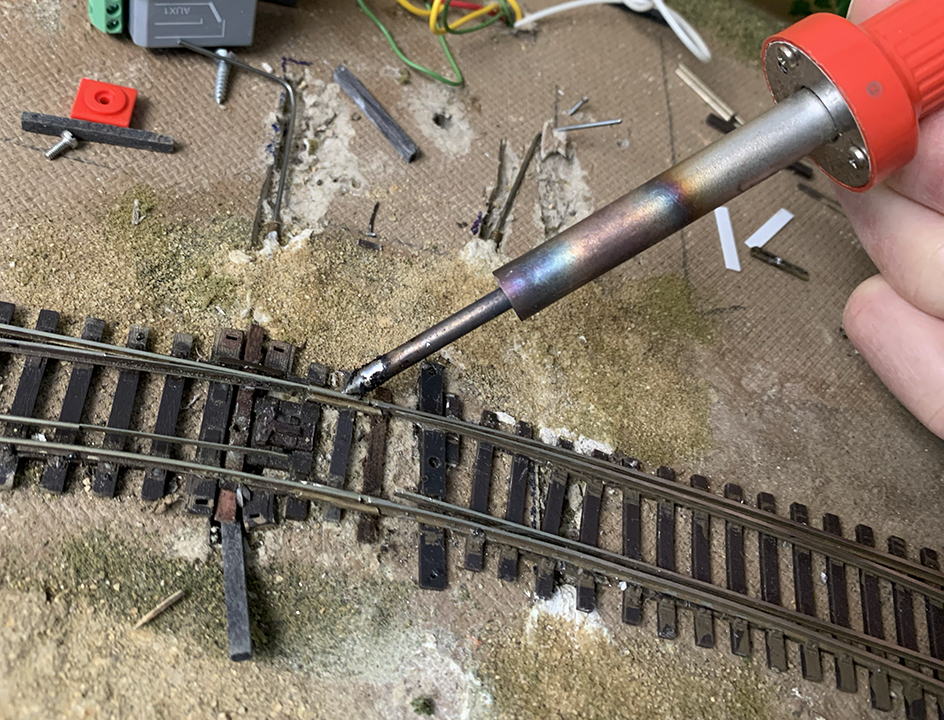
What Jim was doing in the photo above is a technique I hadn’t seen or thought of before. Rather than try and apply spikes through holes drilled in ties, Jim was making a more secure rail attachment, by drilling through the foot of the rail, and then through the tie. Note below the spike head locations. (You can click on the image to enlarge it if you wish.) This is the outer rail of the curve, looking sort of toward the aisle.

With that done, it was time to address the gauge problem. Now the inner stock rail needed to be carefully gauged and likewise spiked through the rail foot to ensure the correct gauge. Finally, I soldered the rail joints where the two curved switches came together, as this had been an area of previous problems. Of course they were carefully gauged first.
You can see above that both of the MP1 switch machines had to be unmounted temporarily to provide plenty of room to work. These will of course be re-mounted to power these two switches.
Now, as I had been doing ever since the problem was even close to being solved, I ran the severe test: one of my SP Consolidations. The long wheelbase of this locomotive type challenges the trackwork as milder tests do not.

I was so pleased to see this locomotive run smoothly through this track area. Major thanks to Jim, for coming over and lending his expertise and skills, and for seeing the need to adjust the entire track curvature in this area. Now I really hope this is the last report on work in this layout area!
Tony Thompson
Tony, it was a fun project, glad I was able to help! Now let’s see. If two pair of crossed fingers gets the job done!
ReplyDelete