But the body itself is a well-rendered insulated tank car body, of about 11,000 gallons size. That is large for most liquid cargoes of the transition era, but all right for pressurized gases such as propane or ammonia. The Athearn bottom sheet for the tank is the same one used on their riveted three-compartment tank car, and thus has to be stripped of its rivets; likewise the underframe was designed for that same three-compartment car, and has to have the triple outlets and other features removed. But these changes are quick and easy.
What then can be done with this model, beyond the ICC 105 conversions of the kind shown in the post cited in the first paragraph? Two can be mentioned. One is to shorten the tank, thus reducing its gallonage into the range of most tank cars of the transition era. I described building an ICC-104 Warren Petroleum car that way, in an earlier post (you can see it at: http://modelingthesp.blogspot.com/2011/06/tank-car-modeling.html ), and in an article in the July 2011 issue of Railroad Model Craftsman. That car received a scratchbuilt expansion dome.
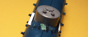
The second possibility is to forego the insulated dome, as was added to my Warren car just mentioned, and instead add an uninsulated dome. Photos show that this was not an uncommon arrangement, likely for cargoes less sensitive to temperature variation, and thus these cars were usually insulated ICC 103 cars (AAR class TMI), with lower pressure settings than most ICC 104 cars. And a very nice dome of this kind is provided in the Tichy Tank Car Detail Set, their number 3007. It happens to have the correct base radius for the Athearn insulated tank, as you can see in the photo below. Obviously that oversize Athearn valve bonnet and associated details were removed first.
The 1960s Dow lettering will be stripped off before painting The dome-top details from the Tichy set have not yet been added.
My goal here was a Mathieson Chemical tank car of 10,500-gallon size, pretty close to the Athearn tank, and in the form of an insulated ICC-103, that is, a low-pressure general-service tank car. Some Mathieson insulated cars had dome platforms, some did not, but without doubt the most common arrangement with cars like this is just a short walkway on each side of the dome. To see many examples of pre-1955 tank cars, see Edward S. Kaminski, Tank Cars, American Car & Foundry Company, 1865 to 1955, Signature Press, Berkeley and Wilton, California, 2003. Here is a Mathieson car similar to what I was aiming at (AC&F photo, courtesy Ed Kaminski). It is an insulated ICC 103, built in 1938, and is somewhat smaller than my model would be.
Close examination of the paint scheme on this car shows that the bottom sheet of the insulated jacket is black, the upper part and ends a slightly lighter color. Mathieson in those years used a medium to dark green for many of their cars, and I believe the upper part in the photo is that color.
The Mathieson car had grab irons on each side of the dome, as seen in the photo above. I added these using 0.012-inch brass wire, and also attached the Tichy dome-top details. Note that the paint has been sanded off below the dome, in preparation for attaching the dome walks.
The car I wanted to model would have been built before 1948 (when platforms and running boards were first required to be steel). Thus I needed to model the dome walkways as wood planks. Here is how I did that. With about three scale feet of scale 4 x 4-inch styrene, filed on one corner at about 45 degrees, to match the slant of the tank, I created a support for the walk. This was glued to the tank fairly high on the side, almost at the base of the dome, as suggested by the Mathieson photo above.
The prototype dome walk (see Mathieson photo) is about the length of the dome diameter, that is to say, about five scale feet. I used a scale 1 x 8-inch piece of styrene, though a thicker piece could be used. This was glued to the shorter 4 x 4 support mentioned above. In the photo below, you see one walk installed, with the 4 x 4 support piece visible on the other side.
Finally, each dome walk should have a grab iron at its edge, as is visible in the Mathieson photo above, and diagonal supports. As shown below, I made the grab irons from 0.010-inch brass wire and secured them in place below the walk with CA, then made the diagonal supports from scale 1 x 3-inch styrene strips about 8 scale inches long.
At this point I will pause in describing the model construction. Next will come a few other details, all of which comprise simple and straightforward steps. They will be followed by painting and by work on the kit underframe. I will show those steps in a following post.
I close with a small personal note, as today is December 21, the shortest day. All through my youth, I always noticed that my dad welcomed this date, because now the days would be getting longer. I wrote about that a few years ago (see: http://modelingthesp.blogspot.com/2012/12/the-shortest-day.html ), and quoted, with warm permission, a wonderful poem on the subject by Susan Cooper. Enjoy.
Tony Thompson


No comments:
Post a Comment