The topic of diaphragms on the ends of passenger cars, particularly the Southern Pacific ones I model, has been raised in this blog several times. One example, illustrating home-made striker plates, can be found here: https://modelingthesp.blogspot.com/2014/06/modeling-sp-passenger-cars-part-5.html . But perhaps more relevant is this post, about minimal diaphragms: https://modelingthesp.blogspot.com/2021/05/passenger-car-diaphragms-part-2.html .
The present post is about the cars in later years that had had the canvas or metal “folds” in the diaphragm removed, so that only the striker plate and its supports were left. These could be termed “skeleton” diaphragms. With persistence, one can find photos of this condition in published photographs, particularly in Volume 3 of the SPH&TS series Southern Pacific Passenger Cars, “Head End Equipment” (Pasadena, 2007).
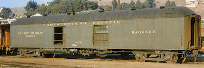
Here is a clear example, Northwestern Pacific baggage car no. 679, NWP Class 60-B; there can be no doubt that the folded part of the diaphragm (sometimes called the “curtain”) is missing at the left end of this photo, because you can see right through it! This was taken at Tiburon about 1945 (Steve Peery collection).
Here is color view of another NWP baggage car with a diaphragm in the same condition (Bruce Heard photo). Notice, incidentally, how faded is the Dark Olive Green! Photo at Tiburon about 1958. If you click on the image to enlarge it, you can easily see the state of the diaphragm at the right end of the photo.
Possibly diaphragms were reduced in this way for cars that would not often require passage from car to car, and those passing would be crew, not passengers.
Some Precision Scale HO baggage cars have been modeled this way, as I’ve mentioned previously. Shown below are two angles on one of these models with this type of diaphragm.
The only points I would raise with respect to this model diaphragm is, first, that there is visibly some floor element in prototype diaphragms like this, despite their lack of side curtains. There is no diaphragm floor in the model. Second, some prototype photos seem to show two attachments at the top corners of such a diaphragm, not a single center attachment as you see here. Admittedly that may have varied from car to car.
I decided to see what I could do to model this appearance. I decided to use styrene to model both the floor and top attachments, and use a Coach Yard stainless steel striker plate. This was for a car with couplers extended a ways outward, so I wanted a sizeable diaphragm length. The styrene I used was scale 6 x 10-inch (the floor element) and 6 x 6-inch size, attached with canopy glue. Here’s a photo of the front and back of what I built.
These versions of the skeleton diaphragm are fairly tall, a little too tall for older models like the Ken Kidder brass head-end cars (a product of the height of the striker plates). But they work all right for other models, such as my Soho postal-baggage car, Class 70-BP-15-3, presented as SP 5150. Shown below is this car with a skeleton diaphragm like those shown above.
I will explore further variations in this type of skeleton diaphragm, using other striker plates, and also exploring less length of the projecting diaphragm structure, for cars with differently located couplers. As they are applied to models, I will show them in future posts.
Tony Thompson


No comments:
Post a Comment