As in the recent posts in this series, I continue in this post to address lightweight passenger cars of the Southern Pacific. (Finding earlier posts in the series is easily accomplished by using “modeling SP passenger” as the search term in the search box at right.) In the immediately preceding post, no. 19, I was discussing trucks for these cars (see that post at: https://modelingthesp.blogspot.com/2024/06/modeling-sp-passenger-cars-part-19.html ).
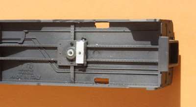
I mentioned in that previous post that I’d like to use some of the Central Valley no. 139 trucks that I have (trucks rebuilt with Northwest Short Line wheelsets). These trucks have their bolster hole in the truck center, as do most trucks. But the Rivarossi trucks that come with the lightweight cars most definitely do not have centered attachment and holes. The photo below shows that hole well to the right of center.
I have shown in an earlier post (no. 10 in this series) that this truck design, with the sprung “coupler arm” culminating in a horn-hook coupler, can be modified to accept a Kadee coupler in its own box (see it at: https://modelingthesp.blogspot.com/2021/04/modeling-sp-passsenger-cars-part-10.html ). If that is done, of course, the truck remains in use and its off-center attachment is not a problem.
But the Central Valley no. 139 trucks do have a center bolster hole. Thus the Rivarossi truck attachment location, shown in white below, is off center in the car body truck space (by about 1.5 scale feet) and has to be replaced. In addition, the molded “alignment pins” as I call them, have to be removed. These are quite evident on either side of the bolster in the image below.
So a bolster pad has to be created that is centered in the car body truck space. I experimented with various sizes of styrene strip, and found that the height of the cylindrical center of the bolster, shown above, is about 8 scale inches. I built up a bolster pad of that thickness, attached using styrene cement, as shown below. This was done because attaching the Central Valley trucks to the off-center bolster had already shown that coupler height was going to be correct.
Next I had to address coupler placement. The two lengthwise members (sills?) molded on the Rivarossi underbody are lined with rivets (as is visible above), which I removed near the car end, and then glued on a pad of 0.030-inch thickness styrene. I then mounted Kadee couplers in their own boxes.
The completion of these modifications allowed the view above (the car is a 10-6). Note that the trucks are now centered where they should be, and coupler knuckles are located just outside the outer edge of where the diaphragm face plate will be. This means that cars can be nearly in contact during operation.
My last task on this car is to add the diaphragm face plate and stabilizer bars to the Rivarossi “surround” on the end door. (See my previous post about doing this: https://modelingthesp.blogspot.com/2023/09/modeling-sp-passenger-cars-part-17.html ). When it’s all done, the diaphragm area will look like this (another 10-6):
I am pleased with my success in adding some of the Central Valley trucks to these cars, both because they add weight and because they separate the coupler from the truck, something occasionally troublesome with retaining the Rivarossi “Talgo” coupler arrangement.
Tony Thompson


No comments:
Post a Comment