Reference pages

Tuesday, August 29, 2023

Standards for commercial freight cars

 I have posted a number of times on the topic for today (if you’re interested, you can readily find those earlier posts by using “standards” as the search term in the search box at right). Usually I mean standards for some particular aspect of modeling, such as trackwork, scenery, weathering of rolling stock, etc. But today, I mean the standard to which we hold commercial models.

The recent Rapido Trains HO scale models of Southern Pacific Class B-50-15 and -16 box cars brought this topic back to my attention. One person, whom I won’t identify, referred to these models as a “flop.” It’s true, the boards on the single-sheathed cars are somewhat too wide, and the Class B-50-16 cars have the bolster (and side post above it) mis-located by 6 scale inches. Does that make the entire production run a “flop?”

Well, of course almost all of us want more accurate models (I’ll comment on what that word really means in a moment). Some readers may remember when Model Die Casting produced a “modern” flat-roof box car, combining elements of at least three different actual box cars. Doubtless this was done so the model would be “generic,” and they could put lots of different paint and lettering schemes on the car; but the model wasn’t accurate for any prototype car.

Now exactly what is an “accurate” model? Does it consist of more than the right length and height and shape of the represented freight car? You might say we can start there. Then, at one extreme, as I showed some time ago for a separate topic (the post is here: https://modelingthesp.blogspot.com/2020/07/waybills-part-72-is-it-merely-visual.html ), you might settle for this:

Of course most of us want more than this, though this item does operate well. And hey, in an operating session, you just move the cars where they’re supposed to go, right? no reason to examine them.

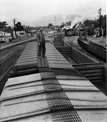
We make lots of compromises already. I can start with the roof of house cars. Our modeling of metal-grid running boards really falls terribly short, despite some lovely products in etched metal (Plano Products and others) and even in styrene (Kadee). But look at this photo (Richard Steinheimer, at San Luis Obispo in 1953; DeGolyer Library, used with permission). I am certain that no one’s model running board looks like this.

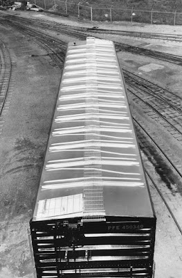
Or let’s look at an entire roof, in this case PFE 450340, Class R-70-13, photographed by Pacific Car & Foundry at their Renton plan). As in the photo above, the ratio of, shall we say, air to iron in this running board is immensely different from the model versions.

So does this mean that every model out there with a representation of a steel-grid running board is a “flop?” No? Why not, if a discrepancy of 6 scale inches makes the Rapido Class B-50-16 a flop?

Of course we can go on to list many, many other compromises in model freight cars. Ladders and grab irons are typically over-thick in commercial models; side doors are often too thick; sill steps are often the wrong shape and size; end corrugations often not really the right shape; and don’t get me started on underbodies and brake gear. Those all gotta be flops, too, right?

Of course, I’m exaggerating to make a point. Every manufacturer tries to do a good job (well, most of them do), and inevitably there are going to be compromises. Hopefully as the years go by, standards increase and we get better and better models (for my modeling era, my freight car examples nowadays, in addition to Kadee, would be Tangent Models and Rapido, and one could add more, especially in locomotives).

Back when I wrote reviews of freight cars and freight car kits for Railroad Model Craftsman, then edited by Bill Schaumburg, he repeatedly reminded me never to say something was “wrong” in a model, but either indicate how it could be fixed, or explain that it was a minor discrepancy. His point? Many less-expert modelers, seeing the word “wrong,” immediately decide not to buy one, and more seriously, tell everyone they know that the model is “wrong” (after all, RMC said so) and no one should buy one.

In directing me this way, Bill was no doubt protecting the tender feelings of manufacturers, to some degree, but he was also making a very important point: keep a sense of perspective. Don’t be one of those people (most of us can name one or two) to whom no error is too small to be blown up into, shall we say, a “federal case.”

Tony Thompson

Saturday, August 26, 2023

Modeling SP passenger cars, Part 16: head-end

In previous posts in this series, I have addressed a wide variety of Southern Pacific passenger cars, many of them head-end cars. (Previous posts are easily found by using “modeling SP passenger” as the search term in the search box at right.) 

In the present post, I return to head-end cars. Although some SP passenger cars may appear generic, in fact the great majority had individual characteristics, especially the Harriman-era heavyweight cars. This post is about such cars. 

Probably the best and most complete options for modeling several of the Harriman heavyweight head-end cars are the kits from Southern Car & Foundry, or SC&F. (I briefly described these in an earlier post, which is at: http://modelingthesp.blogspot.com/2012/10/modeling-sp-passenger-cars-head-end-cars.html ). 

I had Dennis Williams build two of these kits for me, except for window glazing, and paint them the standard SP color, Dark Olive Green. In my post about that work, I mentioned my two choices of commercial paint that are quite accurate for this color, from Star Brand and Tru-Color (here is a link to that post: https://modelingthesp.blogspot.com/2014/07/modeling-sp-head-end-cars-part-6.html ).

One of these SC&F kits represents a 60-foot Harriman baggage car, the underframe of which was shown being considerably stiffened in the earlier post, linked in the preceding paragraph. I lettered the car with the excellent Thin Film decals, set HO-160, lightly weathered it, and installed the window glazing and diaphragms. With those additions, the car was complete, and could be joined to its underbody.

The second car is another SC&F kit for a head-end car, this one a 70-foot baggage car, distinctive with a pair of windows on each side. The SP owned quite a few of these, so they are really an essential part of an SP mail train. But there is one small defect in the SC&F kit: it is for the slightly different Union Pacific version of this Common Standard car. The difference? The windows are wider. 
 
Having kitbashed one of these cars with a lot of work from a couple of Athearn baggage cars (you can see my magazine article about it at: http://modelingthesp.blogspot.com/2014/06/my-baggage-car-article-in-prototype.html ), I saw the different window proportions right away. The UP window is 2 feet, 8 inches wide, while all the SP windows were 2 feet, 5 inches. Now many would not notice, but having worked directly with these windows, I can’t miss it. Ah well, it’s a lovely kit, and few visitors would notice, anyway, so I’ll go ahead and use it. 
 
I wanted to show the nice design arrangement in these kits for installing windows (created by SC&F principal Jon Cagle). In the one-piece body, on the interior, are pockets into which the glazing parts drop in perfectly. Here’s an interior view into an as-received 70-foot body casting, showing one such receptacle for the end window.
 
Then the SC&F kits give you a very nice way to paint the windows: the acrylic “glass” has a peel-off paper cover, that has been laser-cut so you can peel off the part covering the window frame, while leaving the paper over the window glass. These window parts are shown below (four end windows, four baggage-door windows), next to the inside of one of the baggage doors, again with a pocket into which the glazing drops.

Ordinarily, the modeler would simply peel the frame covering, install each window, paint as part of the overall body, and lastly remove the paper over the glass. Since my car body was already built and painted, I had to pre-paint each of these end windows, then install them in the car body, then decal letter. This car, like the 60-foot car, had the body not yet attached to the underframe. 

In addition to the window installation, I also needed to stiffen the underbody of this car, not as extreme a problem as it was with the 60-foot car (that issue was described here, repeating the link: https://modelingthesp.blogspot.com/2014/07/modeling-sp-head-end-cars-part-6.html ). 
 
Once again, I used K&S Engineering brass rectangular tubing, stock no. 266, which is 5/32 x 5/16 in size, as a stiffener. This is supplied 12 inches long. I cut an 8-inch and a 4-inch piece. These were glued with canopy glue and clamped. Below you see the long stiffener being glued. The original weights, stacks of pennies, are visible.

With the stiffening completed, and windows inserted, I had the car nearly complete, only needing addition of diaphragms. I used modified American Limited diaphragms, using only the inner part of the commercial product (you might wish, for example, to see this post: https://modelingthesp.blogspot.com/2021/07/passenger-car-diaphragms-part-4.html ).
 

This completes work on my two SC&F head-end cars, both beautiful models and with correct Harriman underframes, nice to have. They will surely be included in the extra mail train that runs as part of most of my operating sessions.
 
Tony Thompson

Wednesday, August 23, 2023

Route cards, Part 22: additional examples

This post extends the coverage I have been posting about these interesting railroad documents, small cards usually applied to the route card boards on a freight car, nominally 5 x 9 inches in size. There were in fact a range of informative cards that might be attached to those boards, but in the present post, I am concentrating on the ones that would direct the movement of a car, to a particular yard track, or outbound train, or specific destination, including interchange.

As before, all these were loaned to me by Michael Litant, to whom I am indebted for this generosity. If you’re interested in previous posts in the series, I recommend using “route cards” as the search term in the search box at right.

I’ll begin with a clearly identified card, in use at the Oakland interchange of the Western Pacific and Southern Pacific (it’s an SP card, 3 x 4 inches). The car in question is clearly PFE 8475, a 40-foot plug-door reefer, Class R-40-26, which is empty and is en route to Salinas, on July 29, 1965.

You might wonder about the bold number “82” on this card. As it happens, I do have a copy of SP’s Oakland route card meanings, which I showed in an earlier post (you can find it at: https://modelingthesp.blogspot.com/2016/05/route-cards-10-southern-pacific.html ). The code “82” means destined to Coast Division beyond San Jose, which exactly describes Salinas.

Next up is a classic interchange card, this one from the L&N, for transfer to the Monon. It’s 3 x 3 inches. Only the car number, 164194, is given, so it's not clear who was the owner; and the location is only a station number, 31, which I can’t identify on the L&N. (The “31” might also be the date.)

Another example of what is likely an interchange car is this one from the Kentucky & Indiana Terminal Railroad Company at Louisville, Kentucky. The K&ITRR was the owner and operator of a bridge over the Ohio River between Louisville and Indiana, and switched a number of industries near their yard in Louisville. For many years, the K&ITRR was jointly owned by the B&O, the Southern and the Monon. This one is 3 x 4 inches, and the car was IC 120891 (a 40-foot box car); the cargo, whiskey (not unusual in Kentucky).

Found under the above K&ITRR card was a different card, this one from the L&N, and naturally for the same car, IC 120891. Its date shows only “25” while the K&ITRR card above only shows “12” for a date, possibly 15 days later but possibly much later, with a different cargo. I don’t know what “Dispatch” may mean, possibly an urgent move. The card is 3 x 4 inches.

Although the great majority of the route cards I have seen are rectangular and meant to be written in a dimension parallel to their long side, there are exceptions, such as this Grand Trunk Western card, 3 x 3 inches, and evidently intended to be attached in a diamond orientation, which is how I’m showing it. It is another interchange card, in this case to the Detroit & Toledo Shore Line (D&TSL). Note, though, that the destination stamp is arranged as if the card were to be conventionally oriented.

One final example has a very complete set of information, almost of waybill completeness. It is from the Kansas City Terminal Railway Company and is dated April 18, 1967. It is 4 x 4 inches and has been typed. The car was 50-foot mechanical refrigerator RMDX 717 (an ART mark) and the cargo, frozen turkeys from Norbest Turkey, en route to New York City, care of a Produce Distribution Agency, outbound via N&W.

These examples were chosen either for intrinsic interest or because they extend the range of types of route cards that I have seen. I certainly find them all interesting and informative.

Tony Thompson

Sunday, August 20, 2023

The Rapido SP box cars: brake gear

When the Rapido Trains HO scale models of Southern Pacific box car classes B-50-15 and -16 were first released, I posted a description of the prototype class histories and some details about the models (that post can be found at this link: https://modelingthesp.blogspot.com/2023/07/the-new-rapido-sp-box-cars.html ). In the present post, I address the brake gear on the models. 

[I have also posted a description of the background to six of the paint schemes offered by Rapido (the seventh is too late for my modeling era). See the post here: https://modelingthesp.blogspot.com/2023/08/the-rapido-sp-box-cars-models.html .]

When these two car classes were built in 1925 and 1927, the standard freight braking system was what is known as the K brake, with air reservoir, cylinder and valve all in one component. Some of the Rapido models were manufactured with this brake, as I show below.

Starting in 1933, new freight cars were required to be equipped with a new air brake system, the AB brake, in which reservoir, cylinder and valve are three separate parts. It was further required that at any “major” shopping or repair, that existing K brakes were to be replaced with AB brakes. For that reason, by the end of World War II, cars with K brakes were becoming unusual. They were finally banned in interchange in 1953.

The AB brakes performed much better with longer trains, with both quicker application and quicker release than K brakes. They also had two reservoirs instead of one (though the two were combined into one component in the AB brakes), better for emergency applications. So replacement of K brakes with AB was not some bureaucratic detail but a significant technical improvement.

Rapido made some choices as to which of their paint scheme cars would have K vs. AB brakes which are hard to understand. For example, post-1946 car lettering was applied to a Class B-50-15 body with K brakes. But in all such cases, a small envelope was in the box, containing AB brake parts for the modeler to install. As I model 1953, I don’t wish to operate any of the cars with K brakes, except for the SPMW car. On-line cars such as MW cars could still operate with K brakes, they just couldn’t be interchanged.

The change to Rapido AB brakes is pretty simple. I sliced off the K brake component from below (its peg was inserted into the car floor) and discarded it. Important point: before removing the K part, snip the linkage to the lever right at the crossbearer (tip of the cylinder). See below. This retains the “chain” part of the linkage already on the car.

Then as stated above, slice below the K part and remove. You should then have a clean floor (except for the scar where the K gear was).

The AB parts provided have an insertion peg or two for ease in factory model assembly. One can either drill holes for these pegs, or slice them off and simply glue the parts flush to the floor. With a strong and tenacious glue like canopy glue, the latter approach is quite practical, and easier. But first, let’s see where each piece goes.

In the photo nearest above, you can see at the leftmost of the two cross-bearers that there is a lever, which in turn is connected to another lever behind the other cross-bearer to the right. These two levers are correctly located for the AB brake, so they remain where they are. The new AB cylinder will be located to connect with the left-hand lever (above).

Below is a photo of a Rapido box car underbody with AB brakes as manufactured.  This is the arrangement to be reproduced using the AB brake parts supplied with K-brake models. 

The value of the view above is that it clearly shows which piece of piping is which, looking at the envelope of AB parts in the model’s box. Here are those parts, arranged roughly as above. All three components, reservoir, cylinder and valve, have nice receptacle holes for the piping. (The piping is wire.)

I decided to first glue the cylinder and its pipe onto the car floor, then, using canopy glue, fit the other two pipes into the intended holes in the reservoir, and then arrange onto the car underbody. The last step is to fit the three pipes into the valve, which is touchy, but possible. I confess that in one case I just omitted the pipes altogether. In a side view, they are invisible anyway. But the AB brake components are visible from the side, so they are the minimum to install.

The cars with the newly-installed AB brakes are headed for the weathering bench, from which they will go into layout service. I like these cars and congratulate Rapido for choosing them to manufacture.

Tony Thompson

Thursday, August 17, 2023

Figures, Part 10

 By figures, of course, I mean HO scale people, not columns of numbers. I’ve obviously written nine previous posts about this general topic; probably the easiest way to find them is to use “Figures” in the search box at right. For today’s post, my Part 2 (at: https://modelingthesp.blogspot.com/2017/05/figures-part-2-modifications.html ), would be the most relevant one. It’s about adding an invisible (or very low visibility) base to figures.

Do you have a few figures like the ones below? The two track workers are from a Merten set, no. 870, but I don’t remember the source of the center figure, with the transparent but very thick base. I really don’t want figures like this on the layout; so few people in the real world stand on little discs. And obviously the center figure is very poorly rendered, but can serve on the layout if well away from the aisle.

The first step is to remove these bases. I use a small side cutter, and simply clip next to the feet around the entire figure. Here’s a first cut:

The disadvantage of these gray bases is that they are part of the figure, so clipping away the base leaves that additional thickness at the bottom of the feet. At one time, I extremely carefully removed that added thickness. But in fact, if painted black to match the shoes, it becomes invisible on a base, so I no longer worry about that thickness. You can see it below, unpainted.

For the figure with the transparent base shown above, the base is a separate part, glued to the feet, and usually can be sliced off easily.

I use clear styrene sheet from Evergreen, of 0.010-inch thickness, for bases for figures like these. I just cut a square or rectangle big enough to accommodate each figure’s width and stance. Exact dimensions not at all critical, as long as the base is big enough.

Next comes attaching the bases. I use a dab of canopy glue on each foot, then stand up the figure on its clear base with a steel block for support. Then let dry for a hour or so. In the photo below, you can see the white of the recently applied glue. The glue will dry clear, and is surprisingly strong.

The figures shown above were only part of a larger project to ready additional figures for use on the layout. Below I show several of them together, with a photo angle intended to make the clear base visible, though of course in use the opposite visibility is intended. (The man holding the box at right is from the excellent series of figures from June’s Small World, of Edmonds, WA.)

Another couple of points to recognize: first, clothing for men is fairly ageless, but for women, visible aspects such as skirt length need to fit your era. Second, plenty of figures that may be included in an otherwise-useful set that don’t seem to have any use on your layout. Sometimes you can make changes. Both are touched on in discussing the photo below.  

Notice how different the skirt lengths are on the two women. They do look like women of quite different ages, so the different lengths may be okay; but the shorter skirt, about knee length, was probably not very common in 1953. I will place her farther back in the layout. 

Second, the two men apparently are holding shovels (of quite different and perhaps odd shapes). I don’t have extensive need for gentlemen shovel-wielders, but both can be re-purposed by painting the apparent shovels as brooms. I used Tamiya “Desert Yellow” (XF-59) for this. And both of these somewhat clunky figures will be farther from the aisle.

These procedures can be used for a wide variety of figures, and most importantly for me, has successfully minimized the size and visibility of bases for figures. I don’t like to glue them in place on the layout, but instead can and do move figures around from time to time, so scenes don’t remain static.

Tony Thompson

Monday, August 14, 2023

Route cards, Part 21: more examples

In a previous post, part 18 in this series, I showed examples of route cards from Michael Litant’s collection of late-1960’s cards. These are cards affixed to small route card boards on freight cars, to direct switch crews where the car is going. You can read that post at: https://modelingthesp.blogspot.com/2023/07/route-cards-part-18-further-examples.html . To repeat, these are route cards, not the grading cards I showed in the previous two posts in this series.

I will begin with a Northern Pacific classic route card, printed for Duluth Yard, and likely Track 9. The card is interestingly stamped “Superwood,” presumably a shipper, though it could be a destination for pulpwood or lumber. It’s just 3 x 3 inches in size. This very bold number is something that could be achievable in HO scale.

Next in this series is a classic “empty return” card from the Long Island Rail Road, very plainly marked PRR for, of course, the Pennsylvania. It too is 3 x 3 inches. Very likely the PRR was the road from which the car had originally been received. Such a return was very typical practice.

Here is an example of a more complete description of an empty car, this one from the Burlington. The car is to be returned to the Belt Railway of Chicago. The car which received this card was GN 15423, a 40-ft. steel box car, and the date on the card is Nov. 15, 1957. This card is 4 x 5.5 inches in size.

The next one I will show is at the other extreme from the foregoing card; it simply identifies the car destination and contains no other information, not even the name of the issuing railroad. I confess I have no idea what or where “Irving Dock” is, but perhaps a reader may know. But there is no confusion about what is intended. It is 3 x 3.5 inches in size.

Another good example is this one, identifying “West 53” at Ogden, Utah. The car is evidently CB&Q 41420, a 40-ft. steel box car. My guess is that this is a Union Pacific card, but it could be from the D&RGW. Green in color, the card is 4 x 3 inches.

To me, each of these examples is interesting in its own way, illustrating ways the prototype directed car movements at, shall we say, the track level. I have used small blank squares of paper in the past for such route cards on HO scale models, but intend to explore whether bold letters like a couple of the above cards might be practical.

Tony Thompson

Saturday, August 12, 2023

The Rapido SP box cars: the paint schemes

When the Rapido HO scale models of SP box car classes B-50-15 and -16 were first released, I posted a description of the prototype and some details about the models. (That post is here: https://modelingthesp.blogspot.com/2023/07/the-new-rapido-sp-box-cars.html ). In the present post, I want to show several of the models as offered.

Class B-50-15 was built in 1925-26 and Class B-50-16 in 1927-28. At that time, SP lettering called for the SP initials to have periods, e.g. S.P., as did many railroads. But in 1931, SP decided to discontinue the use of periods in the reporting marks. Thus the earliest paint scheme offered by Rapido is correctly called “1931–1946,” accurately describing the span of time involved. Below I show one of the models in this paint scheme. Some cars, of course, didn’t get this lettering replaced for years after 1946.

In 1946, SP made considerable changes in its lettering for locomotives, passenger cars, and freight cars (the latter changes are described in considerable detail in the book, Southern Pacific Freight Car Painting and Lettering Guide [SPH&TS, 2016], by Dick Harley and me). For SP freight cars, the road name was now spelled out, instead of mere initials, for the reporting mark. 

Below is one of the Class B-50-15 model cars that had been steel-sheathed, in the 1946–52 scheme. (In 1952, SP discontinued the use of the 1-inch stripes above the road name and below the car number, which is why Rapido uses that year in its paint scheme description.) One might, in passing, wonder why a car with a post-1946 paint scheme carries a 1936 reweigh date — but I digress. It’s fixable.

Rapido also offers what they call a “post-1955” paint scheme, with spelled-out road name but no stripes, which is narrowly correct, but by 1955, and thereafter, SP returned to use of the initials “SP” only as the reporting mark. I didn’t get one of those cars.

The steel-sheathing program for both these box car classes originally seems to have begun in the mid-1930s, when SP instituted  an overnight package (LCL) service between Los Angeles and San Francisco, integrating long-distance rail with their trucking service, Pacific Motor Transport, for local delivery. This was soon named “Overnight” service, and a distinctive paint scheme developed, using all-black cars with Light Orange lettering and striping (the orange was a PFE color dating from 1929, and two years after its adoption for the Overnight cars, would become famous as “Daylight Orange”). 

That scheme would vanish at the beginning of World War II, when special freight services like the Overnight trains were discontinued for the duration. So this scheme was long gone from 1942 onward, but I had to have one for my display case. Note that these cars had been renumbered into a 9000 series, but recovered their original numbers when returned to ordinary freight service.

When the war ended, SP like most railroads was quick to reinstate special freight service, including the Overnight trains, but with a dramatic new paint scheme. Car bodies were still black, but an SP medallion in yellow was added, along with a red ball and a gold arrow through it. SP bought 450 new box cars for the core of this service, but repainted many of the Class B-50-15 and -16 cars into this scheme also, to fill out the fleet. This is a signature SP freight car scheme.

As it happened, the pre-war Overnight cars did not all return to freight service at the beginning of the war. Instead, SP repainted 99 of the cars to join others of these two boxcar classes in head-end passenger service (AAR type BX cars, with signal lines, Type E couplers, and steel wheels). They were painted in Dark Olive Green with gold lettering (later Dulux Gold), and could be seen this way for some years after the war. But those BX cars were all returned to freight service during 1948-49, so it’s display case for this one.

This particular model, numbered 9008, represents a Class B-50-15 car, SP 15344, converted to passenger service in 1936 though still wood-sheathed, and still bearing the original lettering these cars had at the outset of Overnight service. This particular car returned to freight service under its original number in 1943. (This information is from the the SP Car Ledgers, now at CSRM.)

Lastly, Rapido did decorate a few models in a Maintenance of Way scheme, as SP did with large numbers of these cars in the 1950s and later. This particular car, SPMW 1399, originally SP 14772, was not converted to MW service until 1955, but I will accept that modest time-warp.

I did admire the ability of the manufacturer, on these MW cars, to add the ubiquitous SP “danger” signs in English and Spanish, entirely readable.

All these models are shown above in the state I received them. Aside from the pre-war Overnight car destined for the display case, all will receive suitable weathering and, where needed, reweigh and repack stencils. More on that at a later date.

Tony Thompson

Wednesday, August 9, 2023

Route cards, Part 20: more grading cards

I recently posted a selection of the “route cards” used to indicate grading of freight cars for loading, using a number of cards loaned to me by Michael Litant. I also explained the usual grading from A, B and C down to D or E or X, depending on the individual railroad. You can read that post here: https://modelingthesp.blogspot.com/2023/07/route-cards-part-19-grading-freight-cars.html .

These cards were usually the size of typical route cards, around 4 x 6 inches, but not always. Moreover, some prototype photos suggest that grading cards were fastened to placard boards on house cars, not to the route card boards. That is consistent with some of the variations among cards in Michael’s collection.

I’ll begin with an interesting example, showing four possible grades, and intended to be folded to show only the selected grade, like some of those shown in the previous post. It is from the Nickel Plate. Like many of these cards, it does list typical cargoes of each grade as an aid to inspectors. The unfolded card is 4 x 6.5 inches, and you see both sides below.

The selected grade was B, and that part of the folded card was outermost; it was graded at Tipton, Indiana on August 3, 1965, for B&O 467708, a 40-foot steel box car. You may also note that Grade X has sections for both house and open-top cars, similar to the New York Central card in the previous post.

Another interesting example is this C&O card. It is 4 x 8 inches, and does not appear intended to be folded. The intent is that the card section that is signed by the inspector, is the chosen grade (in this case, grade B). The other side is an example of the multi-use card, that can direct yard crews to take a particular action, in this case either to clean out or to wash out the car. I can’t read the car number or location of grading, but it was an Illinois Central car.

A somewhat different design was used by the Grand Trunk Western, as shown by the 3 x 7 -inch example below, again, intended to be folded. It doesn’t show letter grades, just three categories: Grain, Food; Cement, Salt, Merchandise; and Rough Freight. It is stamped from Durand, Michigan.

My next example again is different than the typical grading card. It’s from the B&O and is 4 x 8 inches in size. It is not apparently intended to be folded, but like the preceding cards, provides for the inspector’s signature and car identification to be placed in the card segment for the selected grade. Interesting, these are not alphabetical grades but numerical ones, and contain detailed lists of commodities for each grade. Note that Grade 5 is not a loading grade, but is an instruction to clean the car. And Grade H is to be used for cars needing to be sent homeward, either for repairs, for interior maintenance, or because it’s an assigned car.

Finally, one more example of a card intended to be folded, just 3.5 x 5.5 inches in size, issued by the Western Pacific (and used also on its subsidiaries, Sacramento Northern and Tidewater Southern). It has the usual four letter grades and definitions, This car, D&H 18643, a 40-foot steel box car, was inspected at Stockton, California on August 27, 1967 by Trujllo, and given a B grade for canned goods.

These are all interesting example of individual railroad systems of grading, and clearly show that there was no real standard, though the content of each level of the categories is quite similar from railroad to railroad. As I mentioned in the previous post, there are some modeling possibilities here, and I will discuss those in a future post.

Tony Thompson

Sunday, August 6, 2023

The new Tangent SP box cars

Tangent Scale Models has just released a run of distinctive Southern Pacific box cars, the cars with 7-foot side doors built from 1950 through 1953, about 9,500 cars (Tangent somehow came up with 19,000 cars). These were SP box car classes B-50-28 through B-50-33, except for the 50-ft. cars of Class B-50-30. In the postwar era, they were distinctive with a 10-foot interior height, when most railroads were shifting to a 10-ft., 6-inch interior height; and all had 7-foot side doors and diagonal panel roofs.

(A detailed history, and detailed listings of all car specialties, can be found in my book, Box Cars, Volume 4 in the series, Southern Pacific Freight Cars; revised edition, Signature Press, 2014).

Below are some builder photos of Class B-50-28 (Pullman-Standard photos for SP, Stanford University Libraries, used with permission). I’ll begin with a side view of SP 102199. That wider side door stands out, compared to older cars with the then-standard six-foot door.

The cars had Improved Dreadnaught ends,with two distinctive features. Because of the lesser interior height, the end ribs were of 3/4 pattern (3 ribs in the upper section, 4 in the lower), and the top-most rib was not symmetrical in shape, but had a flattened bottom side. And a narrow, shorter rectangular rib was located across the top of the end. You can see those features below in the prototype photo for SP 102199, including the Miner hand brake.
These cars, like most house cars built after 1948, had diagonal panel roofs. I show below the roof of SP 102199, and will compare below this roof to the model roof. Note also the Apex running board.

The new Tangent model is beautifully done, and reproduces all of the prototype features mentioned above. I was really pleased after examining it. Below is an overall view of my model. The roof is perhaps a little heavily rendered (the photo above shows that the prototype rib heights are smaller).

The ends capture exactly the appearance of the prototype end shown above, including that flattened rib at the top of the end, something rarely modeled by manufacturers. And this model has a Miner hand brake.

And I should also mention a very nicely rendered underframe, with the features of the prototype as SP purchased them.

All in all, a beautiful job of capturing a distinctive prototype. The models, including cars lettered for T&NO and for the Cotton Belt, are available now (see them at: https://www.tangentscalemodels.com/pullman-standard-southern-pacific-lines-postwar-406-box-car/ ), including a kit with all the variations in doors, hand brakes and running boards of the various SP prototypes. I’m impressed, and I think many other modelers will be too. Check them out!

Tony Thompson

Thursday, August 3, 2023

Electrical wars, Part 20: one more time

Sigh. You can tell from the series number of this post that I do have electrical issues from time to time on my layout. (Previous ones, if of interest, are most easily found by using “Electrical wars” as the search term in the search box at right.) I’ve called this installment “one more time” because it addresses a particular switch that I’ve replaced once and then rebuilt after that.

This is probably the most-used switch anywhere in my trackwork, or at least roughly tied for first. It’s both the switch off the Southern Pacific Coast Division main line, onto my modeled Santa Rosalia Branch, and is also the lead into the yard trackage for my town of Shumala. It is used many, many times in every operating session that includes Shumala.

Below is a photo of the switch in question. At left is my trusty multi-meter. I’ve written this comment many times, but will repeat once more: I have absolutely no idea how anyone can build and operate a layout without one of these in frequent use (but I do know of examples). The edge of the turntable pit is visible at top.

I have, in recent op sessions, begun to have one of the point rails in this switch (the one nearest the camera) become dead — intermittently, the worst kind. Partway through my most recent session, it stopped being intermittent and became continuously dead. This one I could diagnose provisionally, because the switch had been rebuilt for DCC and has a jumper wire from each stock rail to each point rail. Earlier, when I had the intermittent “dead-ness,” I re-soldered that jumper. Or thought I did. 

Very careful visual examination, and meter use, showed that it was now disconnected. Possibly the solder joint had not actually been re-soldered that previous time, but only pressed into contact, which would account for the intermittent dead behavior. I now very carefully cleaned the wire and rail, and re-soldered, being sure to check for mechanical connection. So that was fixed.

But there was still a problem. The Frog Juicer with which this switch is equipped did not consistently trip. This was complicated to trace, but eventually I concluded that it apparently was due to the styrene block in the gap at the front of the frog, sticking up and lifting locomotive wheels over the gap, thus not allowing said wheels to contact both sides of the gap at once. 

When a locomotive wheel does touch both rails at such a gap, and the rails are of opposite polarity, there is a short. The Juicer is triggered by that brief short, and reverses the frog polarity and removing the short, but if there is no short, the Juicer doesn’t trip. That offending gap is visible above — if you know where to look. Here’s the same photo with a helping arrow:

Carefully cutting the height of this styrene block down sort of damaged it, so I pulled it out entirely. I don’t know why it had gotten raised up, perhaps displaced by a derailment at some point, but no matter. I replaced it with a fresh little piece of styrene. Now it all works fine.

Let me hasten to say that this theory of the gap behavior, and the failure of the Frog Juicer to trip, is still just a theory. It seems to fit my problem, and is consistent with what appears to be the solution of the problem, but is nevertheless just a theory. I would appreciate comments from anyone who knows more about this technology that I do (likely most of you readers). 

Is there a moral to this story? Probably not, if you’re an “electrical ace” and rarely have such problems. But the gap-filling styrene problem and the Frog Juicer behavior is kinda subtle, and if all else fails in your next electrical misbehavior, it could be worth a look to see if you might have this kind of thing, too.

Tony Thompson