Reference pages

Thursday, May 30, 2024

Wheel faces and wheel treads

Here I am referring to the faces and treads of wheels on model railroad cars. These are not terribly prominent features on either prototype or model cars, but they should still look “right” on a layout or even in a display case. For background on how trucks are constructed and a little about modeling them, you may wish to look at my article in Model Railroad Hobbyist, September 2016. (This issue is still available for free, to read on-line or download, at www.mrhmag.com .)

I will begin with an informative overview of what a truck looks like. It happens to be a Bettendorf T-section truck, the later version with the little rib above the journal box connecting onto the frame, very visible in this view. The wheelsets (wheel-axle assemblies) are faded out in this view so the bolster and side frames can be seen better. (Bettendorf graphic, Car Builders Cyclopedia, 1919)

The parts of the wheelsets that we can see in models are primarily the outer wheel faces and the treads. The inner faces and axles are not very visible on most model cars. Since I model during the transition era, when roller bearings were still fairly uncommon, the solid-bearing truck technology was predominant. The journal boxes you see above would be opened to add lubricating oil to the journal box, and inevitably this leaked out of the back of the box onto the wheels.

The result was an accumulation of oil on wheel faces, which of course attracted and held dust and dirt from the right-of-way. Before long a rather thick layer of oily “crud” characterized every wheel face. The photo below (taken at the Portola museum by Richard Hendrickson) illustrates what I mean. Note, incidentally, that the cast steel bolster is hollow and you can see clear through it. You may click on the image to see the wheels more clearly.

Of course, new model trucks, and the trucks on “ready-to-run” models are nothing like this, but are in most cases quite shiny. I show a single example below, though not the most extreme; some machined wheels from China are even shinier.

Obviously we should correct this appearance, another example of what my late friend Richard Hendrickson meant when he said such models should be called “ready to finish” rather than “ready-to-run.” (For background on Richard, see: https://modelingthesp.blogspot.com/2014/07/in-memoriam-richard-hendrickson.html .) 

I generally brush-paint wheel faces a dark gray color, often Tamiya “German Gray,” XF-63. It’s important to make sure the wheel rims are painted too. Many Chinese wheels have rather wide rims, unlike the ones you see in the photo above.

Next comes the issue of wheel treads. In service, these become shiny upon first use, and remain that way if the car is at all regularly moved. Richard Hendrickson invariably polished the treads of his model wheels, using his Unimat lathe, even when the wheels were the old “fat” width, 0.110 inches. Here’s an example. Note that he also has painted the axles and inner wheel faces, something I usually don’t do.

I must confess I part ways with Richard on this one. Polishing the treads of fat wheels merely emphasizes how fat they are. It’s actually a little embarrassing to remind ourselves how narrow the prototype wheel tread really is. Below is an undated Standard Oil photo, taken at Bayway, New Jersey of tank car unloading through bottom outlets (CYCX was the reporting mark of the Conley Tank Car Company). The wheel width in this photo attracts my eye like a magnet.

Even our “semi-scale” HO wheels, 0.088 inches wide, are at least 50 percent larger than what you see in the photo above. I guess I prefer not to remind myself or any viewer that we are still well oversize in our wheel treads. I don’t paint them, but I don’t polish them either.

These comments are just for your consideration, and certainly aren’t meant as firm directions for any modeler other than myself. But these are topics that I think deserve consideration before deciding how you wish to finish your models.

Tony Thompson

Monday, May 27, 2024

More about railroad paper

I have posted a number of descriptions of various kinds of railroad paper, meaning all kinds of printed matter. Many posts have been about route cards, and they form a series, called just that; easily located by using “route cards” as the search term in the search box at right. I also wrote an article for Model Railroad Hobbyist on a range of kinds of paper railroad communications, which appeared in the issue for March 2022.

In the present post I want to show a few more. One has to do with weight agreements, administered in each region of the U.S., Canada and Mexico by regional Weighing and Inspection Bureaus, often called WIBs. The one the covered the entire Western U.S. was called, not the Western WIB (there was such a WIB, but it covered the western half of the Midwest), but the Trans-Continental Freight Bureau. I showed its territory in a post about waybills (see it at: https://modelingthesp.blogspot.com/2021/11/waybills-part-93-work-of-wib.html ).

I happen to have a copy of one of the many, many tariff books issued by this WIB, as did all of them. It’s shown below. These make laborious reading, as they primarily comprise minor modifications to innumerable individual tariffs. But it is part of the documentation behind those WIB stamps on waybills.

Next I wanted to show another example of a “Home Shop” card. This reflects a car that was inspected, or caused problems en route, was then forbidden to be loaded, but could safely be moved homeward empty for repairs. (For additional discussion, see: https://modelingthesp.blogspot.com/2023/02/home-shop-forms.html .) 

The car in this case was a Western Maryland 70-ton covered hopper, WM 5265, and the defect is “trucks worn out.” The car is directed homeward to the WM shops at Elkins, West Virginia, from the inspection point on the Seaboard Coast Line, Tampa, Florida. Notice the now-faded diagonal stripes, doubtless of an eye-catching color originally.

I at one time was a tireless collector of discarded railroad paper such as train orders. Occasionally one of them represents something that could be used on a model railroad, such as the one below. It’s a Southern Pacific order, and it identifies a car, MP 820207, a flat car, with a broken center sill, on a spur at San Ardo, California. Such a car of course acts like an obstacle on its track, as it can’t be moved by ordinary equipment. This could certainly foul up other operations.

Finally, I remain fascinated by route cards. These were small, often 3 x 5 or 4 x 6 inches in size and thus almost vanishingly small in HO scale, but quite visible in prototype photos because they were almost always light-colored and thus stand out against a darker car side. The photo below, taken at Fresno, California on May 8, 1956 (Chet McCoid photo, Bob’s Photo collection), shows a typical route card location on a tank car: attached to the edge of its wood running board, near the left-hand truck. This four-compartment wine car, GATX 950, was leased to Gibson Wine Co. of Elk Grove, California.

(Incidentally, note in the above photo that SP Mogul 1727 is just visible behind the tank car. That locomotive was still in yard and local service on the date of this photo. When taken out of service later that year, it would be donated to Dunsmuir, California, for display, where it remains today.)

A good example of one of these route cards was sent to me by Charlie Duckworth, and it is noteworthy for its very prominent number 29, and even if we have no idea what “29” referred to, it stands out. It is not easy to try and handwrite something like this on an HO-scale piece of paper for model use, but of course today we have decals for this from Owl Mountain Models (for more, see this post: https://modelingthesp.blogspot.com/2023/12/route-cards-part-30-modeling.html ).

As these kinds of paper do relate to how we can conduct operations on a model railroad, I continue to find them interesting and, often, suggestive of things I could implement on my layout.

Tony Thompson

Friday, May 24, 2024

Building a ClassOne Model Works car load

I have to give full marks to the people at ClassOne Model Works. They are not only making some interesting new freight cars, but are also offering 3D-printed loads for them. Awhile back I bought one of their 125-ton depressed-center flat cars for evaluation (if you like, you can see my full review at: https://modelingthesp.blogspot.com/2023/10/the-new-class-one-flat-car.html ). Then I thought I ought to try one of their loads too. 

They have offered two different transformers, but I already have a couple of loads like that. I decided to order an interesting load that relies more on the depressed-center character of the car than on its tonnage capacity. It is a de-watering drum, provided with shipping supports, a pair of what are called “bearings” (one is shown below) and some floral wire to make tie-downs. Here is the link to their site: https://classonemodelworks.com/product/drum-bearings/ , the source of this photo.

The part comes with pale gray paint. I decided to vary that, and painted the outside a different, slightly darker, gray color. Then I masked the outsides, and painted the entire interior as unpainted steel. For the latter, I used Tamiya “Semi-gloss Bright Gun Metal,” TS-100, which is really a bare-steel color.

Next I painted the two “timber” supports, the slender pieces you see at the left of the drum in the ClassOne photo at the top of the post, a “natural wood” color, and glued them to the drum using canopy glue. In the view below, you can just see the supports on which the drum is resting.

Meanwhile, I had also painted the two additional parts (the “bearings”) with the same gray as the drum, and the bearing supports the same wood color as under the drum.

The kit for this load includes about 8 pieces of floral wire to use for the long hold-down rods or cables, which is 0.015-inch diameter. This would in fact be rather heavy rod (around 1.25 inches diameter in HO scale). The good news about floral wire is that it is fairly soft and easy to form; the bad news is that it is equally easy to deform in a way you don’t want. One could of course substitute 0.015-inch brass wire. I tried both.

I began by drilling no. 75 holes in the flat car decks at about the right distance — much like what is done on the prototype, where drilling holes or welding attachment brackets to the deck is routine. After fitting individual rods to the distance of the drilled holes, I had to decide what to do about their appearance. 

The floral wire is bright and shiny silver, looking like polished steel, which I think is not realistic; and brass wire of course is entirely the wrong color. The floral wire could be given a coat of flat finish; or it as well as the brass could be painted with the same Tamiya “Steel” color (TS-100) as the drum interior, to look like plain steel rod, which is what I did.

I assembled everything, with the “bearings” on the near end of the car, and I added a crate of additional parts on the far end. (Crates like this commonly accompanied shipments of equipment.) The load and these details are placed on the Erie flat car that I originally reviewed, at the link in the first paragraph of the present post.

I haven’t decided whether to make this load permanent, or removable as are most of my open-car loads. (That way, I could also operate it on my SP version of this same car; see: https://modelingthesp.blogspot.com/2024/05/an-sp-class-f-125-1-flat-car-part-2.html .) But removability is primarily valuable for cars that are switched to on-layout destinations, and would then be picked up empty. A load like this isn’t realistic for local unloading on a layout like mine, so will be operated in main line through service. I’m eager to see this load in that role!

Tony Thompson

Tuesday, May 21, 2024

Trackwork wars, Part 14

Recently it seems like I keep coming back to the same troublesome switches, the two new ones I installed on the main line between Ballard and Santa Rosalia on my Santa Rosalia Branch of the Southern Pacific. Some readers may be tired of the topic; rest assured, so am I. The last time I reported on this area (here’s a link to that post: https://modelingthesp.blogspot.com/2024/04/trackwork-wars-part-12.html ), I thought I was getting close to completing my repairs.

I should have known better. During the ProRail operating sessions last month on my layout, I did find that a steam locomotive with a wheelbase as long as a Consolidation encountered tight gauge in this area, therefore derailed consistently, and accordingly a diesel switcher had to be used for the branch local freight. Even then, tight gauge, and derailments, were still encountered in the new switch. (For a report on the sessions, see this post: https://modelingthesp.blogspot.com/2024/04/prorail-2024.html ).

The problem area is shown below. The tight gauge is present over about one-third of the distance from the throwbar to the frog, outside that it was fine. I should mention again that this was a brand-new Walthers curved switch, which I carefully checked for gauge before installing, and it was fine. What I evidently did during installation to change that, I can’t figure out. But now to fix it.

My first thought was that I had somehow put stress onto the switch during installation, stress transverse to the track, that could have shrunk the gauge. I tried using a hair dryer to get the ties and rail fairly hot and try to broaden the gauge by pulling apart the stock rails in this area. Didn’t work, maybe because I didn’t continue long enough or get the track hot enough.

Even before ProRail, I had discussed this problem with friends Jim Providenza and Paul Weiss, who allowed as how they would lend a hand, after ProRail. Accordingly, Jim came over with his full toolbox of “layout maintenance” materials and tools. He quickly saw that the overall curvature of the track through the two curved turnouts wasn’t uniform. Since he felt that that had to be fixed before we addressed the tight gauge, he cut the outer stock rail of the Walthers switch loose from the ties and re-located it on a correct curve. Here he is at work.

What Jim was doing in the photo above is a technique I hadn’t seen or thought of before. Rather than try and apply spikes through holes drilled in ties, Jim was making a more secure rail attachment, by drilling through the foot of the rail, and then through the tie. Note below the spike head locations. (You can click on the image to enlarge it if you wish.) This is the outer rail of the curve, looking sort of toward the aisle.

With that done, it was time to address the gauge problem. Now the inner stock rail needed to be carefully gauged and likewise spiked through the rail foot to ensure the correct gauge. Finally, I soldered the rail joints where the two curved switches came together, as this had been an area of previous problems. Of course they were carefully gauged first.

You can see above that both of the MP1 switch machines had to be unmounted temporarily to provide plenty of room to work. These will of course be re-mounted to power these two switches.

Now, as I had been doing ever since the problem was even close to being solved, I ran the severe test: one of my  SP Consolidations. The long wheelbase of this locomotive type challenges the trackwork as milder tests do not.

I was so pleased to see this locomotive run smoothly through this track area. Major thanks to Jim, for coming over and lending his expertise and skills, and for seeing the need to adjust the entire track curvature in this area. Now I really hope this is the last report on work in this layout area!

Tony Thompson

Saturday, May 18, 2024

Another SP ballast hopper

 I often operate a ballast train in my layout operating sessions. As was Southern Pacific practice at the time, much of the ballast moves in General Service, or drop-bottom gondolas. But SP did own a modest fleet of ballast hoppers, as I described in Chapter 5 of Volume 5 of my series, Southern Pacific Freight Cars (Signature Press, 2008). I wanted to include a few of them in my ballast operation.

As I mentioned in the book, after World War II, SP continued to buy 70-ton ballast cars, with two classes of inside post cars with riveted construction. But in 1953, they purchased their first all-welded ballast hoppers, from Pullman-Standard, and changed from their earlier preference for inside-post cars, to an outside-post design, and also changed from the previously standard Hart Selective designs to Enterprise ballast doors. The first such class was Class H-70-11, SP 168600–168899. 

Here’s an in-service view of a car from this 300-car class, taken at Fresno in 1956 (Chet McCoid photo, Bob’s Photo collection). The lighting angle and the dusty condition of the car show the features very well.

This car class is (for me) quite modern, since they were built in 1953, the year I model, but it’s just within my time frame. The class can be modeled with the resin cars long available at Bruce’s Train Shop in Sacramento. (Established in 1995, the shop closed in 2012.) The models are actually intended to model the following classes of (almost identical) cars built by AC&F, Class H-70-15 and -17, but can certainly be used for H-70-11.

Below is a photo of one of these urethane resin cars, cast and assembled for Bruce’s by a man who was a free spirit and always remained anonymous, but supposedly had worked for SP. The doors are separate parts and they open and close; they are open in the photo. At the right end of the car you can see that all brake gear and slope sheet supports are modeled also.

When these first came out, the only way to letter them was with Microscale sets 87-1 and 87-3. These sets did not have really correct size lettering or heralds for these cars, but I used them on the first of these cars I completed. I originally showed a photo of that car in the hopper-car segment of my overall freight car fleet description, which was Part 7 (it’s available at: https://modelingthesp.blogspot.com/2011/03/choosing-model-car-fleet-7-hoppers.html ). 

In another blog post, I showed how I made a load for this car, removable as most of my loads are, so that cars can readily be run loaded or empty (see it at: https://modelingthesp.blogspot.com/2016/10/open-car-loads-bulk-materials-part-2.html ). The model car bodies are feather-light, with few places where weight can be added, so a load with added weight is a plus to operate these cars. 

But their accurate interior, with bottom openings of correct size and shape (quite different from conventional twin hoppers), is nice to be able to show. I sometimes spot one of these cars on a siding, empty, so that the interior can be appreciated. 

More recently, I acquired another of these models, and was inspired to get it into service, because there is now an excellent decal set just for these cars, created by Rick Leach and produced by Protocraft Decals, set SP Ballast-1. This set is for the 1953 as-delivered lettering, prior to the SP fleet renumbering that took place in the years after mid-1956, when the cars became SP 460226–460525; there is also a Protocraft set for that later lettering, SP Ballast-2.

I sprayed the car with Tamiya “Fine Surface Primer,” Oxide Red, and lettered it with the Protocraft set, choosing the car number shown in the prototype photo above. I did have to replace two of the molded-on sill steps; I used A-Line Style A and B steps as needed. I used Tangent 70-ton ASF A-3 “Ride-Control” trucks for this model. In fact, a 50-ton truck would have been close; the 50-ton sideframe is a little lighter in cross-section, and has a 5' 6" wheelbase, compared to the 5' 8" wheelbase of 70-ton trucks, but the differences are small. I added Kadee couplers in their own boxes.

This has been an interesting small project, to get this fine casting painted, lettered, and almost ready for use. You may note that this body casting does not have a route card board, which should be above the left-hand truck bolster (it’s evident in the prototype photo at the top of this post). I will add that detail, along with very light weathering (in 1953, the car has barely been in service), and include it in a ballast train at the earliest opportunity.

Tony Thompson

Wednesday, May 15, 2024

Understanding bridges, Part 3: Details

The two preceding posts in this series attempted to provide a broad background for bridge design and appearance, including references, concentrating on the prototype for each of several types of bridges. You can read the second post (and find a link to the first one) at this link: https://modelingthesp.blogspot.com/2024/03/understanding-bridges-part-2.html . The present post presents some important bridge details that should be included if you are building a model. 

An example of such details is the bridge shoe. This is the support on which a bridge member actually rests. Modelers sometimes make the mistake of simply resting a girder bridge or truss bridge directly on its abutment. Here’s an example (I’d rather not identify the layout on which this was found.)

The prototype has shoes at each end, one of them fixed (though able to rotate about a horizontal axis perpendicular to the long axis of the bridge), and a moveable shoe that can slide, to accommodate expansion and contraction. 

Here is a drawing from the Mallery book (Paul Mallery, Bridge and Trestle Handbook, revised edition, Boynton and Associates, 1976), Chapter 6. Mallery correctly points out that bridge shoes on all but the biggest bridges are so small in HO scale that we needn’t differentiate between the fixed and moveable shoes, which at any distance look quite similar. This one is a moveable shoe.

Here is a different model example of a girder bridge, correctly including a bridge shoe, which appears to be a fixed shoe.

Another clear example, from the late Bill Neill’s excellent layout in the Detroit area, is part of his model of the Pennsylvania’s massive truss bridge over the Ohio River at Wheeling. This is a really large shoe for a large bridge.
The abutments at the ends of bridges vary considerably in design, and may be built with a wide variety of materials, often concrete in the modern age. Naturally an abutment rises to the height of the track, and has an inset at the level of the bottom of the bridge member, where the shoe rests (as in the model deck girder above). This may be the full width of the abutment, or may be quite a bit less, especially when the abutment has wings to support the underlying fill at that point. The stone abutment shown below is from the Southern Pacific steel trestle at Gaviota, California (the shoe isn’t visible from this angle).

Another important point is bridge “floors.” Many bridges have no actual floor, and the structural members of the bridge are visible between the ties. Here is another drawing from the Mallery book, Chapter 9, showing the names of members in a through-girder bridge, including the floor members: beams, stringers and diagonal (lateral) braces. 

My original bridge over Chamisal Road on my layout was designed from this drawing, with full floor members. But the girders were far too deep, as I showed in a post when I was beginning work on a replacement bridge (see that post at: https://modelingthesp.blogspot.com/2013/05/a-new-sp-bridge-for-shumala.html ). I used Mallery’s book to choose realistic girder proportions, and then scratch-built new girders of correct size. 

In the process, I also changed the bridge design, in that SP predominantly designed and built ballasted-deck bridges. My new bridge was designed that way too, so that the floor structure is hidden (shown in this post: https://modelingthesp.blogspot.com/2013/09/a-new-sp-bridge-for-shumala-part-3.html ). Of course, the floor members are still present underneath a ballasted deck, but the location of this particular bridge on the layout prevents any possibility that the underside of the bridge can be seen, so I omitted it.

Information about prototype bridges and bridge details is quite readily available, if modelers would only consult it. For a serious modeler, there is really no excuse for not including prototype bridge features and details.

Tony Thompson

Sunday, May 12, 2024

Comments on layout goals and achievements

At this year’s Prototype Rails meeting in Cocoa Beach, Florida, I greatly enjoyed a presentation by Bill Darnaby about his layout, including comments considering both his original goals, and lessons learned. It was very illuminating for me to absorb these kinds of ideas from a layout builder with one of the great layouts (in my estimation). Incidentally, for more on the Cocoa Beach meeting, see: https://modelingthesp.blogspot.com/2024/01/cocoa-beach-2024.html

This made me re-examine my own goals and accomplishments, along with thoughts on what I might do differently had I known then what I know now. I don’t mean to suggest that I am unhappy with my layout; in fact, I think it has turned out much like I really wanted. Here’s an example of what I enjoy: the Santa Rosalia local, having finished its work on the branch, returning to Shumala.

But I do want to write a few words about goals and lessons learned. I’ll begin with initial goals. Having had a double-deck layout in a 16 x 19-foot space when I lived in Pittsburgh, PA, I had already encountered the need for a fair amount of maintenance. And some of that maintenance was in hidden or double-deck track areas, not really fun. Accordingly, one resolution about a new layout was to keep it smaller, minimize hidden track, and maximize accessibility. 

That Pittsburgh layout also had 2 percent grades between the two main line levels, which naturally limited locomotive performance on the main line, and also made any derailments in hidden track much more dramatic. Thus a second resolution was to eliminate such grades as much as possible.

The Pittsburgh layout was E-shaped, and the main part I salvaged was the peninsula in the middle of the E, on the upper level. That layout was described in the cover story for the June 1990 issue of Railroad Model Craftsman. Here is the plan of the upper level of that layout. Note that the fictional short line, the Lompoc & Cuyama, left Jalama through a tunnel to climb up to Ballard on the other side. Note also that the L&C beyond Ballard traversed a wye and climbed up to a kind of third level at Cuyama staging.

The old peninsula, center of the drawing above, became the main part of a new layout after my move to Berkeley, CA. So now the layout is T-shaped (the old peninsula became the upright leg of the T), see below. The view below exaggerates the nearest part of the layout because it is so much nearer the camera, but it does show half of the “crossbar” of the T in the left distance, called East Shumala, and the other half at right, the town of Santa Rosalia.

The SP tracks at what was Jalama (now Shumala) were extended around the peninsula under Ballard, making a perfectly level SP main line as a loop underneath Ballard (see: https://modelingthesp.blogspot.com/2015/02/layout-track-arrangement.html ). The track from the mainline junction climbed up to Ballard in both the old and new versions. This met the accessibility and minimal hidden track goals.

I began to feel that the imaginary short line wasn’t a great idea, and turned it into a fictitious Southern Pacific branch line in the same area. This of course means that the locomotives, cabooses, depots, paperwork, etc. etc. are all from a familiar railroad rather than an imaginary one, increasing the perceived reality for visiting operators.

I’ve never had any urge to model mountains or deserts or forests or wide plains of farms. I think each of those is pretty difficult to accomplish convincingly in a limited space, and usually will have limited switching opportunities, and I enjoy switching. I think dense urban environs, with plenty of switching, can be modeled in limited space, but that in turn limits options on track arrangements, as well as requiring modeling of numerous large and tall structures.

What I have chosen is to represent somewhat rural towns, but with a little industrial content. Such places do exist, and I have been happy with my results in this direction. My towns have agricultural components like packing houses, along with a few manufacturing industries and typical small-town businesses like bulk oil dealerships and wholesale grocers. This means varied traffic in and out of each town.

My chosen prototype has always been Southern Pacific; I grew up with both SP and Santa Fe in Southern California, but always liked SP best. I have often remarked that I wanted to model the late steam era along with early diesels. That led me to the year 1953, as that was the last year on the SP’s Coast Division that steam locomotives outnumbered diesels. After that, steam declined precipitously.

I feel that the era choice has worked out well, and I think it’s useful to recognize that choosing a specific era is usually liberating: developments in later years are just not your problem. I am sorry not to have orange ends on cabooses, a wonderful look, but it’s a look that arrived in the late fall of 1955. Other examples could be cited, but I have stuck to my chosen era. 

So looking at a scene like this one, with Harriman Consolidation 2575 (complete with “whaleback” tender) spotting a reefer at the ice deck in my town of Shumala (formerly Jalama), I’m entirely content with what I have chosen to do.

I continue to evaluate my various accomplishments, and to refine my own understanding of my layout design choices, most of which were instinctive at the time they were implemented; it’s taken some time and thought to understand what I was actually doing. But I think I’m getting there.

Tony Thompson

Thursday, May 9, 2024

Waybills, Part 115: Car Routing

This subject has come up partly in response to an email question I received awhile back (about a prior blog post) and partly from being in the audience recently for Jim Providenza’s excellent clinic on the topic. But when I thought about how I choose routings for the waybills on my layout, I realized I use a part of the process Jim didn’t address. This post explains it. 

Prototype waybills contain a section in which the route of the loaded car is specified, and it is to be in route order. Here’s that instruction on the waybill, all by itself, so you can see clearly what is wanted.

I have visited layouts at which this is rather roughly filled in, with railroads and no junctions, but most modelers know the national railroad network well enough to at least guess at junctions. And some routings can be easily guessed, for example, oranges from California to Chicago, very possibly Santa Fe all the way (except for perhaps some other railroad making delivery in Chicago). We can also choose routes in which the originating road moves the car as far as possible on its own rails, and this would be realistic if a railroad agent chose the routing.

But it’s important to realize that, after a series of hard-fought court cases, it was determined that the shipper had the absolute right to choose routing of his cargo, regardless of whether it benefited the originating railroad or not. The shipper might choose what was believed to be the fastest route (not necessarily the shortest); the route using railroads with the best service; or a route benefiting a railroad he wished to use, even if not the most direct. The only restriction was that it had to be an “approved route,” though there were so many of these that it would require ingenuity to choose a non-approved route, at least east of the Mississippi River.

There is a well-known story about a shipper of perishables in Southern California, whose packing house had a spur served by the Santa Fe. But he had had numerous disputes over charges and service with the local Santa Fe officials, and accordingly he routed his carloads about two miles on the Santa Fe, to the nearest Southern Pacific junction, and then onward via SP, followed by any railroad except the Santa Fe. This was entirely within the rules.

This story amplifies my point that the routing actually chosen by a shipper for a particular cargo might not be the apparently logical one. And prototype waybill examples bear this out, with many routings not at all obvious from the map. But not just any map. We need the right sort of map.

One place to find these is with a railroad atlas, that is, a set of railroad maps, not a highway map. At times, Kalmbach has reprinted some Rand McNally atlases of this kind, and these can usually be found for sale by on-line booksellers. The most detailed one is the 1928 atlas, with the drawback that many of the smaller railroads in it were later merged into other roads, or abandoned. I still like it for its detail. Its cover is shown below.

For some purposes, one might prefer a later atlas, for the reasons I mentioned, and indeed Kalmbach did reprint a 1948 version. Some of the detail was removed, but generally it is quite useful in its own right, relative to the 1928 atlas. Here’s its cover:

So what do I do in figuring out a routing? Let me choose an example process. Let’s say that I want to choose an inbound load to one of my 1953 layout industries. A great source of industry information is the OpSig industry database (see: https://www.opsig.org/Resources/IndustryDB ), but even more information of this kind is available in reprinted Shipper Guides for individual railroads (the ones currently available at Rails Unlimited can be seen here: https://railsunlimited.ribbonrail.com/Books/shippers.html ). 

I’ll choose a load inbound to my Caslon Printing Co. in East Shumala on my SP layout. There was a national market in printers’ equipment and supplies, so I looked for sources in the recently-printed B&O Shipper Guide (see my review at: https://modelingthesp.blogspot.com/2024/01/another-excellent-shippers-guide.html ). On page 468, under Printers and Printers’ Supplies, I found Ace Electrotype Co., offering engravers’ supplies. They were located on a B&O siding, so the B&O would be the originating railroad and would write the waybill on a B&O form.

How would a shipment like this move to the west coast? A majority of such shipments moved through Chicago and then via the Overland Route to SP rails in Ogden, Utah. Since B&O did serve Chicago, they might have wanted this load to move to Chicago on their rails. But the shipment is really going to Southern California, and the traffic manager at Ace Electrotype might choose instead to route the car to St. Louis (also via B&O), for transfer to the Cotton Belt, thence through Texas via T&NO to SP rails at El Paso. Either route is reasonable.

But that traffic manager may have a friend (or sales colleague, who sends him a bottle of Scotch every Christmas) at the Western Maryland, so he may choose WM westward. Then the B&O hands the load to the WM in Baltimore, and it moves through Connellsville, PA to the P&LE, which would hand off to New York Central in any one of several places. At that point, the car can move to either St. Louis or Chicago as described above. And in St. Louis, the car might be transferred to the Rock Island, which could take it to SP rails in Tucumcari, New Mexico, instead of Cotton Belt. And so forth.

The foregoing examples are major railroads and major cities. Where the railroad atlas really shines is for a small town, either as origin or destination. What railroad(s) served New Bern, North Carolina? or Holland, Michigan? Brownwood, Texas? Billings, Montana? Answers are easy with a railroad atlas.

I’ll continue with some details, and example of waybills I’ve generated this way, in a future post.

Tony Thompson

Monday, May 6, 2024

A Jordan spreader for the layout

I have been intrigued by Jordan spreaders since I was a boy, and saw a spreader being worked on by a mechanic. Not sure where this happened, maybe near the Southern Pacific’s Burbank, California depot, and I had no idea what this complex machine was. But others who knew railroading explained it to me, and I find them interesting to this day.

Today we have a phenomenal amount of information about SP spreaders, because of Ken Harrison’s magnificent opus on a wider topic, Southern Pacific Maintenance of Way Equipment, published by the SP Historical & Technical Society in 2022. (You can read my review of the book at: https://modelingthesp.blogspot.com/2023/02/ken-harrisons-marvelous-addition-to-sp.html .) Ken devotes the entirety of his Chapter 2 to spreaders, and my knowledge of SP’s machines largely stems from this chapter.

Photos of spreaders at work aren’t common (aside from snow removal, which doesn’t occur on my layout), so I was delighted to find the photo below in Ken’s book. It was taken at Seacliff, California (on the Santa Cruz Branch) on March 19, 1978 by Gary G. Allen, from the John Shaw collection. One side of the spreader is re-contouring the trackside area.

Manufactured for many years by the O.F. Jordan Company (thus their name) in East Chicago, Indiana, spreaders came in quite a few variations and several sizes. SP owned many of the variations. I have long thought that my layout needed to host a Jordan spreader somewhere, and in fact the layout does include what SP called an “outfit track,” used to host or merely to store work outfits, comprising all kinds of work cars.

But this idea of including a spreader has remained dormant for years. I have occasionally been tempted by brass models of Jordan spreaders, though the cost is substantial, and the Walthers plastic HO model seemed too modern. But aha! Looking into Ken’s book, I understand better what I am looking at. The most important point to recognize is that Jordan’s product didn’t change that much over the years, the most visible aspect being where the cab was located, and how big it was. Let’s have another look at the Walthers model, in its recent assembled incarnation (there was a kit in the 1990s).

A side view shows the vivid orange color (SP was just beginning to use this color for spreaders, in place of the traditional boxcar red, in the 1950s) and the probably arbitrary number, SP MW 4000. In a 1956 SP MW roster, car 4000 was a boarding bunk car. There were a number of spreaders with higher 4000-series numbers, so this is at least in the ballpark. I’ll change it.

What is immediately striking about the model is the very high plow in front. I cannot find that SP ever bought a Jordan spreader like this, certainly not in the 1950s, which I model. Instead, the SP ones with a sort of centered cab location like the model, had a far smaller size of front plow or faceplate. 

I’ll illustrate with a photo from the book, a Jordan builder photo of SP MW 4066 from 1953 (John Shaw collection). This spreader is a lot like the Walthers model, except for the front shape, at left. Note also that the paint is boxcar red. Trucks have solid bearings, not roller bearings like the Walthers model.

Could I just cut down the Walthers front plow? Luckily, the detail inside the plow is included, including the front steps descending from the cab, and the pneumatic cylinder that is prominent in the photo above. Here’s how it looks:

I soon realized that the low front configuration of SP spreader 4066, shown in the prototype photo above, is in fact molded on the Walthers model along the bottom of the front end, but with a great deal of higher material added at sides and front. My first step in seeing if it could be modified, was to remove the front structure entirely. By removing the front coupler, this can be wiggled free. Here’s the front view at this point.

I would need to re-install the lower part of the front structure, and I could also remove the overly heavy “railings” which were used to support the tall front plow. In addition, the pneumatic cylinder should be vertical. But the important point is that I think this project can be done, and I’ll return to how I did it, plus painting and lettering, in a future post. 

Tony Thompson

Friday, May 3, 2024

An SP Class F-125-1 flat car, Part 2

In the first part of this series, a ClassOne Model Works depressed-center flat car was chosen to be modified into an SP Class F-125-1. I showed the addition of steel end decks to one of the “ready to run” models, after removal of the original wood end decks, and drilling of some tie-down holes in the new deck (see that post here: https://modelingthesp.blogspot.com/2024/01/modeling-sp-class-f-125-1-flat-car.html ).
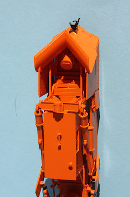
A less visible but important aspect of the ClassOne model is that it has roller-bearing trucks. The SP cars, however, were built with and long retained solid-bearing trucks (there is a photo of the SP Commonwealth truck for this class here: https://modelingthesp.blogspot.com/2023/10/the-new-class-one-flat-car.html ). 

There are various ways to alter roller-bearing trucks to the older type, but the simplest is to just file off the details that make them roller-bearing trucks. You can see that I’ve done this below, in the gray plastic areas.

Next, replacement journal boxes and covers needed to be added in each place that the roller-bearing end caps were located. I sliced these boxes off old plastic truck sideframes that for various reasons had been taken out of service, easy to do with a fresh razor blade. They were then glued onto the round gray areas you see above, using canopy glue. 

This isn’t really quite right, but does provide a non-roller-bearing look. For correct journal-box appearance, these should be a little larger. The prototype Class F journals were 6.5 x 12 inches, substantially bigger than the conventional 50-ton truck with Class D 5.5 x 10-inch journals.

With the work on trucks completed, it was time to paint the car body. I used Tamiya “Fine Surface Primer, Oxide Red” for this. There are those who inveigh against use of “rattle cans” for model painting, but they must not be familiar with the superior spray nozzle of Tamiya products. You do in fact have quite good paint control, and there are none of the “blorts” of paint often produced by cheap rattle cans.

Lettering is a challenge, obviously requiring piecing decal numbers. Here is a builder photo (SP) of one of the two SP cars in Class F-125-1, SP 39900 and 39901, taken outside the Algiers, Louisiana erecting shop where the cars were assembled. (You can click on the image to enlarge it.) Unfortunately, the car has not yet been weighed, thus the light weight and weight limit are not yet stenciled. New date is 3-53.

We can calculate the missing numbers. These were 125-ton cars, thus were equipped with trucks having Class F journals, as noted above. Such journals had a maximum-weight-on-rail capacity of 62,750 pounds per axle. That means that the car’s maximum weight on rail, the sum of the light weight and the load limit, would be 376,500 pounds. There exists a 1959 photo (p. 368 in Volume 3 of my series, Southern Pacific Freight Cars) of one of these cars, after the 1956 renumbering to SP 500501, which shows the load limit as 248,500 pounds. Subtracting the load limit from the maximum weight on rail means that the light weight was 127,500 pounds, which is consistent with what can just be read on a fairly dirty car side.

This is of course the classic example where no commercial decals (that I know of) exist to make lettering easier. For the 7-inch road numbers, I used the nice Microscale set #87-911, which is for wood box cars, but of  course numbers are numbers. The capacity data are more of a challenge, especially duplicating the numbers calculated above. I decided not to duplicate them exactly, but called on a used set I have, originally made for a Pennsylvania heavy-duty flat car. I was able to use other decal sets on hand to find lots of the other small lettering (or good approximations).

Once all decals were applied, I gave the car a coat of Tamiya “Flat Clear,” TS-80 (far better and more consistent than Dullcote, and with a far better spray nozzle than Rust-Oleum Testors seems willing to provide). You can see below that I either matched or simulated the small lettering too.

With the car lettered, and with a built date during my modeling year of 1953, I wanted to add just a light coat of weathering to tone down that “brand new” look. I went to my usual weathering process of applying washes of acrylic tube paints (see my “Reference pages” link at the top right of this post), including a fair amount of “grunge” on the trucks. I then added route cards and a couple of chalk marks.

Even though SP only owned two cars like this, I am happy to have an example, relatively easily converted from the new ClassOne Model Works car. I’m already working on some suitable loads for it.

Tony Thompson