Saturday, December 31, 2016

Progress at Santa Rosalia

I haven’t written about the town at the end of my mythical Southern Pacific branch line, which is Santa Rosalia, for some time. In fact, the last post about it described building Willow Lake Road (that post can be found at this link: http://modelingthesp.blogspot.com/2016/04/building-willow-lake-road.html ). But things have been progressing there, as I describe in the present post.
     That previous post showed the layout edge as raw plywood and Homasote. It did remain that way for some time, as complications in electrical power management delayed final arrangements. But finally I was ready to go ahead with some additional fascia to give the Santa Rosalia area a better look. As usual, I cut a piece of tempered Masonite and shellacked both sides before installing. Here is that piece, at the far end of the layout. The depot has been temporarily removed during work.


Note the bare spot at the left of the new fascia piece. The piece of L-girder sticking down below the layout edge is the support for a forthcoming control panel. The small black area on the fascia at right is a piece of Velcro.
     The small control panel will be for electrical management of the three-way turnout which can just be seen, right above the panel location. That electrical challenge is interesting in itself, and I will return to it in a future post. But for now, I am just discussing the fascia.
     I designed the control panel to fit in the empty space you see in the above photo. Without going into the electrical side of what is controlled, I will just describe the panel itself. I began with another piece of tempered Masonite, and painted most of it deep yellow. I then masked off what would be the track diagram on the final panel, using drafting tape.


This photo also shows the holes drilled for eventual layout attachment, at top, and the two holes for the control switches. The next step was to paint the panel black, and remove the tape. Here is the result at that point:


     For lettering, I simply laid out some yellow lettering on a black background, printed it out on heavy paper, and glued the resulting legends in the appropriate places. (I will describe the panel operation, and thus the labeling of the switches, in another post.) The panel could then be installed in the gap in the fascia, shown at the top of this post. In the photo below, the depot has also been restored to its regular location.


     Note here that I have added also the town name at center, so that visiting operators know which direction is east or west. (You can click to enlarge.) I also added the name of Willow Lake Road right under the road end. Any geographic feature which intersects the fascia, whether creek, road, or whatever, is named in this way, so operating crews know where they are.
     As I have done with other geographic features on the layout, I have chosen road and creek names from actual features in the area I model, even though there was no actual SP branch line in the area. Use of locally familiar names is another way to help “set the scene,” so to speak.
     This step completes the fascia in the Santa Rosalia area, and thus for the entire layout, since it is the last area being completed. I will return to progress here in future posts.
Tony Thompson

Wednesday, December 28, 2016

Locomotives for the layout

I have written several posts in the past about my choices for model locomotives to operate on my Southern Pacific branchline layout. One starting point for these choices has been the prototype SP locomotive assignment records (see my post at: http://modelingthesp.blogspot.com/2011/04/choosing-1953-locomotive-roster.html ). I followed up that post with one which showed more about those assignment records, and illustrated it with photos of one of my model locomotives, SP 2592,  which was chosen because of its assignment to San Luis Obispo (the post is at: http://modelingthesp.blogspot.com/2015/11/southern-pacific-locomotive-assignments.html ).
     In the present post, I want to show more of my model locomotives.One of them, SP 2829, is distinctive because it received a rectangular tender at one of its shoppings, a tender type originally assigned to SP Twelve-wheelers. Locomotive 2829 was assigned at San Luis Obispo for many years, and I have shown a prototype photo of it in a previous post (see that one at: http://modelingthesp.blogspot.com/2015/09/drawing-lines.html ). One reason I liked this engine is exactly that distinctive tender, and I borrowed such a tender from a brass Max Gray 4-8-0 so I could reproduce the look of SP 2829. Here it is in action, backing across Nipomo Street in my layout town of Ballard, as part of a switching move.


This locomotive, incidentally, often drew the yard job in San Luis Obispo, and as Mac Gaddis told me in an interview, the same “old head” crew ran the engine for years. The fireman on that job had one of those inimitable railroad nicknames; he was called “Numbnuts” (this interview can be found at: http://modelingthesp.blogspot.com/2011/01/modeling-freight-traffic-coast-line_19.html ). 
     Note that the previously mentioned model of SP 2592 also used a different tender than the one that came with that particular brass engine. Though a Key engine, the tender is a Westside product. The SP mixed and matched tenders, and modelers may have to do the same to produce a particular model locomotive.
     Also among the familiar San Luis locomotives were two of the Mikados assigned there, Class Mk-6 engines 3251 and 3264. The Mk-6 class was built by Lima in 1914. I have a model of 3251, converted by Al Massi from a Hallmark T&NO Mk-5 by adding a sand box, replacing the feedwater heater and changing some other details, to make it a Pacific Lines engine. I also had to do a tender swap on this locomotive, as the Hallmark T&NO version had a doghouse on the tender. I applied a 10,000-gallon Vanderbilt from one of the Consolidations mentioned above, which had themselves received new tenders. Here’s an Alden Armstrong photo of 3251 switching near the depot at San Luis Obispo.


     I use SP 3251 sometimes for the Surf Turn on my layout, though the turn was often handled by Consolidations. A common assignment of the San Luis Mikados was the King City turn, since they would have the power go up Cuesta, unless that train was light enough for a Consolidation to handle. But of course the Mikados were used elsewhere as needed. In this photo, 3251 is at Shumala on the Coast main line, just passing the depot as it arrives.


     The foregoing might sound like you have to do a tender swap for every SP steam locomotive, but of course that’s not so. One of the Class C-9 Consolidations I have on the layout, SP 2752, is yet another long-time denizen of San Luis Obispo, and had an entirely conventional 10,000-gallon Vanderbilt tender, which came with this Key brass model in the first place. Shown below is 2752 at the engine terminal in Shumala, with the caboose track in the foreground.


As with all my steam locomotives that have Vanderbilt tenders, I have relied on Al Massi to open up those tenders and install DCC and sound hardware. I owe him a real vote of gratitude for making these engines look and run as well as they do.
     This is not my entire locomotive fleet, but gives some idea of my choices for steam power, based on San Luis Obispo assignments in the early 1950s. Obviously I am assuming that power that worked on my mythical branch line at Shumala, only about 20 miles south of San Luis, would be drawn from the power that was assigned at San Luis Obispo. I have enjoyed researching that power, finding prototype photos of the engines in question, and then acquiring models to duplicate them for my layout.
Tony Thompson

Sunday, December 25, 2016

SP's Instructions to Station Agents, Part 5

This series of posts began with a description of the Southern Pacific document called Circular 39-1, entitled Instructions to Station Agents and issued by the SP Accounting Department. That description and some insights into SP waybill form numbers comprised that first post (it can be found at: http://modelingthesp.blogspot.com/2016/11/sps-instructions-to-station-agents-part.html ). Following that introduction, I have posted three additional sets of comments on various rules found in the document. They can be readily found using the search box just to the right on this page, using an appropriate search term such as “station agents.”
     An interesting part of the document relates to various issues in handling company freight, that is, materials owned by the SP and shipped between various on-line (or even off-line) points. I will begin with rule 1147. (You can click on the image to enlarge it.)


Unfortunately, waybill form 766 is nowhere described in this entire document, so I don’t know how different it might be from the standard waybill form. I have decided to go ahead and use the regular commercial waybill instead. Probably form 766 was intended to facilitate identification of the work order or job number for which the company freight was moved. I will return to this aspect in showing some model waybills, below.
     Here is rule 1149, giving some additional detail about handling of company materials (and materials belonging to other railroads).


Unlike the content of rule 1147, above, this rule provides that commercial freight rates would apply to such shipments.
     More indication that form 766 was set up for internal company accounting is given in rule 1154, and it also provides that an officer or employee must be shown as receiving any company freight.


     Finally, a fascinating provision for maintenance of way cars is shown in rule 1156, setting a nominal value for the weight of contents, and likely the particular maintenance job giving rise to a movement of MOW cars would be charged on such waybills.


     I have used some of the ideas about company freight in waybills on my layout. Track materials such as ballast and rail, as well as tools and supplies, can be waybilled to the track foreman at a particular location. Parts and materials can be shipped to the roundhouse machine shop in Shumala on my layout, and parts for repair, or scrap material, can be shipped out. I have also written waybills to move outfit cars, following what is shown in rule 1156.
     I will just show two examples here. First, an inbound load to the outfit track in my town of Ballard, directed to a specific employee, the B&B (Bridge and Building) foreman. The load in this case moves in a Maintenance of Way box car.

A second example is outbound scrap material for the machine shop at the Shumala roundhouse. I have seen SP waybills for scrap directed to the reclaim yard at Sacramento, so I think this is a realistic waybill, though not directed to a specific employee.


     These examples are just some of the company-material car moves which provide both interest and variety in my operating sessions. I plan to create more such bills in the light of the Circular 39-1 rules shown in this post.
Tony Thompson

Thursday, December 22, 2016

More on modifying Interstate Oil

I began this series of posts with some background on bulk oil dealer modeling and what I’ve previously written about it, and a start with modifications to the Walthers Interstate Oil kit, their no. 3006. Here’s a link to the first post: http://modelingthesp.blogspot.com/2016/12/more-bulk-oil-modifying-interstate-oil.html . As I stated there, I had decided to model a dealership for Richfield Oil Company, a familiar name in the Central California region I model in 1953.
     I began with the two structures in the kit, the warehouse and the pump house. Wall pieces for both were painted Reefer Yellow. I also then painted the sprues for doors and windows with a medium blue color. I used Tamiya TS-15. This blue is darker than the molded plastic window frames in this kit, and seems to me more like the dark blue ordinarily used by Richfield. Here is one of the warehouse sides with the blue parts installed.


     I like to make removable roofs for most of my structures, if there is any chance I might later decide to add interior lights or details. This is relatively little additional work, and I think the modelers who I sometimes hear expressing dismay at such a step, have not looked carefully at how easy it is to do. As I have shown before (see for example the roof for my depot at Santa Rosalia, as described at this link: http://modelingthesp.blogspot.com/2015/05/sp-depot-santa-rosalia-part-4.html ), I make a set of “roof formers,” styrene bulkheads with the correct roof pitch.These are then simply supported with short pieces of square styrene strip inside the roof.
     I begin by tracing the shape of the building end onto styrene sheet, in this case 0.030 inches thick (Evergreen no. 9030). Then I trace the end peak again, now upside down. Cutting out this strip, it looks like this:


There are two full “former” shapes here, along with two halves. The halves I splice together to make a third former, which will be plenty for a short structure like this one. Shown below are the two full formers, as cut out, a third one made by splicing (the splice plate is on the back of what you see here), and the building end for comparison.


     I selected, as I had commented in the previous post about this kit, a standing-seam metal roof to apply to the Interstate Oil warehouse. The roof was to be built from Evergreen no. 4523 material. I made the roof a little longer than the kit roof, since 38 scale feet was exactly a repeat distance on the Evergreen roofing. I made each side of the roof 15 scale feet wide. I used Evergreen 1/8-inch square styrene strip to brace the formers inside the roof. Here is the interior of the roof, with clamps holding it for glue to complete setting. (You can click to enlarge the image.) I find reversed clothes pins like these to be among my most frequently used clamps for modeling.


As all the styrene is white, this view doesn’t show the arrangement as clearly as I might like, but I think the overall idea can be recognized.
     The other decision for this kit is how to position the various elements (tanks, warehouse, etc.). I have enough space for this bulk dealership, but not the right shape space. I will re-arrange the tankage and maybe other elements so it can fit the space. After all, that’s what was done with prototype arrangements of tanks, too. This kit happens to have elements, like the horizontal tanks and the warehouse, which are on separate bases and can be grouped in a variety of ways. And of course the warehouse and truck loading rack both have to have road access.
     Arranging the elements, and more construction variations, will be presented in a future post.
Tony Thompson

Monday, December 19, 2016

The tank car tariff

I have often heard modelers who try to research tank cars and tank car fleets complain about the Official Railway Equipment Register (ORER), that most tank car owners don't show the number of cars in a number group. For example, an entry might be for cars 500–599, but the actual number of cars isn’t shown. And the overall size of that car owner’s fleet make it unlikely there are 100 cars in that group. But there is no way to know the actual number of cars.
     (For those not familiar with the Equipment Register or ORER, I wrote a four-part series of posts about it awhile back. In fact, those posts are actually parts of the essay I was asked to write as an introduction for the NMRA reprint of the January 1953 ORER issue. Here is a link to the fourth post in that series: http://modelingthesp.blogspot.com/2014/05/the-equipment-register-part-4.html .)
     The complaint I mentioned above is entirely accurate, and there is a simple reason why those data were largely omitted from issues of the ORER. It’s because there was a separate tariff document, called Freight Tariff 300 and entitled Tank Car Capacities Tariff. The tariff was reissued from time to time, and each time, given the next highest letter of the alphabet as a suffix. I will discuss below, for example, Tariff 300-H, from 1955.
     The first Tariff 300 seems to have been issued in the 1920s. Before that time, a similar document was in force, under several different names. For example, one series was called Circular 6, and it too had letters of the alphabet to indicate successive issues. Circular 6-O (that’s the letter “O,” not a zero) was issued in 1919, and has been digitized by Google. But for the most part, these tariffs are rare, found in very few archives.
     For some purposes, these documents are remarkable. They show the exact gallonage of every single tank car in service at the time, and of course the car number. One can obviously nail down any fleet of tank cars with this document. But for my purposes as a 1953 modeler, the 300-H issue, effective September 13, 1955, is excellent. Luckily for me, it has been reprinted. Here is the cover:


     The cover is a reproduction of the original book. The tariffs of this kind were not meant as lasting documents, because they were regularly replaced, and were printed on low-quality newsprint. This reprint is on good quality white paper. As you can see below, it is a sizeable book, fully an inch and a half thick.


     Where can you get this? Ian Cranstone has digitized two of these tariffs and has had them reproduced at Lulu.com as hardcover books. They cost about $42. The one shown above is the 1955; to buy it, go to:

http://www.lulu.com/shop/ian-cranstone/tank-car-capacities-1955/hardcover/product-22351502.html

Ian also digitized a 1936 issue, Tariff 300-A, and it can be purchased here:

http://www.lulu.com/shop/ian-cranstone/tank-car-capacities-1936/hardcover/product-22351796.html

     I will show one example of how this tariff can be used. Below is an AC&F builder photo of a California Dispatch Line (CDLX) car with four compartments, assigned to wine service. It was provided by Ed Kaminski.


     What can we find out about CDLX 931 from the ORER and from the tank car tariff? The ORER issue for January 1953 (the NMRA reprint mentioned above) only tells us that CDLX series 897–975 are AAR type TLI (lined and insulated) and with 40-ton trucks. A note to that entry adds that all cars in this series are “compartment cars,” meaning multiple compartments but not how many or how big. And as usual, the ORER does not tell how many cars were in this 897–975 number group (could be as many as 79 cars).
     The tank car tariff 300-H is from the summer of 1955, by which time the CDLX fleet had been sold to General American, and was in the process of being repainted and given GATX reporting marks. But there were a number of cars marked CDLX still in service, and part of a tariff page (page 266) containing some of the CDLX cars is shown below. (You can click on the image to enlarge it.)


     Here the four-compartment nature of CDLX 931 is clearly indicated, and the gallon capacity of each compartment identified. Note the other four-compartment cars shown also. The previous page in the tariff contained quite a few more four-compartment cars, along with a number of six-compartment cars. Moreover, the tariff shows that at that time, the CDLX 897–975 group contained 20 cars (and of course shows the individual car numbers).
     (Incidentally, anyone wishing more background on tank cars might wish to look at my two articles in Model Railroad Hobbyist, which were in the issues for February and March, 2016. The first is about prototype cars, the second about modeling. These and any issues of MRH can be downloaded for free, at any time, from their website at: www.mrhmag.com .)
     I find tank car models interesting and fun to operate, and naturally I have a fair number of them in my fleet to use on my layout. I often have occasion to refer to the tank car tariff for various kinds of information about the prototypes of my cars. I highly recommend it if you too find these kinds of information interesting. And a big thank-you to Ian Cranstone for making these available!
Tony Thompson

Friday, December 16, 2016

More bulk oil: modifying the Interstate Oil kit

In a previous series of posts, I discussed several approaches to modeling bulk oil dealers, an important rail-served business in nearly every small town in the transition era. My main project of this kind was a Tidewater Associated Oil dealer, using the Walthers kit called McGraw Oil as a starting point, though with a number of modifications and additions, and the concluding post about that project can be found at the following link: http://modelingthesp.blogspot.com/2014/03/more-on-associated-oil-dealer-model.html . I also described a smaller model of a Union Oil Company dealership, using an old Chooch kit with additions (see that one at: http://modelingthesp.blogspot.com/2015/09/modeling-union-oil-dealer-part-2.html ).
     Adjoining that Union Oil dealership is still a third oil dealer, minimally modeled, to which I can deliver the same petroleum products, but for Standard Oil of California. I described that modeling in a previous post also (see it at: http://modelingthesp.blogspot.com/2015/09/modeling-really-minimal-oil-dealership.html ). As I continue work on my final town on my branch-line layout, Santa Rosalia, I need yet another bulk oil dealer. I am certainly capable of scratchbuiling any part of such an industry, but might there be a kit which could provide some of the components conveniently?
     Among the most popular kits for a bulk oil dealer is the Walthers “Interstate Fuel & Oil” kit, their kit no. 3006. You see this on lots of layouts, making it perhaps a little too familiar to modelers. Here is a single example, from Lee Nicholas’s Utah Colorado Western layout in Corinne, Utah, a nicely installed example. (Additional photos of the layout can be seen here: http://modelingthesp.blogspot.com/2016/09/great-basin-getaway-2016.html .)


The five tanks are at the right, with the truck loading platform in front of them, alongside the road, and the round-roofed warehouse is across the spur, in front of the elevator.
     Now that I’ve studied prototype bulk oil dealers, my first question about any kit is, does it incorporate all the elements I described in my article in Model Railroad Hobbyist, and it does. It has a warehouse, enough storage tanks to be credible (and an interesting and realistic mix of horizontal and vertical tanks), a pump house, and a truck loading platform. (By the way, you can download my MRH article, which was in the March 2014 issue, or any issue, for free at any time from their website, at www.mrhmag.com .) But are all features of the kit desirable?
     Two things strike me immediately about this kit, that I wanted to change if I used it. First, the tanks have really big “weld seams,” excessive relative to any actual welding process. These would be easy if tedious to remove. (The lines are so big that one might even doubt they are supposed to represent weld beads, but the Walthers instruction sheet does call them “weld lines.) Second, the warehouse has a round roof, familiar perhaps with Quonset huts, but otherwise uncommon. That too could be corrected. I decided to buy a kit and see how it would go.
     My first objective was replacing that round roof. I simply cut the warehouse end pieces to removed the rounded parts, scribing with a single-edge razor blade and snapping. Here are the two ends, with the upper one already having its rounded part snapped off.


A wide variety of roofing could be applied to such a building, from shingles and rolled roofing, to corrugated and standing-seam roofing. I am leaning toward a standing-seam roof because there isn’t much of that type on my layout, but a final choice hasn’t happened yet.
      A decision that does have to be made early for structures, at least as I build them, is color scheme, because I prepaint walls and also details such as doors and windows. White or gray are common colors for bulk oil dealer structures, but this particular one for me will be a Richfield Oil Company dealer. Richfield used yellow and blue as corporate colors, and seems to have been determined to use them for all kinds of color decisions. I have seen several photos of Richfield structures which were mostly yellow. Shown below is a reproduction of a poster for the 2015 re-opening of a restored Richfield service station, with a period paint scheme of yellow, dark blue, and a red separating stripe. (There are several web sites with information about this particular gas station, such as: http://theoldmotor.com/?p=148277 ).


This image conveys a fairly soft yellow, but the corporate yellow was a pretty deep color, and photos of the Cucamonga prototype gas station, shown above, have a deeper color than this poster. I just like the poster for a good view of the entire structure.
     I will go ahead and use yellow as the main structure color, and add dark blue windows and doors. I don’t know that the band of second color around the building bottom would be used for an oil dealer, but will begin with yellow wall painting. I chose Reefer Yellow for the walls, as you see below on one of the sprues.


This sprue has the pump house walls, first four parts at lower left.
     As you can see, work on this kit is underway, and I will continue with my modifications in future posts. The parts of the work that comprise routine assembly, simply following kit instructions, will not be described, just the changes or variations I choose to make. These may give some readers ideas about modifying this particular kit, or more generally, may even just stimulate the willingness to regard a kit as a starting point for something else, not merely as a structure that you have to build in lockstep with the instructions. That’s something I’m still learning.
Tony Thompson


Tuesday, December 13, 2016

Op session testing

I recently wrote two posts about rebuilding a couple of turnouts on my layout, to manage electrical power routing with a Tam Valley Depot “Frog Juicer.” I will just cite the second of those posts, and it in turn provides a link to the first: http://modelingthesp.blogspot.com/2016/12/electrical-wars-part-12-new-turnout.html . One reason I needed to finish those two rebuilds was because I had an operating session coming up, which would be a good opportunity to test the rebuilding with a lot of operation.
     Last Sunday was the op session. It had been set up for a couple of Southern Californians, Al Daumann and Bruce Morden, who wanted  to come up to the Bay Area for the weekend and operate on Seth Neumann’s layout one day, and on my layout the other day. As it turned out, the whole weekend went well and we all enjoyed both the layout operations and the socializing.
     The first day was at Seth’s, and the layout is pretty well known; he models the Union Pacific in the south end of the Bay Area in 1999. The photo below shows him standing at Milpitas Yard on his layout, with the superb backdrop of a prototype photo of the actual hills you would see from that actual yard location. The rest of the 7-person crew is out of view.


     The second day was at my layout. I set up the operating patterns much as I would for any session, except that I did try to make sure there would be plenty of switching moves involving the rebuilt turnouts. This is just a matter of planning the car flow, something I do anyway. Here is one of the two operating crews, Seth (left) and Bruce Morden, working at Ballard.


     The rebuilt turnouts are on the other side of the layout (to the left of the backdrop in the photo above), in the town of Shumala. Here are Chuck Catania (left) and Al Daumann working their first shift at Shumala.


     As we have usually done, both crews worked on each side of the layout. After each crew has  completed the first round of switching, and after the Guadalupe Local operates on the main line, picking up outgoing cars at Shumala and delivering inbounds, the crews trade sides. The photo below shows Chuck and Al finishing up at Ballard.


     The crews did exercise the new turnout rebuilds extensively, and had absolutely no electrical problems, though track gauge needed a little adjustment in one of the turnouts. This was of course the goal, to get a lot of work through these turnouts. It is always an “acid test,” having visitors make a lot of use of something on the layout, to see how it performs. A few test moves by the layout owner cannot compare (in addition to the well-known principal that gremlins appear far more frequently or more severely when visitors are present). So I was glad to have a thorough exercise of the new construction, and it seemed to pass the test. Of course, we also had fun operating!
Tony Thompson

Saturday, December 10, 2016

SP's Instructions to Station Agents, Part 4

I began this series of posts with a general description of Circular 39-1, a document issued by Southern Pacific’s Accounting Department and entitled Instructions to Station Agents. You can read that initial post if you like, at this link: http://modelingthesp.blogspot.com/2016/11/sps-instructions-to-station-agents-part.html . One outcome from Circular 39-1, described in that first post, was understanding SP’s use of form numbers for the various kinds of freight waybills. I followed that post with additional material from Circular 39-1 concerning weight agreements, and showed how I use that information in model waybills (it is at: http://modelingthesp.blogspot.com/2016/11/sps-instruction-to-station-agents-part-2.html ).
     A third post in the series concerned information on waybilling of tank cars, something I have a fair amount of on my layout, and that post can be found here: http://modelingthesp.blogspot.com/2016/12/sps-instructions-to-station-agents-part.html . In the present post in the series I present several additional bits of information, all of which will show in my waybills, one way or another.
     I begin with rule 1048, which concerns cargo waybilled to a port for transfer to a ship. I don’t now have any such waybills, but some of my outbound loads could certainly be extended to cover such a destination. Here is the relevant part of the rule (you can click on the image to enlarge it):


I was intrigued that the rule states “Pacific Lines only,” since the Texas and Louisiana Lines served plenty of ports on the Gulf Coast, but my copy of Circular 39-1 had no corresponding entry for the T&L Lines.
     A related rule concerns cargo entering from Mexico. I was told some time ago that it was common for SP agents at border crossings to re-bill such loads, partly because some arriving waybills were in Spanish, and also because some arriving waybills only showed routing as far as the border. Here is the relevant part of rule 1025:


     A few other rules touch on the subjects of how certain customers’ cargo would be handled. These include Railway Express, which of course mainly handled express material in baggage cars, but almost anything could be shipped by REA, so the following rule 1033 applies to freight cars. This is another opportunity to write a standard freight waybill for REA cargo.


     Another special shipper was Western Union. The SP in many areas had its own pole lines and telegraph wires, but in a few areas ran its wires on crossarms attached to Western Union poles (obviously by arrangement). For that reason, Western Union crews often worked along SP tracks maintaining their own pole lines. Again, an SP rule, no. 1177, covered the movement of WU freight materials:


     Finally, when an SP employee in certain job categories was reassigned elsewhere on the system, a voucher could be issued to transport his household goods free of charge. The voucher was called a “dead-head order.” Here is rule 1031 for this situation:


     All these particular rules, though covering what are really details  in the world of waybills, are nevertheless interesting components of that world and can be incorporated into model waybills if a person wishes to do so. I am experimenting myself right now, and will show examples in a future post.
Tony Thompson

Thursday, December 8, 2016

Blog anniversary post

The first post to this blog was on December 8, 2010, so every year on that date I post some general thoughts about the blog. I also like to look back at topics covered and some of the numbers relating to viewers, both from the past year and overall. Last year’s anniversary post can be found at this link: http://modelingthesp.blogspot.com/2015/12/fifth-anniversary-of-this-blog.html . I should mention that the date of December 8 has no special significance; it simply happened to be the day I finished work on my first blog post.
     From the beginning, I have found the viewership data remarkable. Google’s Blogger application allows the blog owner to see statistics on page views, not only current views but over a week’s and a month’s span, along with all-time views. The first year there were about 50,000 page views, a huge number that was a complete surprise to me. But that was only the beginning. The following year there were about 100,000 more, and the third year about 150,000 more still. To me these were truly amazing numbers, with total views reaching about 300,000 views after three years. Thereafter the viewing flattened out quite a bit, with the fourth and fifth years each having around 170,000 new page views, but even so the totals after five years, of nearly 640,000 views, still seemed staggering.
     This sixth year has again seen an increase, with the annual number now in excess of 200,000 views, and representing further growth from what had looked like a plateau last year. You can see that in the screen shot below of the data. The graph begins at far left, at the line labeled “May 2010” (though I didn’t start posting until December 8) and runs until now. The “plateau” I mentioned is evident from the fall of 2013 through to the end of 2015. But it has really had some big peaks in page views during 2016, contributing to the record totals for the past year. And by the way, the large drop at extreme right just represents the partial return so far for this month, December.


Though I look at these numbers fairly often, I have never gotten used to their sheer magnitude. To me, it’s an amazing level of interest.
     My posting pace of a couple of posts a week continues to be about right for me. This leads to around ten posts a month, which I find comfortable. I have also had comments from people that they like finding new posts fairly often, so for at least some readers, the pace is good also.
     I have been receiving this year around the same amount of email comments and questions arising from my posts as in prior years. As has been true for some time, these are more numerous than comments posted to the blog itself. Though I like to see comments posted to the blog, because that way others can view the question as well as the answer, the email channel is fine with me, and represents another way I can convey information and in some cases, clarification. These queries usually touch on what I think of as the core topics of my blog: modeling the freight cars, trains and operations of the Southern Pacific, necessarily also reaching a wide range of associated topics like waybills, freight car detailing, and even railroad history, as a basis to understand modeling goals.
     I have been pleased that a relatively recent feature of the blog, the “reference pages” noted at the upper right of the adjoining boundary of the blog page, have been well received. These reference pages are a fairly detailed set of explanations and examples of weathering techniques, primarily using acrylic washes, mostly my own but some developed together with my late friend Richard Hendrickson. It is gratifying that modelers tell me they have gotten ideas, and seen how to carry out techniques, from these pages.
     I don’t really have any new goals for next year and beyond, though as my layout gets closer to completion, and my freight car fleet scarcely needs more cars, my thoughts and projects will be somewhat different than in past years. An obvious emphasis will likely be layout operation. Onward!
Tony Thompson

Monday, December 5, 2016

SP's Instructions to Station Agents, Part 3

In Part 1 of this series about the Southern Pacific Instructions to Station Agents, which was Circular 39-1 of the Accounting Department, I showed the appearance of the book and wrote a little about some of the interesting contents (you can see it at: http://modelingthesp.blogspot.com/2016/11/sps-instructions-to-station-agents-part.html ).In particular, I explored the SP form numbers for various kinds of waybills, and showed the ways I have implemented that information on the model waybills for my layout.
     The second section of this discussion, Part 2, was primarily concerned with information about weight agreements. For many shippers, those agreements simplified determining weights in freight cars, and I added some discussion about my knowledge of how weight agreements work and the various Weighing and Inspection Bureaus. Part 2 can be found at: http://modelingthesp.blogspot.com/2016/11/sps-instruction-to-station-agents-part-2.html .
     In the present Part 3, I turn to some interesting information in Circular 39-1 about waybilling of tank cars. Most of what I want to discuss is in rule 1028, and I show below four parts of that rule. (You can click on the image to enlarge it.)


          I will first discuss the main part of the rule, the first paragraph. This clearly provides that all privately-owned tank cars moving empty, whatever the.specifics of movement, cannot be moved on Empty Car Slips or equivalent, but must move on regular carload waybills. Among other things, this ensures that their entire empty movement is specified on one document, rather than the car moving through a number of junctions between railroads, all on the individual roads’ Empty Car Bills. This is something I have always done in my model waybills, as shown, for example, in Figure 15 of my column on waybills in the May 2012 issue of Model Railroad Hobbyist (you can download any issue of MRH at any time, for free, from their site at: www.mrhmag.com ). Here is another example.


In this case, the waybill to move the empty car returns it over the same route, via the same junctions, as the car moved when loaded, as the first part of rule 1028, above, requires. These waybills also conform to part (b) of rule 1028, requiring reverse movement along original route, and with the original shipper shown as consignee on the return. Incidentally, here is the model of car SHPX 4007 that is moved with these waybills:


The model is an Overland brass car, ICC Class 104, seen in my layout town of Ballard behind SP Consolidation 2592. In the background is a three-compartment wine tank car.
     Of course, tank car journeys can be much shorter, without traversing a series of junctions between railroads. The one shown below is at the other extreme of distance, though appropriate for my layout locale.


This pair of waybills is for the model of an asphalt tank car that I described in a previous post, part of my exercise in adding asphalt cars to my fleet (you can read it at: http://modelingthesp.blogspot.com/2016/10/asphalt-tank-cars-part-4-weathering.html ). Note also that the SP agent is shown as the shipper on the returning empty, as was typical practice.
     Finally, there is part (d) of rule 1028, mentioning that for tank cars owned by railroads (as opposed to private owners), an Empty Car Bill may be used, and the specifically recommended form is SP Form 1304. That form is the basis for my own layout Empty Car Bill, and that form number is in the upper right corner. Here is a bill pair to illustrate.


     I am interested in tank car movements generally, and perusal of SP’s rule 1028 from Circular 39-1 has helped me ensure that my layout tank car handling is prototypical. But there are still a few more valuable details to be gleaned from Circular 29-1, which I will take up in a future post.
Tony Thompson

Friday, December 2, 2016

Electrical wars. Part 12: new turnout parts

In the preceding post, Part 11, I described the electrical problems which can arise with an old Shinohara turnout, and a variety of ways to try and correct those problems (the post is at this link: http://modelingthesp.blogspot.com/2016/11/electrical-wars-part-11-better-power.html ). I should emphasize that the problems I enumerated are not characteristic of new Shinohara turnouts, but arise with age and oxidation of electrical contacts.
     That preceding post showed the removal of the point-rail assembly and cutting off of the closure rails, along with cleaning up the tie strip. The next steps were to install the new parts to replace the old, removed parts. The method described, I should explain, is suitable for turnouts already in place on a layout. Some of the required work is more easily done on the workbench, but usually one’s really old Shinohara turnouts are already installed in the layout. Work illustrated in the preceding post showed practicing on a turnout not installed, but the goal was to fix an installed turnout.
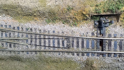
     As I showed in Part 11, all point rails were removed back to the area of the frog. The first step in applying new parts is to clean up the cut rail ends with a file, and install rail joiners that fit the rail size. This turnout in the SP main line on my layout is code 100, so that is the joiner size (you can click to enlarge).


This is a right-hand turnout, whereas some of the prior photos were for a left-hand turnout; but of course all the procedures are the same.
     Two pieces of rail, the code 100 size of the turnout, are now cut (overlength). One side is filed flat and the head of the other side also filed flat, to serve as points. Of course remember there is a “left-hand” and “right-hand” point, so don’t make the common error of making two alike (you can guess how I know). Then the stubs salvaged from the old point rails, as shown in Part 11, are soldered to the inside base of the point rail. Next a clearance hole is drilled in the stub to accept small assembly screws, such as 0-80, 00-90, or 1.2 mm (I used the latter). I will say more about assembly in a moment.


     I have a selection of small metric screws and metric tools (originally purchased to maintain brass steam locomotives), and these are nicely suitable for the turnout work I’m describing in this post. Shown below are the NorthWest Short Line packages of not only the screws, 1.2-mm panheads, but also the set containing a clearance drill, tap drill, and a 0.25-mm-pitch tap. These are not cheap but are fine for the job if you are not doing a great many of these tasks.


     Now the point rails, with the stubs attached, are used to locate the tap holes in a printed-circuit (PC) board throw bar. This is shown below, with the drilled hole extending through the new tie bar.


Next the hole under the second point is similarly located, of course setting the points at the correct spacing from the stock rails. The NMRA track gauge includes gauge tabs for this clearance, as shown below. You can see the overlength point rails at this stage, which can be cut to exact length after being attached to the throw bar.


Holes in the throw bar are then tapped and screws inserted. As always, a notch through the copper plating on the PC board throw bar is needed so there is no electrical continuity (and don’t forget the underside of the throw bar if you have PC board plated on both sides—don’t ask how I know).
     Some will say, why not solder the new point rails to the PC board? Anyone who has done this and then operated for awhile knows that eventually one or both solder joints breaks, because operation of the turnout exerts bending stress on that solder joint. And if you re-solder, eventually the copper may even de-bond from the PC board. Securing the points with screws prevents that.
     Now the correct-length point rails are inserted into the rail joiners and screwed to the throw bar. The assembly at this point still needs some more work, but the overall appearance of the new parts is clear.


To show a close-up of the screw heads and throw bar, the photo below shows this more clearly.


     An important step now is to use flexible wire and connect each stock rail to its adjoining point rail. This means the point rails are always correctly powered, and no longer depend on contact with the stock rail at the throw bar. Lastly, a new gap is needed next to the frog, which I cut with a cut-off disc in a motor tool.
     With all those steps complete, here is the rebuilt switch. The throw bar is not yet cut to length, or painted, nor are the new point rails painted, but you can see the completed arrangements.


The ground-throw obviously has not been re-installed, but that is a simple step.
     Now, as I stated in Part 11, I need to power the frog. This is an excellent spot for a Frog Juicer. As mentioned, these are made and sold by Tam Valley Depot (you can visit their site at: http://www.tamvalleydepot.com/support/whichfrogjuicer.html ). And with that, I now have a better-looking turnout which is electrically dependable without a lot of cleaning of the point rail contacts to the stock rail. I’m relieved and pleased! and I thank Jim Providenza for his help in working on my turnouts.
Tony Thompson