Sunday, April 30, 2023

More 3-D printed loads

 I have shown previously a number of 3-D printed loads that I have chosen for use on my layout. These are, I believe, only the thin edge of a wedge of considerable changes due to 3-D printing entering our hobby. Today I want to describe a few more loads 3-D printed that I recently purchased. For those interested, here is a link to a previous post about such loads: https://modelingthesp.blogspot.com/2020/05/impressive-flat-car-loads.html

As in the post just cited, and in others I have written about these 3-D printed loads (for example, this one: https://modelingthesp.blogspot.com/2020/06/blocking-for-big-loads.html ), these were from Multiscale Digital LLC (see their pages at: https://multiscale.digital/ and please note the photo on their home page of my flat car load of a Mesta crosshead!). 

They now market through Shapeways, and if you click on their “Shop Now” button, it will take you to the Shapeways pages, where you can place orders. Be sure to check the scale of an item before reacting to the price.

Two of the loads I recently purchased are shown below, in the as-received translucent resin. On the left is a “Loewy flywheel gearbox from Bethlehem Steel,” and on the right is a “double-volute split casing pump.” For scale, the pump is 13 scale feet long. And if the name of the Loewy load sounds familiar, it’s because I showed Eric Thur’s model of it in my Cocoa Beach report last January (it’s at this link: https://modelingthesp.blogspot.com/2023/01/cocoa-beach-2023.html ).

The flywheel load (left, above) I decided to paint a kind of “machinery green,” using an old rattle car I had on my workbench. Here I wanted to achieve something like Eric Thur’s version (see link, two paragraphs above). Here’s the prototype photo Eric showed with his model.

It’s interesting to research the Loewy name (easily done on-line), through their companies, primarily Loewy Hydropress, builders of some of the largest die-forging and extrusion presses in the world. Two brothers from Czechoslovakia, Erwin and Ludwig Loewy, started to work together for the Schloemann company in Dusseldorf, Germany. They left Germany for France in 1935. In 1939, Erwin left France for the U.S. and Hydropress Inc. was established in 1940. 

Below is an example of a Loewy hydraulic press at work (uncredited internet photo). 

Below I show this Loewy flywheel load on a Pennsylvania flat car, with most of the blocking done (and “DO NOT HUMP” placards at each end of the blocking). PRR 474273 is a member of Class F30A.

For the pump load, I began by painting it a medium/dark gray, for which I chose Tamiya “German Grey” (TS-4). A load like this would be heavy enough to need at least some blocking to restrain movement. But the mounting plates on the pump base would have been used also to bolt the pump to the flat car deck, so extensive blocking isn’t needed. I used scale 6 x 6-inch lumber to make some minimal blocking.

 I also made a foundry sign to accompany the load, though I don’t specifically know if this was a Bethlehem product. It’s photographed on W&LE flat car 1974.

The third load I purchased was an old-style transformer, suitable for either of my depressed-center flat cars. It is identified as a “1939 Allis-Chalmers power transformer.” It was made all in one piece. I decided to paint it a medium grayish tan. 

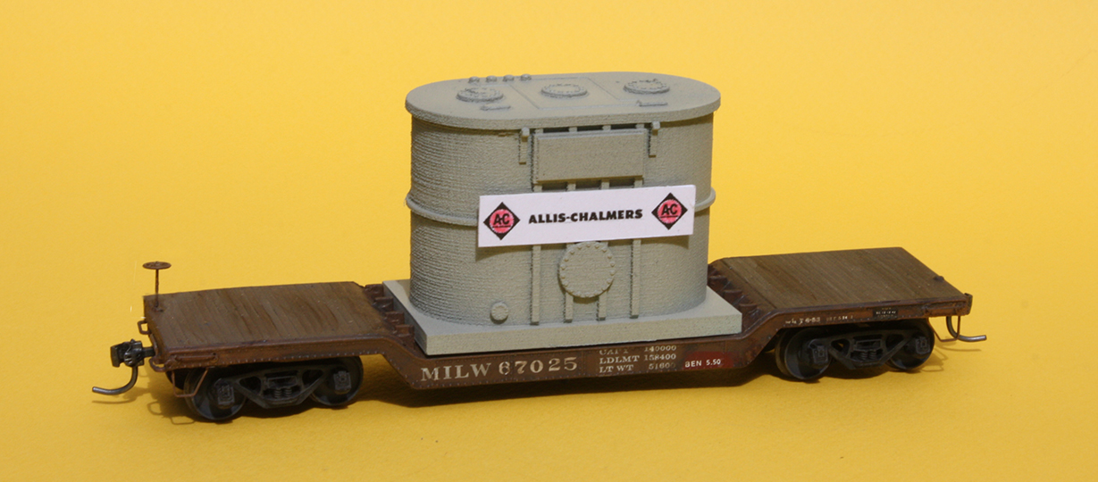
I also wanted to make a sign for the load. To find a good version of the Allis-Chalmers logo for my 1953 modeling year, I consulted this on-line source: https://theweekendhistorian.com/2012/07/04/allis-chalmers-trademarks-through-the-years/ . For versatility, I decided to make a different sign for the other side of the transformer, this one for General Electric, whose large transformer division at the time I model was in Pittsfield, Massachusetts. The familiar GE logo is readily available on the internet.

Here is the load on Milwaukee 67025, a railroad serving A-C’s home state of Wisconsin. The flat car is an ancient Devore white-metal casting (see my restoration description at: https://modelingthesp.blogspot.com/2020/08/restoring-devore-kit-part-2.html ), and models a 70-ton prototype.

Using the sign on the other side, the load can move on NYC 499056, a Walthers 90-ton car that I backdated to solid-bearing trucks, as I explained in a previous post (it’s at this link: https://modelingthesp.blogspot.com/2011/12/small-modeling-project-nyc-drop-center.html ).

These are interesting additions to my “fleet” of open-car loads, where variety is always welcome. Loads like these are distinctive enough that I don't want layout operators to recognize loads as ones they’ve seen many times. Having more of them on hand obviously helps prevent this.

Tony Thompson


Thursday, April 27, 2023

Waybills, Part 109: still more stamps

In the preceding post, no. 108 in the series, I showed my creation of a Canadian weight agreement stamp. Just like American ones, this identifies a weight agreement between a shipper and a Weighing and Inspection Bureau or WIB. These agreements allowed a shipper to simply count units loaded and multiply by the unit weight, so the car did not need to be delayed to be passed over a scale. (That post is here: https://modelingthesp.blogspot.com/2023/04/waybills-part-108-more-stamps.html .) 

Recently a friend, Bill Jolitz, provided me with nice, clear images of WIB stamps that I had not seen before. By this I mean individual agreement numbers in the stamp center, not the WIB itself. They were from the Eastern WIB and the Western WIB. As I showed previously, we know the territories of the six U.S. tariff organizations that hosted WIBs (see that post at: https://modelingthesp.blogspot.com/2021/05/waybillls-part-85-more-on-weight.html ).

But the maps shown in the post just cited only emphasize two of the WIB territories, Eastern and Southeastern. The Western WIB region, shown below in green, encompassed a large piece of the United States, the entire states of North and South Dakota, Minnesota, Wisconsin, Iowa, Missouri, Nebraska and Kansas, along with the northern third of Illinois and the eastern third of Colorado. Note that in this case, the name “Western” does not mean Far West; the Far West shown below was under the Transcontinental Freight Bureau.

Below I show the WWIB stamp image that Bill provided. I like that it’s a very clear and distinct image of the stamp in question. It’s also formatted differently than the WWIB stamp showed in that previous blog post (link in the second paragraph, above). I do like to have variations in what I put on model waybills.

But this format, with the legend in the center, “shippers weight under weight agreement” and the agreement number, does appear to be pretty standard. You can compare a number of such stamp images in one of my previous posts (see that at: https://modelingthesp.blogspot.com/2021/02/waybills-part-79-weight-stamps.html ).  

Bill also provided me a stamp image from the Eastern WIB. As I showed in my post about maps (the with the link in the second paragraph, above), the Eastern territory was not large, but encompassed a really intense industrial area of the United States in the transition era. Here is that territory, repeated from that map post:

And here is the stamp image Bill sent. Again, this seems to have been a standard stamp format, widely though not universally seen.

As attentive readers of this blog will know, I already had images of stamps from these two WIBs, for the WWIB and the EWIB, but slightly different in format and with different weight agreement numbers. This makes further variation among my model-usage waybills. For example, here is a waybill for an inbound load to an industry on my layout, using the new stamp:

Adding the weight agreement stamp to a waybill is very prototypical (for appropriate cargoes), and something I enjoy including on the waybills used on my layout.

Tony Thompson

Monday, April 24, 2023

ProRail 2023

 The annual ProRail (Prototype Railroad Operations) event this year was in Kansas City over the weekend just past. And it was in that city for a good historical reason: this is the twenty-fifth year since the second-ever ProRail was held there. This follows last year’s ProRail in Chicago, marking the twenty-fifth year since the very first ProRail event was held there. (For more on the history, you may visit the site: http://www.prorail.org/history.html .)

I attended, along with a group of Bay Area modelers, and as we often do, enjoyed some additional layouts in the MidWest before the event in Kansas City opened. I was especially pleased to have a chance to visit the recently-retired and newly settled Doug Harding in Iowa. He has quite a nice big basement, and has been able to make a permanent set-up of his long-portable layout, which represents the M&StL in, where else, Iowa.

Below you see Doug, making a track repair on a part of very recently laid track, with Jim Providenza doing yard work in the background. I really enjoyed this large layout, with a bunch of interesting and distinctive towns, and I know how pleased Doug is to have a place where the layout doesn’t have to plan on yet another move in the near future.

From Doug’s house, south of Des Moines, we headed west on Iowa Highway 92, avoiding for the moment the heavy traffic on Interstate 80 to our north. This was really delightful driving, little traffic and lovely farm country (though spring was just cautiously poking its nose into the scene). We started seeing signs with directions to covered bridges off the highway, which seemed odd until we passed a sign reading “Madison County.” Aha! Those bridges. 

So we thought we really ought to go see one, and did so in Winterset, Iowa. While there, a helpful passer-by took a photo of our crew in front of our really big Ford “Expedition.” From left, we are Jim Providenza, me, Bryn Ekroot, and Seth Neumann.

We were on our way to Omaha, where several layout visits were scheduled. The first was Steve Rodie’s outstanding layout. It has a lot of fine operating features, though many areas are as yet unscenicked, but the backdrops are as good as you will see anywhere. The double-decks visible below are a good example. 

The locale is Montana, and of course these are photo backdrops. Steve has done a great job of choosing just where the bottom of the backdrop can be blended into future scenery, while keeping great skyline and sky views with real clouds. Seeing these photographed clouds reminds one of the limitations of trying to paint things that look like clouds.

Unfortunately, for me, that was the end of a few days of operating. I came down with a fierce stomach virus in the night, and was basically out of commission until Saturday. Let me interject here that, as I’ve observed on this blog before, I really don’t want there to be a “personal diary” character to these posts. I just mention the health issue because I don’t want to seem to be ignoring the fine layouts at which I was scheduled to operate in those intervening days.

On Saturday, though, I was kind of back in commission, and joined the “Expedition” crowd at Lynn Masoner’s layout depicting the Bay Area car float operations among SP, WP, Santa Fe, and the Alameda Belt Line. It’s basically two layouts, with the landlocked WP and Santa Fe trackage in San Francisco on one layout, and across the Bay, the SP and Alameda Belt. Three of the railroad’s operations feed car floats, and the local industrial switching is proto-freelanced. Here’s a view across the Alameda Belt Line’s car float, toward the WP operation in the distance.

In the photo above, you see a long white structure at right. This is the back of a pretty darn good representation of the distinctive Del Monte cannery in Alameda, which makes a great signature structure for a layout like this.

Set in the 1970s, the switching is intense and quite interesting. I did get to spend a little time with a Proto Throttle, and much enjoyed it, as I have with that throttle in the past. Thanks to Lynn and his co-conspirator in building the layout, Dan Munson, and Lynn’s gracious wife Sue, for hosting us. It made a good wrap-up for ProRail 2023.

Tony Thompson

Friday, April 21, 2023

Modeling SP passenger cars, Part 14

In the present sub-set of this series of posts about passenger cars, I am addressing the modeling of Southern Pacific streamlined sleeping cars. I began with background and some prototype photos of two particular floor plans, 4-4-2 (4 compartments, 4 double bedrooms, 2 drawing rooms) and 13 DB (13 double bedrooms). I had already obtained car sides for these two floor plans from Brass Car Sides, as I showed in that initiating post (see it at: https://modelingthesp.blogspot.com/2023/03/modeling-sp-passenger-cars-part-12.html ).

In the following post, I showed the modification of my target car body for one set of these sides, and the attachment of the 4-4-2 brass sides. My target was a Rivarossi streamlined coach (these models were originally imported from Italy by AHM, Associated Hobby Manufacturers). That post can be found here: https://modelingthesp.blogspot.com/2023/04/modeling-sp-passenger-cars-part-13.html .

One point I mentioned in the first of these posts (cited in the first paragraph, above) is that these particular Brass Car Sides products were intended for an Eastern Car Works body, not the AHM body, and accordingly were just a bit too short for the AHM car. My solution was to go ahead and attach the sides, with one end flush at the vestibule end of the car, and then to fill the gap at the other end with styrene sheet of the same thickness as the brass car sides, 0.010 inch.

Incidentally, the Brass Car Sides are drilled for handrails at this end of the car, as you may be able to see in the image above (to enlarge this image, you can click on it). The SP cars like this had only a horizontal handrail at this end of the car (often called the “blind end” since there was no vestibule there). The photo below of a 4-4-2 at San Francisco in August 1953 shows this (Lawson K. Hill photo, from SPH&TS Volume 2 on Sleeping Cars). You can enlarge this photo by clicking on it, if you wish.

You may also note in this photo the appearance of cars with original full-width diaphragms removed and most of the full skirting removed. Note also where the road name lettering has to be positioned on account of the upper berth windows on this side of the car. Finally, it’s visible in this photo that the dark window band did not extend across the vestibule door at the far end.

Turning now to modeling the 13 DB car, the AHM car body that I had on hand for this one was a “1930 sleeper,” a 10-6 floor plan, but of course most of the windows were in the wrong place. I opened up window openings just as I had in the instance of the 4-4-2 (see post 13, linked in the second paragraph above). I should mention here a point I’ve made before, that the Rivarossi plastic is quite soft and easy to work, so much so that I would caution against removing too much material if you’re not careful. 

I think the bedroom side of this AHM 10-6 model had the greatest window discrepancies with the corresponding brass car side of the four sides to be replaced in this project. It’s shown below in its cut-up state. But even this state of the plastic body still provides lots of gluing surface to attach the brass sides.

The same procedures used on the 4-4-2 car worked equally well for this 13 DB car. The first sides I attached, using canopy glue and the modified clothes-pin clamps, as before, was the aisle side of the car to be created.

Then the last of these attachments of brass sides was the bedroom side of the 13 DB car. Here again, the glue process and the clamping worked well. The final step was to add the styrene filler at the blind end on each side, as was done before (see first photo in the present post). In the image below, the upper car shown is the aisle side of the 4-4-2, the lower car is the bedroom side of the 13 DB.

Finally, I began to plan the painting process, intending to decorate both cars as Lark sleepers. My layout includes a short segment of the SP Coast Route, so cars of this kind did operate, both in the Lark itself and in other trains as movements were needed (there are numerous photos of cars being deadheaded in either direction to rejoin their train after shopping). So a coat or two of paint is what’s next, and I’ll treat that aspect in a following post.

Tony Thompson

Tuesday, April 18, 2023

Another Bill Welch freight car

I mentioned in a previous post that at this year’s Cocoa Beach meeting, some of Bill Welch’s unfinished or damaged car projects were distributed by Ted Culotta to modelers willing to do what was needed to  repair or complete them. One that came to me was a CGW box car (see the previous post just mentioned, which was about that car: https://modelingthesp.blogspot.com/2023/02/a-bill-welch-freight-car.html ).

I also received a car project that was substantially built, but not finished. It was a Tichy styrene kit for a rebuilt USRA box car, of which Bill had completed all the fussy parts (as most of us would see them), drilling all the holes for grab irons and installing them, and installing a full arrangement of brake gear. He had also painted the car. The underbody is shown below, obviously without wheelsets and couplers.

Bill had not added any weight to the model. The Tichy floor has two molded spaces on top (which will be inside the car) for 1/2-inch steel nuts. I added them, and a third one in the center, with canopy glue. This brings the car weight up to four  ounces.

The body was, as I stated, essentially complete, with detailing very well rendered, a trademark of Bill’s modeling. It was also painted and lettered. It did lack a brake wheel, and he had omitted some of the running board boards, intending to add “replacement” new boards. Note also that he had already added paint patches for reweigh and repack lettering. My intent was to accentuate these and add weathering (and those missing boards).

My first step was to add Kadee no. 158 whisker couplers in the coupler boxes, and to install InterMountain “semi-scale” wheelsets in the truck frames. I also washed the car roof, which had evidently stood for some time on a shelf, and dust had semi-bonded to the paint.  Then I could mate the body and underbody, and add a brake wheel.

With that done, I proceeded to finish the lettering, adding reweigh data and a repacking stencil. I also added the test stencil on the air reservoir, plus a route card on the route card board. Some intermediate light weathering has also been done, but a little more will be added. 

Finally, I wanted to fulfill what Bill had set out to do, and add some unpainted replacement boards in the running board. Simplest way to represent unpainted wood, of course, is to use scale stripwood, which is what I did, scale 1 x 6-inch size, attached with canopy glue. I believe this appearance, with unpainted replacement boards, would have been unusual, but it’s nice to have one example in my fleet.

I enjoyed working with this incomplete project of Bill Welch’s, partly because of my great respect for Bill as a modeler and a person. I look forward to seeing this car in switching moves on my layout.

Tony Thompson

Saturday, April 15, 2023

Modeling in O scale, Part 4

 In this part of my little journey through O scale model railroading, I want to talk about re-doing one of Larry Kline’s freight cars. This is the brass gondola model that he picked up at an O Scale West meeting. I showed it in my first post on this topic (see it at: https://modelingthesp.blogspot.com/2023/02/modeling-in-o-scale.html ). I mentioned in that post that I wanted to re-do the car.

The gondola is a decent model of a prototype Enterprise design circa World War II, a type that Southern Pacific did purchase, their Class G-50-16. Here is the car as it came to me (shown also in the post just cited):

The lettering is mostly in the wrong places, is a mixture of lettering that probably never was together at one time on a gondola, and with the large sans-serif road name and post-1956 car number, would in any case not fit my early 1950s modeling preference. 

Here’s a view of the prototype, not in its as-delivered paint but with a post-1946 repaint, when the spelled-out road name became the reporting mark (Paul Dunn photo, 1947, Rich Burg collection). For more about SP’s post-war GS gondolas, see Chapter 7 in my book Southern Pacific Freight Cars: Volume 1, Gondolas and Stock Cars, Signature Press, 2002).

My first step was to overpaint the entire car. I used a light gray primer over the sides, to reduce the contrast of the lettering underneath, then a finish coat of Tamiya “Red Brown” (TS-1). This color is a little browner than what modelers traditionally think of as boxcar red, but is within the range of variation from railroad to railroad. Note below that I left one side panel un-repainted: it contains a correct-size SP emblem, correctly located. 

A nice feature of brass construction is revealed in the internal end corrugations, the “inside” of the Dreadnaught end, at the far end of this view.

This paint gives a semi-gloss finish that isn’t shiny but is a good surface for decaling. I went directly to the Protocraft O-scale set of Rick Leach decals for SP post-war gondolas, “SP G-50-15/22.” I chose the post-war scheme, as on the prototype photo above, for this car. The 300 cars of Class G-50-16 were numbered SP 95200–95499.

Next I added route card boards above the left truck on each side, using stripwood, and painted the boards. Next step was to weather the entire car, inside and out. If nothing else, I wanted to tone down the striking white of the new lettering. I used my usual acrylic-wash method, as described in the ‘Reference pages” linked at the top right corner of the present post.

You’ll note above that in addition to achieving the dusty look I wanted, shown under an overcoat of flat finish, that I also added a few chalk marks and route cards. This completes the car project. 

This was, for an HO scale modeler, quite an experience with a really large model, and definitely fun to do. It won’t convert me to O scale, but it increases my respect for and enjoyment of that scale.

Tony Thompson

Wednesday, April 12, 2023

Better model dome platforms, Part 2

A couple of years ago, I showed the background for the need of better dome platforms on those of our model tank cars that should have them (you can see that post here: https://modelingthesp.blogspot.com/2020/09/a-better-model-dome-platform.html ). 

That post, which introduced a dome platform kit from Yarmouth Model Works, was a follow-on to earlier efforts of mine on this topic (for example, this post: https://modelingthesp.blogspot.com/2015/05/another-approach-to-tank-car-platforms.html ), efforts to replace the Athearn platform.

The prototype platforms, as I’ve shown before, have very light-looking components, completely unlike the long-familiar Athearn platform on what Athearn calls a “chemical tank” car.  I show one below, to emphasize the extremely fat corner posts and oversize height and length of the platform. It’s not only oversize for HO, it is actually a bit oversize for S scale (except for the posts, which have no known equivalent).

There are a number of alternatives, as I’ve often mentioned on this blog, but today’s topic is further work on a really nice product. Yarmouth Model Works, in their kit YMV-360,  offer an excellent fret that can be folded up to make a really far better platform. My introduction of the kit is in the post linked in the first sentence of the present post.

In that post, I showed a Yarmouth fret folded up for use, and indicated I was starting on a couple of tank cars to use these platforms. One obstacle for me is that both of my project tank cars have fairly large conventional expansion domes, not the smaller, slender valve bonnet that is found on pressure tank cars. That’s a potential issue because the Yarmouth frame is hardly bigger than such expansion dames, making the preparation of the platform floor challenging.

Or so I thought. Like so many things, I worried about how to do it for far longer than it actually took to do it. First point I recognized was to use fairly thin styrene sheet for the platform, to make it easier to cut a round hole in a square platform. I used 0.020-inch thick scribed sheet. I chose that because in the prototype, until 1948, most tank cars has wood planking on the dome platform, not the metal grid material familiar in later years.

Second, I didn't have a simple way to lay out the dome diameter on the styrene platform. Or so I thought. Both of my domes are less than 0.75 actual inches in diameter, and I realized that that is just about the diameter of a U.S. five-cent coin. So I could use a nickel coin for layout, and cut inside of its diameter.

Then I played around with the folded fret and the new styrene platform, and immediately realized that the flimsy-feeling platform, which I was worried would be delicate, actually can be quite strong: if you just glue it to the platform, it’s held square and flat. Nice! Below, the platform is just resting on the frame, not yet glued. You’ll notice that the nickel coin happens not to be in the center of its platform.

The usual practice on tank car dome platforms was to orient the planks crosswise to the car, so I did that also. Then I glued the fret around the outside of the platform, using canopy glue. 

The Yarmouth recommendation is to use 0.015-inch wire for the handrails. However, this really is not correct in prototype terms. Both the side handrails on tank cars, and the handrails on dome platforms, were always specified as 1-1/4-inch nominal iron pipe size. But this is just a nominal dimension, not the pipe diameter. As you can readily discover on the Internet, the outside diameter of such pipe is in fact 1.66 inches, close to 0.019-inch wire in HO scale. 

But the arrangements of the Yarmouth parts are for the 0.015-inch wire, so I decided to build my first shot at the project that way, and made sure the platform holes were fully open, clearing them with a no. 78 drill. I began by installing the plain horizontal handrails, using phosphor bronze wire from the Tichy Train Group.

Here the railings are attached with canopy glue, which I’ve learned is quite tenacious. With those side railings in place, I experimented with how to make a consistent curvature in the railing pieces that are on either side of the platform entrance. I used the sharpened part of a wood pencil for a mandrel, and once I had four reasonably identical parts, attached them also with canopy glue. They were made oversize, and the excess lengths simply clipped off after the glue had set. 

You can see above that the railing parts aren’t entirely symmetrical, but this was a learning experience. Perfection not necessary in this case because with the platform finished, I painted it dark gray for this tank car, and dry-brushed it with Polly Scale “Grimy Black.” Moreover, please compare the photo just above with the Athearn monster shown at the top of the present post.

Here is the installed platform on the destination tank car, with side ladders yet to be installed.

For purposes of comparison, here is a similar-size tank car (though insulated), built in 1940 by American Car & Foundry (AC&F builder photo, courtesy Ed Kaminski) and leased to the Heyden Chemical Company. Note that the platform railings look a little heavier than the model above, doubtless because of the undersize wire used with the Yarmouth parts. But the general impression of the model platform is quite good.

Overall, these Yarmouth parts are really nice, and I will be building more of them for others of my tank cars that need a better platform.

Tony Thompson

Sunday, April 9, 2023

Koester’s book on McClelland and the V&O

 Many by now will have seen the new book from Kalmbach about the late Allen McClelland and his Virginian & Ohio layout, by Tony Koester. Like all of Koester’s book, it’s really well written and well illustrated (with considerable help from McClelland before he passed away), but more importantly, it does a great job of conveying all the things Allen pioneered. And just as this book brings together Allen’s achievements, it’s well to remember that it was Tony’s championing (when he was editor of Railroad Model Craftsman) of Allen’s modeling and ideas that first created everyone’s appreciation of Allen McClelland and the V&O. 

This is the customary Kalmbach Books (now Kalmbach Media) softcover format, 8.5 x 11-inch upright format, 112 pages, with their customary price point, $21.99. It’s very nicely produced and easy to read, an excellent example of how this kind of book can be done right. And I’m grateful for the book because my copy of the Carstens volume about the V&O is pretty well worn! (My own appreciation of Allen’s contributions and that book is in an earlier post, at this link: https://modelingthesp.blogspot.com/2022/11/remembering-allen-mcclelland.html .)

Allen of course did pioneer or champion a lot of things, and Tony devotes chapters to several of them: walk-around throttles, extensive use of everyday plastic models, choice of plausible, not dramatic, effects, seeing the model railroad as part of a system, and of course the famous “good enough” principle. I expanded on some of that in my prior comments (link in previous paragraph).

The “good enough” idea I think is sometimes misunderstood as meaning that you don’t have to do great modeling. Well, it does mean that, tangentially, but the more important meaning is that the entire layout is supposed to be done, and every part of it done to the “good enough” standard. In other words, it’s not enough to build a few “good enough” freight cars and feel like you’re in the “McClelland groove.”

Recalling the 1970s, when the V&O was new to a lot of people, I know one thing that was a little surprising to many was that it was unapologetically a coal-hauling railroad. One shortcoming of the new book is that it has few photos of Allen’s coal trains. I show below an image of the terminal at Afton on the V&O (there is a mirror making it look bigger), but at least it shows a string of hoppers.

The book features an atmospheric photo of the V&O at Fullerton, Virginia, taken by Jim Boyd, and I vividly recall when this was first published. It’s not a super-detailed scene — hardly anything on the V&O was — but the atmosphere was superb. Living in Pittsburgh at the time, I had driven around a lot in rural West Virginia, and Allen certainly captured the feel of that region in this scene.

Not mentioned particularly in the book is that Allen was a darn good photographer. Of course he knew the scenes and feelings he wanted to capture on the layout, but the point is that he could accomplish that. The scene below, an overtaking train at Dawson Spring, used also for the cover of the book (though cluttered up with other graphics there), is as good an example as there is. This just is Appalachia.

Speaking of photos, one of Allen’s images is used twice inside the book. I’ll pose it as a challenge to readers to identify it. 

I really liked Allen, whom I had gotten to know when living in the same NMRA region with him, seeing him at regional conventions, and visiting his layout. This book is a great tribute to a great modeler and pioneer in our hobby, and also a fine piece of history of the hobby. I can’t recommend the book enough, and I believe that the less you may happen to know about Allen McClelland right now, the more you will learn and enjoy by perusing this book.

Tony Thompson

Thursday, April 6, 2023

Waybills, Part 108: more stamps

 I have in a number of posts described my efforts to add rubber stamps, or the images of stamps, to my model waybills. This is for the simple reason that rubber stamps of various kinds appear on most prototype waybills. To illustrate, I will show just one, from the collection of Andy Laurent, a bill for a load of newsprint paper originating in Ontario on the Ontario Northland Railway in Canada.

The stamp of interest for the present post is the large round one about mid-height in this image, just to the right of center. It’s a weight agreement stamp, for the Canadian Freight Association, Eastern Lines. There are other interesting features on this waybill, including the customs clearance and the notation, “customs papers attached,” but I will focus on the weight agreement stamp.

In my previous posts (beginning with: https://modelingthesp.blogspot.com/2020/10/waybills-part-73-creating-rubber-stamps.html ) I have described the process of creating the stamp images, so won’t go into detail. Basically, the scan such as the one above can be cleaned up in Photoshop and all background parts of the form removed, and an image of just the stamp can be achieved. Here is the stamp image that results from the Ontario Northland waybill:

Once a clean image of the stamp is accomplished, I use the “layers” feature of Photoshop to add a transparent layer below the layer with the stamp image. Then I select all the white parts of the stamp image and delete them, leaving just the black parts on a transparent background. This allows the stamp tiff to be placed onto a waybill and only the black parts are added.

To illustrate how this is used, I show below a waybill from my layout for an arriving loaded car that originated in the eastern part of Canada and has cleared customs. Whether the routing shown via Huntington, British Columbia is realistic, I don’t know; perhaps a reader can correct me.

I should mention that there was also a “Western Lines” stamp for the Canadian Freight Association, which I showed in an earlier post about weight agreement stamps (see it at: https://modelingthesp.blogspot.com/2021/02/waybills-part-79-weight-stamps.html ). Its format is fairly different from this Eastern Lines one.

Though I have not seen an explicit description of how Canada was divided into Eastern Lines and Western Lines, I infer from a map of national freight bureau territories that I included in a previous post (find it at this link: https://modelingthesp.blogspot.com/2021/05/waybillls-part-85-more-on-weight.html ), that the divider was the 90th meridian, in western Ontario, at the western tip of Lake Superior. If anyone can correct that interpretation, please do so. 

I showed in an earlier post the creation of a customs stamp like the one shown in this model waybill. I have noticed in Andy Laurent’s waybill collection that a variety of such stamps can be seen, suggesting there was not a standard stamp of this kind. In fact, the customs stamp on the Ontario Northland waybill above is an example; it reads, “RELEASED FROM CUSTOMS AT SAULT STE. MARIE, MICH.” I will likely make some more customs stamps to give variety to my own waybills. (You can see my first post on customs stamps at: https://modelingthesp.blogspot.com/2020/10/waybills-part-74-more-stamps.html .) 

Tony Thompson


Monday, April 3, 2023

Modeling SP passenger cars, Part 13

 In the previous post, number 12 in the series, I addressed some possibilities for modeling Southern Pacific streamlined passenger cars other than the familiar 10-6 floor plan which is available in plastic from Rivarossi (see that post at: https://modelingthesp.blogspot.com/2023/03/modeling-sp-passenger-cars-part-12.html ). And just to repeat, these models were imported from Italy by AHM. The procedure I described was to use the fine parts from Brass Car Sides.

I decided to proceed with the more challenging of the two floor plans I have set out to do, the 4-4-2 (meaning 4 double bedrooms, 4 compartments, and 2 drawing rooms). I showed a prototype photo of such a car in SP service in the previous post (cited above). I decided to start with a Rivarossi streamlined coach for this car. The reason it’s more challenging, as shown below, is because of the two small upper-berth windows in each compartment on the bedroom side of the car.

One approach to adding the brass sides to a plastic car like this might be to remove the original sides entirely, and attach the new sides instead. But as I mentioned in the previous post, it may be preferable to remove only the parts of the window band in the plastic car, any parts that would show through the new windows. That retains considerable stiffness in the car body, and was my choice.

The Rivarossi coach shown below (the same one shown in the previous post, cited in the first paragraph) has been modified as described, so that new side windows will have none of the old body behind them, but as you can see, the upper and lower sides are still well connected and sturdy. This will be the aisle side of the new car.

In this photo, you can not only see the window changes on the nearest side of the car, but through the windows you can see some of the modifications underway on the far side, which will be the bedroom side of the completed car. Just visible at the top of the car side is a narrow lip, which will be the locating line for the brass sides. 

The other side of the car was modified in much the same way, but with the complication of those upper-berth windows. My first plan was to cut out a strip of material from the car side where the upper-berth windows are located, then I began to think I would be better off to make just a hole for each window, instead of a long, weakening opening.

That was the procedure I followed, first drilling a hole of about #50, then using small files to enlarge the holes into a rectangular shape like those small windows. I continually checked progress against the hole shape and location in the brass car side, until I thought they were a good enough match. I took a photo of the car side at this point to show what all 8 holes in the upper side sheet looked like.

My next step was to glue the brass sides onto the modified car body. Since this action glues brass to plastic, I used canopy glue. It’s an excellent adhesive for dissimilar materials like this, and has the further advantage that it remains both tenacious and flexible. That means that temperature excursions, in which one component may change dimension more than the other in response to temperature change, will not cause the parts to separate.

I have modified a number of wooden clothes pins so that they are kind of a parallel-jaw clamp, rather than a small-area clamp like the original. Below is the aisle side of the car, receiving its brass side. The narrow lip at the top of the plastic car side is visible here; it formed a very helpful alignment edge for the new side. You may note that I removed the short segment of brass underbody skirt at the right end of the car side. 

Although canopy glue adheres quite well in an hour, I like to leave a joint like this under clamp overnight.

Next came a repeat of the actions shown above, but on the other side. Again, I removed the short skirt segment at the non-vestibule end of the car, so that the original AHM carbody skirt can take its place. At the other end, I gently rolled that skirt segment to get curvature matching the AHM body. And again, canopy glue was the adhesive, and the modified clothes pins were the clamps.

With both sides of the 4-4-2 car now attached to the AHM body, I will turn to the 13 double-bedroom car and bring it to the same state: almost ready for paint. That way I can paint both cars together. There are a few issues with paint application, the final handrail details, and decals, but I will address those in a following post.

Tony Thompson