Friday, August 30, 2024

An Athearn “Blue Box” tank car, Part 3

 This series of blog posts is about using many of the parts of an Athearn “Blue Box” tank car, with the insulated tank body, as the starting point to represent a particular prototype tank car, a Shell Chemical Company high-pressure car I showed in the previous post in the series (see it at: https://modelingthesp.blogspot.com/2024/07/an-athearn-blue-box-tank-car-part-2.html ).

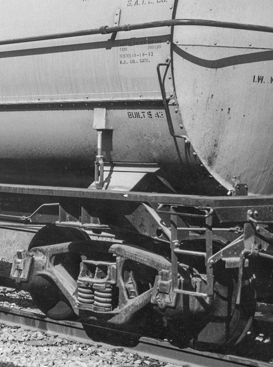
At the end of the previous post (just cited), I had prepared the Athearn bottom sheet part for addition of the turnbuckle hold-down of the tank bands on the car. Below is a repeat of the close-up prototype photo from the previous post (link shown above). You can see that part shielding the emergence of the tank band from under the jacket is right at the longitudinal joint in the jacket.

My intention was to make the cover shield parts, then add turnbuckles. For the cover shields, I began with an Evergreen styrene scale 8 x 8-inch strip, and drilled a #75 hole through it near the end. I then carefully cut off the approximate cube containing the hole, from the end of the strip, and in turn carefully cut the cube at a 45-degree angle. A couple of these parts are shown below. Any parts that don’t come out properly are readily replaced with better ones.

Next these parts were glued to the bottom sheet, right at its top edge (see prototype photo for location), and aligned with the bolster position, as molded into the bottom sheet. 

These are now ready for turnbuckles. The Tichy parts, no. 8021, are cored for 0.0126 wire, meaning that 0.012-inch wire will fit nicely. These need only be short lengths. I cut the wire pieces over-length, glued them into one end of the turnbuckle with canopy glue, then cut the wires to the correct length and glued the wire into the shield pieces,again with canopy glue. I did this with the bottom sheet inverted, as you see below, so that the wire ends were inserted vertically.

The bottom sheet modeling work is now completed, and as soon as work on the upper tank is finished, the two parts can be painted together. I’ll describe all that in a future post.

Tony Thompson

Tuesday, August 27, 2024

The Railroad — What It Is, What It Does

Many readers will recognize the title of today’s blog post as the title of a book by renowned layout designer John Armstrong. This book, The Railroad — What It Is, What It Does, was first published in 1978 (Simmons-Boardman, Omaha), and though that date is long after the steam era, the book does contain considerable information about railroad practices well back into the steam era.

Here is the front cover of the original edition (soft-bound, like nearly every subsequent printing). It is 6 x 9 inches and contains 240 pages. Notice the sub-title: “The Introduction to Railroading.” That was the purpose of the book, and a purpose it has continued to fulfill.

In a number of ways, this is a remarkable book. Its breadth and depth continue to impress me, even after using it for quite a few years as a reference. I feel quite confident in stating that no matter how much you know about any one area of railroading, you will find information here that you didn’t know.

It is important to recognize that the book was a great success for Simmons-Boardman. It has been revised several times and reprinted many times. It remains in print today, and is still given to new employees on at least two of today’s railroads to give them background. 

 I also have the Second Edition, from its fourth printing of 1988. It is not enormously changed, having been revised in 1982 from the original book (written in 1977).

And of course each successive revision has removed the oldest information and terminology, and replaced it with new, along with adding new subjects as appropriate. I mention that because today’s book is significantly larger and quite different from the 1978 original. Obviously your chosen modeling era will determine whether you want the oldest edition, or one of the later ones.

John Armstrong passed away in 2004 and thus the most recent edition did not benefit from his hand. Today there is a Fifth Edition, issued in 2008, and now grown to 406 pages. If you would like to get this book, it is available directly from Simmons-Boardman for $49.95, though on-line booksellers are offering it for higher prices in some cases. I haven’t seen this edition myself.

John had been trained as a mechanical engineer (Purdue) and worked most of his career at the Naval Ordnance Laboratory in the Washington, DC area. After retirement, he was a consulting editor for Railway Age magazine for ten years. As many readers will know, he was renowned in model railroading for his layout designs and for his O-scale Canandaigua Southern layout (he was born and raised in Canandaigua, New York).

His layout design ideas have been very influential, best known probably through two of his Kalmbach books, Track Planning for Realistic Operation (Kalmbach, Milwaukee, 1963, 2nd Edition, 1976), and Creative Layout Design (Kalmbach Books, 1978). He published 76 articles in Model Railroader magazine in his lifetime, greatly extending the recognition of his ideas.

When I give talks about layout operation, or waybills, or rules of freight car handling and movement, I always show a slide of this book, and recommend it to the audience. It is the authority I rely on to make sure I am correct about any aspect of the prototype. It is clear and easily understood, even on arcane topics like switching districts or milling-in-transit waybills. If you want to understand any aspect of prototype railroading, I cannot recommend this book highly enough,

Tony Thompson

Saturday, August 24, 2024

Chromite ore shipments on my layout

 I’ve written several posts in the past about chromite mining in the area I model, the Central Coast of California. The first issue for me, and for anyone modeling a specific mining area, is to find out the prototype facts. I wrote a fairly general introduction about this, emphasizing how anyone could follow the kinds of leads I followed to learn about mining history in the area I model. That post is here: https://modelingthesp.blogspot.com/2016/10/modeling-mining-in-your-locale.html

I then wrote about modeling suitable ore cars, and suitable loads, to represent this ore traffic, in a Part 2 of the post just cited. In that post, I showed the crushed green shale I have used to represent a disseminated chromite ore (read it at: https://modelingthesp.blogspot.com/2016/10/modeling-mining-part-2.html ). This ore was too low of a grade to be used for refining to chromium metal or ferro-chrome alloying additives, and was typically used as a component in refractory brick.

In a third, more recent post, I repeated some of the background on chromite, and showed a few of the ore cars that I have placed in service. As I prefer to do in most of my open-top cars, the loads are removable. (See: https://modelingthesp.blogspot.com/2021/10/chromite-mining-on-my-layout.html .)

I was aware that by the 1950s most chromite mining in California was “pocket” mining on a small scale. I also faced the problem that there wasn’t space on the layout to install a mine scene. Solution? Assume ore is trucked from mine to rail. Then a truck dump would be the way that ore cars would be loaded, and this is also a compact kind of industry. 

I did have minimal space alongside Bromela Road in my town of Ballard, and built up a small incline that could perhaps serve as a truck dump. The truck helps identify what it is. The dump is by no means high enough to get close to direct dumping out of trucks into a railcar, so a conveyor would be needed.

So despite its obvious limitations, this preliminary attempt does suggest the activity. Then, in an operating session, a loaded ore car alongside the “dump” looks all right. A switch crew can pick up this car and understand its origin.

I have for some time kicked around ways to make this more realistic. A low truck incline is all right, if trucks can dump into a receiving bin, which in turn is emptied via conveyor into a railcar. But the space alongside Bromela Road is terribly narrow to model all that. Another possibility would be to load the ore cars at a team track, a logical place for truckloads of ore to arrive. Most of my team tracks have ample space to model a loading scene.

Note in the above photo that I show a GS (General Service) drop-bottom gondola being loaded. In one of my interviews with Mac Gaddis, he mentioned gondolas of actual chromite, a much denser material than the disseminated ore I am modeling. (See Mac’s comments at: http://modelingthesp.blogspot.com/2011/01/modeling-freight-traffic-coast-line_19.html .) But either ore could be loaded on my branch.

I am still toying with the idea of kitbashing the Walthers Truck Dump kit (their number 933-4058) into something I could use at a team track. I am a firm believer in Tony Koester’s admonition, “Don’t look at the name or picture on the box, just use the parts you need to make what you want” (from his fine book, How to Kitbash Structures, Kalmbach Books, 2012). If I get sufficiently inspired to do that, I’ll report on it in a future post.

Tony Thompson

Wednesday, August 21, 2024

Blue flags and lockouts

The title of this post may be baffling to some readers, but it refers to track safety measures: placement of blue flags to identify when a track may not be entered, or a piece of equipment may not be moved. As it applies to tracks, this is often called “locking out” a track. By rule, such a blue flag may only be placed by an authorized employee, and when placed, can only be removed by the employee who placed it. This is of course to avoid misunderstandings about the status of the blue flag. For more about the prototype background, see: https://modelingthesp.blogspot.com/2017/04/blue-flags.html ). 

On my own layout, I enjoyed researching prototype blue flags, and creating brass models of them, for use on the tracks on my layout that might need them. (The post describing my building of the models is here: https://modelingthesp.blogspot.com/2017/04/blue-flags-part-2-modeling.html .) Below is a photo of one of these new blue flags in use. (It reads: Caution Tank Car Connected.)

But I soon learned that scale-size flags like these, especially with their medium-darkness color, were easy for crews to overlook, and in several operating sessions, switch crews simply drove over them. Since they are brass, they can be repaired easily, but that isn’t the point. I needed another way to make crews aware of the presence of the flags.

As part of my recent trip to the Chicago area for an operating weekend, I enjoyed another visit to Bob Hanmer’s fine layout. I wrote a few highlights from the visit, among several other layout visit descriptions (see the post at: https://modelingthesp.blogspot.com/2024/07/an-operating-weekend-around-chicago.html ). But a really interesting point about the session at Bob’s was the process he uses for track lockouts.

As I showed in an earlier post, he devised a form which allowed a crew setting out a car, with a known time interval for the car to be “blue flagged,” to add that time to the set-out time and identify when the car could be picked up, for their own later use, or use in a following operating session. (That post is here: https://modelingthesp.blogspot.com/2018/10/blue-flag-awareness.html .) Here’s another view of Bob’s form, from my most recent visit:

Since I don’t operate with a fast clock (my layout clock is 1:1), the way Bob implemented his lockouts would not work the same way on my layout. What I initially did instead was to create a form to provide the ending time of a lockout. I showed that form and its use in a previous post (see it at: https://modelingthesp.blogspot.com/2019/02/blue-flag-awareness-part-2.html ). Here’s a repeat of an illustration from that post:

The defect here is that this only identifies the ending time of a lockout (appropriate for instances when the local agent has been notified by the industry of when the car can be released). But it doesn’t capture the span of lockout times, as the Hanmer form does. 

So I gave some thought to what a Hanmer-type form could accomplish in one of my operating sessions. It could certainly add a duty to the crew setting out a car at a siding subject to lockout: they have to fill out the form with the spotting time. And of course it also can notify them when a car can be picked up, just like the form shown above.

For purposes of trying out this idea, I shamelessly copied the Hanmer form, removing its Great Northern identifier. Since I model the Southern Pacific, which on many of its forms did not include the railroad name, such as train orders, clearance cards, switch lists, telegram blanks, and many others, I decided I could use the form as-is. Here is how it looks for now.

I will include this form in future operating sessions and will see how well it works, and will experiment with both set-out and pickup requirements for crew interaction. Then I can modify the form as seems appropriate. Thanks again to Bob Hanmer for the idea.

Tony Thompson

Monday, August 19, 2024

Waybills, Part 116: early prototype examples

I have by now written quite a few posts about using prototypically-oriented waybills in model railroad operations. (For a guide to the first 100 of these, see this post: https://modelingthesp.blogspot.com/2022/11/waybills-part-100-guide.html ). Waybill history is among the topics I’ve discussed through this series, and today I want to show some interesting prototype examples.

Original waybills of all ages are not commonly found among railroad paper, and that’s especially true for examples before, say, World War II. But this post will show several prototype waybills, copies of which were given to me by Richard Townsend, that date from the early 1920s. All are from the Coudersport & Port Allegany Railroad. 

This 39-mile railroad, located along the upper stretches of the Allegheny River in northern Pennsylvania, not far from Olean, New York, had three connections to the outside world. In Port Allegany itself, they connected with the Pennsylvania Railroad; at Ulysses, PA, with the New York Central; and at Newfield Junction, PA, with the Buffalo & Susquehanna. These connections are reflected in the waybills.

 Here is one of them, a load of lump charcoal in bulk (un-bagged), loaded into Erie 102966, a 36-foot, 40-ton box car. The shipper, as for all of these bills, was the Gray Chemical Company of Roulette, PA, located a few miles west of Coudersport. The car was to be moved to Newfield Jct. to interchange with the B&S, then onto the Erie for movement to New York and the consignee, P. McNamee Charcoal Co. of Brooklyn. Note, as was the case on many, many surviving waybills, the rate has been corrected, in this case after determining actual weight at Wellsville on the Erie.

A second example, this one with a Pennsylvania car being loaded at Roulette with lump charcoal, is destined to the Schoenling Bros., on Eggleston Avenue in Cincinnati. The car, PRR 39336, a Class X26 single-sheathed box car (the USRA design), will be interchanged with PRR at Newfield Jct. and weighed on the PRR at Olean, NY. 

A third example, showing use of a New York Central car for this same cargo, bulk charcoal from Gray at Roulette, will be interchanged to the NYC at Ulysses, PA, en route to the Taylor Chemical Co. at Cascade Mills, New York. The car, NYC 161722, was a double-sheathed 40-foot box car of 40 tons capacity. And like all these waybills, this was a copy, not the original that traveled with the car.

You may have noted that in each of these waybills, the Car Service Rules were well followed, with cars of the destination railroad being loaded for shipment.

Finally, there is a good example of a privately-owned tank car being returned using a regular freight waybill, to permit its prompt return to the owner. The tank car, SSLX 30, was one of 312 tank cars operated by Semet-Solvay at the time, and was a 6000-gallon car. It was to be interchanged to the NYC at Ulysses, PA, en route to the Solvay Process Co. in Solvay (near Syracuse), NY.

The C&PA remained independent for many years, serving its lumbering and leather tanning territory until, cut back to 26 miles length, it was purchased in 1964 to become part of the Wellsville, Addison & Galeton Railroad.

Lastly, I should mention that K4 Decals offers a decal set for a Gray Chemical 8000-gallon tank car. (You can see all their tank car decals at this link: https://k4decals.com/collections/tank-car-decals , and you can choose the scale you want.) They are nice decals, and I am considering whether to letter a tank car that way. If so, I’ll return to the topic in a future post.

Tony Thompson


Friday, August 16, 2024

Early HO scale couplers, Part 2

 In my first post on this topic, I described a number of the early couplers available in HO scale, from the Varney dummy coupler (an accurately shaped and sized coupler), to the other extreme, the Mantua loop coupler, and the good-looking but not very reliable Devore coupler. You can read that post here: https://modelingthesp.blogspot.com/2024/07/early-ho-couplers.html .

If you do read that post, you’ll find a discussion point by my friend Arved Grass, stating his belief that the initial Kadee metal coupler was the model MK. As I replied, that’s not true. It certainly is true that the MK coupler was the first Kadee magnetic coupler, and it was first advertised (as far as I can determine) in the December 1959 issue of Model Railroader, or MR.

But years earlier, the Kadee metal coupler head had been introduced, with a variety of coupler shanks, with model numbers from 4 to 7 (and later to 10), all called “K” couplers, not MK (probably “K” stood for Kadee). These had a straight trip pin, as you can see below (ad from page 12, October 1956 MR). I imagine the “good lookin’ ” phrase was with reference to the Mantua loops.

Or for a view of several cars with these straight pins, there is this photo (page 46, October 1957 MR):

And just to cinch the point, here is Kadee’s announcement of their new Model 10 or K-10 coupler (the same one shown above) for Athearn’s plastic freight cars, but in a very clear drawing (page 16, July 1957 MR):

In the previous post about early couplers (link in top paragraph of the present post), I had misremembered what the Kadee uncoupling ramp was like. I thought it was a converging throat to push the pins together. Actually, it was the opposite: a diamond shape that pushed the pins apart to uncouple the couplers. It could be raised electrically. Here’s a photo (page 41, May 1957 MR):

There were the familiar types K-4 and K-5 “for general use,” as the ad below says, along with several other types for specific rolling stock, up to type K-8 (ad from page 7, May 1956 MR):

But finally they did introduce the “Magna-matic” coupler, the one we have used ever since. As mentioned above, I believe this is the initial announcement in the December 1959 MR, page 25; it isn’t obvious here, but this coupler has the curved trip pin that is so familiar now.

So the straight-pin Kadees were all “K” models, and didn’t become “MK” (as shown above) until the end of 1959, when the above announcement was published. In what I hope isn’t  excessive clarity, this should now be a complete story.

Tony Thompson

Tuesday, August 13, 2024

More on HO automobile license plates

Every layout has at least a few vehicles on it, and from the earliest days of the 20th century in the United States, license plates have been issued to such vehicles, from almost the beginning by individual states. To me, that means that vehicles on my layout should not only have license plates, but the correct ones for the year I model, 1953. I’ve written about this before (see, for example: https://modelingthesp.blogspot.com/2012/11/vehicle-license-plates-in-ho-scale.html ).

In the post just cited, I gave links to the history of California license plates (and mentioned that every state appears to have such history on line somewhere). And in a subsequent post, I showed the prototype license plate which was newly issued by California in 1951 (here’s the post: https://modelingthesp.blogspot.com/2022/12/era-and-locale.html ). This original license plate hangs in my layout room and I often point it out to visitors.

But that isn’t the entire story. In that era, California, like most states, only issued new metal plates every several years, and during the years in between, issued something to reflect current registration for that year. In California’s case, it was a little metal corner tag, attached with the bolt in the lower right corner of the full license plate. This covered the year of the underlying plate, “51”  in the example above, with the current year, and naturally in a contrasting color each year. For 1953, it was white, and I have an original one of these also.

For modeling purposes, one could of course start with real metal license plates and digitize them to construct HO scale images; it is easier to use the digital images from the on-line history sites. That is what I have done, as described in the post linked in the second paragraph at the top of the present post. Here’s an example of the kind of image I reduce to HO scale and print out on paper with a copy shop’s high-resolution printer:

The paper license plates are cut out and attached to vehicles, front and back, with canopy glue. So wherever a vehicle may be on my layout, as in the example below, which is on Chamisal Road in my layout town of Shumala, passing the Dolphin & Anchor tavern, it has the correct license.

I should also mention that California had a separate series of license plates for trucks, both light and heavy trucks (and they still do today), which were similar but with different numbering. I’ve written about model truck licenses previously: https://modelingthesp.blogspot.com/2012/12/vehicle-license-plates-trucks.html .

I continue to occasionally acquire a new vehicle for my 1953 layout, and before it appears on the layout, it will definitely acquire a correct license plate. It’s a small detail, but one that contributes to identifying the layout’s era.

Tony Thompson

Saturday, August 10, 2024

Operating off-line passenger cars

On most railroads, back in the days of passenger service, the railroad’s own passenger cars (other than sleeping cars) would form the consist of most if not all passenger trains. A major exception was jointly operated trains, when equipment from two or more railroads operating the route would be a normal sight in the trains. The other exception was sleeping cars.

Pullman-assigned sleeping cars, prior to 1948, were usually painted and lettered for the host railroad. But there were exceptions, such as when a railroad would have requested (rented) extra equipment from Pullman to handle a convention or some other special occasion, or when a railroad’s car had been damaged or even wrecked, and Pullman might temporarily supply a stand-in. Rail photographers loved to get shots of this kind of event, so probably we have more documentation than is statistically correct. Still, these events certainly did occur.

Here’s an example on the Southern Pacific, shown in the SP Historical & Technical Society book on sleeping cars, Volume 2 of the series Southern Pacific Passenger Cars (Lou Cross photo). New York Central 10-6 (10 roomettes, 6 double bedrooms) Perch River is at Oakland in 1949, one of the “through” cars in Overland service. There were also Pennsylvania Railroad cars in similar service, and also photographed in Oakland,

Similar views of off-road passenger cars were seen in Los Angeles, for cars that had moved over the Sunset and Golden State routes, particularly from the Missouri Pacific roads and both Illinois Central and L&N.

As most modelers with prototype interests know, the world of passenger railroading was greatly changed in 1948, when Pullman was obliged by an anti-trust suit to divest itself of either its passenger carbuilding business, or its ownership and leasing of passenger cars. It chose to sell the latter, and in a somewhat complicated financial dance, a great many of its cars were sold to railroads that wanted them, at book value.

Each railroad naturally chose many of the Pullman-owned cars that had been built for that railroad’s specific trains or specific needs, along with a certain number of additional cars for expected needs. All would then be lettered for the owning railroad. The unsold ones remained with Pullman, and many, regardless of paint scheme, then might appear in temporary assignments all over the country.

Although such cars were not frequent on the Coast Route, they did appear. Below is a good example, a Paul Lukens photo from Ryan and Shine’s excellent book, Night Trains of the Coast Route. It shows a New York Central 4-4-2 sleeper on the rear of the San Francisco-bound Lark, and ahead of it, two Budd 10-6 sleepers, one SP and one UP. All three are deadheading. The photo is well captioned as, “The Pullman Pool at work.”

I decided to model a couple of cars like this. One is a Rivarossi streamlined sleeping car (a 10-6), an Illinois Central car in its distinctive orange and brown paint scheme. Like I have done with other Rivarossi sleepers, I added view blocks, weight inside, and both face plates and stabilizer rods to the diaphragms, with body-mount couplers and replacement Central Valley trucks added after this photo (for the procedure I followed, see: https://modelingthesp.blogspot.com/2024/06/modeling-sp-passenger-cars-part-20.html ).

Another car that can play this deadheading role is my Pennsylvania 10-6 sleeper, Stoney Rapids, from Walthers. Below you see this car at the back of a deadhead move, sandwiched between SP 9106 at right, a 13 double bedroom car, and SP Clover Mountain at left, an 8-5 car (8 sections, 5 double bedrooms).

These off-road deadhead movements add variety to the limited passenger traffic I can depict on my small segment of the SP Coast Route. And I enjoy depicting this little slice of passenger railroading history.

Tony Thompson

Wednesday, August 7, 2024

Operating empty open-top cars

It occurred to me on a recent trip out of town for an operating weekend, that many layout owners seem to avoid having empty open-top cars. Now of course if you model heavy coal or ore traffic, you naturally have big cuts or even full trains of empties running in the opposite direction of loads. But ordinary flat cars and gondolas are seen empty far less often.

I understand part of this, because a lot of the interest in modeling flat cars and gondolas is that they can carry really eye-catching loads. Heck, I like those too (as you can see in many post posts on this blog, such as: https://modelingthesp.blogspot.com/2023/04/more-3-d-printed-loads.html ). But I like realistic car movements too. This is one of the drawbacks to loads installed permanently in cars: the car can’t run empty.

Statistics from the AAR (Association of American Railroads) in the early 1950s reveal that more than a third of all freight cars moved homeward empty (depending to some extent on car type). Open-top cars should thus be seen with at least one-third frequency in an empty condition.

In a normal cycle on my layout, the most common sequence is a loaded open-top car spotted, for example at a team track. This Western Maryland gondola with a load of pipe is an example, in my location of East Shumala.

In the following session, presumed to be a day or two later, the local switcher picks up the empty, which will be sent to the nearest (off-layout) yard.

But mainline trains should reveal the presence of such cars too. On my layout, the main line that is modeled is the Southern Pacific’s Coast Division, and through freight trains do pass by during an operating session. Here’s an example, using one of Richard Hendrickson’s models with lots of dunnage from the previous load still on the deck.

Of course, the loads in–empties out sequence that I illustrated at the outset of this post isn’t the only event, at least on my layout. The Santa Rosalia Local often spots empty gondolas at the Jupiter Pump & Compressor plant for the shipping of large crates. Here’s the local preparing to spot such a car, which happens to be an SP gondola.

I do try to remember that empty open-top cars ought to be part of the operating patterns, and plan my layout sessions accordingly. I believe it’s a more realistic program.

Tony Thompson

Sunday, August 4, 2024

Model building

I recently received an interesting and challenging comment via email about the context of my recent series of posts about modifying a Rivarossi observation car as a stand-in for a Southern Pacific business car, SP 119, assigned as the Superintendent’s car for SP’s Coast Division during the era I model (1953). I made it clear that I was only modeling the prototype car in broad brush strokes. You can read the concluding post at this link: https://modelingthesp.blogspot.com/2024/08/operating-sp-business-car-conclusion.html  .

The remark that came to me was about my “slackened” standards in doing such modeling. This really brings up a far more general topic, about model building in general, and what is the purpose of the models we build. That’s what I comment on in the present post.

Like most if not all modelers, I certainly build occasional models with the intent of stretching my skills to their limit, and getting all major and many minor details exactly right. Usually these are models of Southern Pacific equipment, the prototype I model. An example would be my project to model an automobile car of SP Class A-50-17 (for a description, see: https://modelingthesp.blogspot.com/2015/01/modeling-sp-class-50-17-conclusion.html ). Here’s a photo:

Other times I only want a representation of a prototype, and I often refer to such models as “main line” models, meaning you will only see them on my layout in a passing train on the main line. The business car referred to above is definitely in that category. Freight cars of some railroads that I don’t find very interesting may also be built as “main line” cars.

Even cars of that kind are worth weathering well and making sure that the most obvious parts of the model, notably the roof, would withstand at least a somewhat close-up view. Then they look good even in a passing train. 

I am always surprised when I visit a layout and see rolling stock with little or no weathering. You may not wish to weather as thoroughly as my late friend Richard Hendrickson often did, but this can certainly raise the credibility level of even a simple model. Here’s one of Richard’s meat refrigerator car models.

Most of my models, however, are much more accurate than the “main line” cars and will withstand scrutiny from a fairly close viewpoint, as in switching moves near the layout aisle. This especially applies to freight cars of the SP and of Pacific Fruit Express. Are these and the main-line kind of models in conflict? I don’t think so.

I suppose the extreme case is the contest model (or a model built to standards that would allow it to perform well in a major contest). I was an NMRA contest modeler for a number of years, and then graduated to contest judging for both regional and national contests, and finished that phase of my modeling career by serving five years as Contest Chair for NMRA’s Pacific Coast Region. I think it was valuable for me to learn the kind of research, discipline and application needed to succeed with this kind of modeling.

Still, I well remember chatting in a contest room with a group of contestants and judges, and one of the contestants mentioned that he was starting to build a layout. One of the others immediately remarked, “So I guess we won’t be seeing you in the contest room any more.” This encapsulates the choice most of us have to make, between building exquisite individual models, and creating, scenicking and operating a layout.

Where I come down on that choice is quite obvious from many posts in this blog, about numerous topics having to do with my layout, and frankly, equally so for my description of models like the business car, SP 119. Such choices are, after all, to some extent purely practical ones in terms of available time and effort.

I will continue to devote varying amounts of effort to different models. That doesn’t mean “anything goes;” on the contrary, I have long had a self-defined “floor” under quality (see for example my posts about standards; here is one example: https://modelingthesp.blogspot.com/2023/07/standards-for-layout-freight-cars.html ). Final results will always depend on personal choices.

Tony Thompson

Thursday, August 1, 2024

Operating an SP business car, Conclusion

In the previous post, I completed what I want to say about the prototype SP 119 official car, and showed the beginning of my work to modify the model closer to the prototype. You can visit that post and its material at: https://modelingthesp.blogspot.com/2024/07/operating-sp-business-car-part-2.html .

I felt one of the aspects of the Rivarossi model car that I could change in the direction of the SP car was to move the rear wall out to the end of the car sides, instead of maintaining a “deep” platform compartment. In the previous post cited above, I showed the removal of the wrongly located wall.

My next effort was to sand the edges of that wall section down to fit, and then re-insert it at the end of the side walls, where it fit snugly and was secured by wetting the joints with styrene cement. Note in this view that the profile of the canopy over the platform is level, thus no need for a small awning at the center, as seen on the prototype SP 119.

The body that I have came with a molded interior. The first thing I wanted to do was to add a couple of steel nuts, 1/2-13 size, and paint them black, then glue them in place with canopy glue. This adds a badly needed ounce of weight to the car. 

The second thing to do was to add some additional colors to the interiors, so that what is visible through the windows is a little more realistic and no longer monochrome. I simply touched up a few of the chairs with color.

Next I turned my attention to the addition of truss rods, as was characteristic of SP 119, and clearly shown in the preceding post (see link in top paragraph, above). Since the Rivarossi underbody is not the same as the SP car, I decided that a kind of stand-in truss rod arrangement would suffice. 

I chose brass wire of 0.023-inch diameter for the rods, bent them to approximate shape, and glued them at each end, inside the side sill of the underbody, using canopy glue. I then fitted an indication of queen posts, using styrene strip, again attached with canopy glue. Here is the appearance at this point.

I now could add a diaphragm to the non-platform end. I cut down and used one of the after-market diaphragms once marked by AHM (Associated Hobby Manufacturers) for the Rivarossi streamlined passenger cars. 

Finally, I painted the areas needing touch-up, with a mixture that I had originally used when starting work on this car, back in the Floquil age: 2/3 Pullman Green, 1/3 Coach Green. A true SP Dark Olive Green (DOG) was not then available, and I felt that my mixture conveyed a somewhat faded DOG, especially when seen in daylight. I had stored my old Floquil carefully, and was able to resuscitate it for this project.

The model still differs from the prototype roof arrangement and of course its windows are substantially different, but these are not so evident in a passing train, which is likely the only use this model will have on my layout. I’m satisfied with it.

Tony Thompson