I have alluded in prior posts to the ways I manage waybills on my layout, but have not been very specific about it. This post addresses the matter directly.
As I mentioned in describing the role of the local agent in my operating scheme, including waybill management (see the post at: http://modelingthesp.blogspot.com/2011/10/operations-role-of-agent.html ), the use of a “bill box” at a station location can substitute for a person acting as agent, for example in a location with limited aisle space. I’ll repeat the photo I showed then, with a bill box in place on the shelf below my town of Shumala:
This not only emphasizes a prototype arrangement, but also removes aisle-side racks or other “display” arrangements which are less prototypical.
This bill box is a standard office item, a storage box for “index cards” or 3 x 5-inch cards, 3 inches deep. Years ago, oak boxes like this were available at any stationery store, but today one needs to seek them out on line, for example at Hedberg’s site, http://www.successimage.com/cat--Card-Files--CardFiles (and there are other sources, readily discovered). If need be, one can obtain hardwood index-card boxes deeper than 3 inches, and one can also buy sizes suitable for “mini-bills” or modern waybills 4 inches high, such as 4 x 6-inch card boxes, again of varying depths. Each layout may need a different set of such boxes to serve as bill boxes at different locations.
You can of course use the molded plastic versions of these boxes, much cheaper and more readily purchased locally, though I find them clunkier than I want. And in the greater scheme of layout expenses, the cost difference is not significant.
Within each card box, I have index tabs for the industries in town, for my own convenience in managing waybills, but the “business” part of the box is the front, where I put a packet of waybills for the next-arriving local freight crew, and any accompanying message needed to direct their work. Here is the Ballard box interior (index tabs are temporary hand-written versions), including a supply of blank Bad Order Bills:
Note that there is enough “head room” in the box that my waybills and sleeves can stand upright.
My off-layout cars and car sleeves are on shelves (some cars are packed in boxes, but the most active cars are shelved). When one of these cars is needed to go into action, its sleeve is right with it. I plan to show my shelving system in a future post.
But there are additional sleeves for the non-shelved cars, and lots of waybills not currently in use. These I keep in a file box designed for baseball cards. These are available from several suppliers; I use BCW (visit http://www.bcwsupplies.com/products/corrugated-storage-boxes/ for more info; there are four pages of box listings). They call it a “Shoe Storage Box,” and it is indeed reminiscent of a shoe box. Note that it has a lid.
You can see that at present, I’m using less than half of the space in this box, and I find the remainder is useful for supplies. They do offer both smaller and larger versions of this shoe-box style. Here’s a closer look at the index tabs (I use the “Trading Card Dividers” from BCW). These are “writable” plastic dividers, but I have labeled them with the same clear Avery labels that I use for waybill sleeves. Stored car sleeves are in the front of the box, filed by car type; waybills toward the back, filed by industry.
I also use a smaller box from BCW to store sleeves and waybills for my staging tracks. This box is what BCW calls a “200 Count Storage Box,” and it is available in several sizes (it comes with a lid, but I cut the lid off for convenient access.) Here again I use index tabs for each track number. These numbered index tabs are standard stationery-store items, cut down to fit the box. In this box, the car sleeves lie on their sides behind each tab.
I often keep a few Bad Order Bills and Empty Car Bills in the front of this box, but have removed them for this photo.
Here is a side view of the box itself (that’s the Ballard depot behind it):
In this view, some of the empty bills, and a train pack, are in the front of this box. This is usually the pack for the next local due out.
The train pack envelope is just made from a standard envelope, 3.5 x 6.5 inches, in manila, by cutting into two parts just off-center, leaving an offset, so each envelope half has a “back riser,” as you see here. Then the flap is glued closed.
These drop into a shirt pocket and are a convenient way for a train crew to carry their waybills.
This system evolved from a similar set of arrangements for the old Doug Smith/Allen McClelland car cars (3 x 5 inches), in use for several years on my old layout, and has simply been adopted to suit the smaller baseball-card size waybills. It’s been working well on my layout.
Tony Thompson
Tuesday, November 22, 2011
Saturday, November 19, 2011
Route cards — 4
An important detail of the locations of route card boards for my modeling is for PFE steel refrigerator cars. (This follows my previous post on route card boards, linked here: http://modelingthesp.blogspot.com/2011/11/route-cards-3.html .) I have quite a few PFE cars on my layout, and they need to have correct locations for route cards and the occasional placard. When I looked into this topic, it turned out to be a little complicated.
It turns out that PFE changed location of placard boards, though not of route card boards, on almost every class of steel cars in the transition era, that is, up to 1955. (I model 1953.) I will illustrate this point with photos of the various classes (much more information and additional photos are in the book, Pacific Fruit Express (2nd edition), Anthony W. Thompson, Robert J. Church, and Bruce H. Jones, Signature Press, 2000. The photos I am showing here were chosen to show the route card board locations, not as outstanding portraits of the various classes. The book generally has much better images to illustrate the classes.
The first PFE steel ice cars were built in 1936 and 1937, Class R-40-10. As was common for reefers of many owners at the time, these cars had no placard board. Their route card board was on the side sill tab at the left bolster (PFE photo, author’s collection):
As pointed out in the previous post on route cards, many car types had this left-bolster location for route card boards.
The following class, R-40-14, was built in 1941. These cars continued to have their route card boards at the left bolster, as is just visible here (click on the image to enlarge it), but a placard board, painted black, was applied to the right of the car door (R.H. McFarland photo, Arnold Menke collection):
The next class, R-40-20, was built in 1945. Now a smaller board was added to the left of the door, with the placard board still on the right. The route card board was again installed at the left bolster (General American photo, author’s collection):
Only two years later, in 1947, PFE’s largest class of steel cars was built, Class R-40-23, and now the placard board was moved to the left of the car door and a little higher, and the smaller board seen on Class R-40-20 was omitted. And once again, the route card board was applied at the left bolster (Wilbur C. Whittaker photo, author’s collection):
A route card is visible on this car’s board.
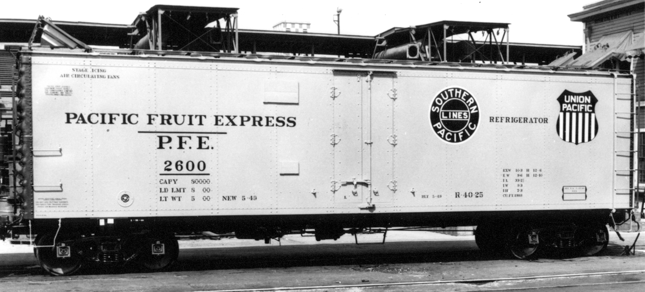
Two more years elapsed before the construction of Class R-40-25 in 1949. Now the placard board remained as in Class R-40-23, but was joined by a smaller board below it. Both boards were now painted orange. The bolster location of a route card board was retained, as can be seen in this view at Los Angeles Shop (PFE photo, author’s collection):
The last class of any size in my pre-1955 discussion was Class R-40-26, built in 1952 and the first class built new with sliding doors. This class had board locations duplicating those of Class R-40-25, including the route card board; all boards were now orange (PFE photo, author’s collection):
It’s worth mentioning, by the way, that all these views are of as-built cars. When a car was shopped in the years after its construction, it normally would have its placard and other boards applied or moved in accord with current practice at that time. Thus older cars in a year like 1953 would mostly have updated board locations. In particular, older cars with paint schemes from later years should definitely have placard board patterns matching the era of the paint scheme.
What about models in HO scale? Without putting too fine a point on it, the simple fact is that few models of steel PFE cars have had a route card board at the bolster (only one I know of is the InterMountain or IM R-40-10 model), and many have lacked or had incorrect placard boards as well.
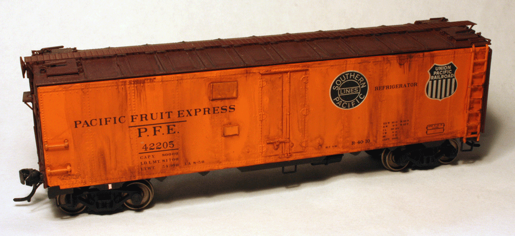
Here is a photo of an IM model of the R-40-10, having black-white heralds and thus also having the post-1949 placard boards (painted orange); the IM versions of R-40-10 representing as-built cars correctly have no placard boards. I have added a route card to the model’s board, located on the side sill at the bolster.
If needed, placard boards are easily added with thin styrene sheet. The prototype placard board was 16 inches high and 24 inches long, often tongue-and-groove construction so without a visible separation of the boards, or in later years sometimes plywood. I have occasionally scribed the board separations but in most prototype photos they are not visible. The smaller boards on reefer car sides varied, but were often about 8 inches square. The same appears true of the route card boards on steel box car doors.
This model shown below is an old Athearn plastic reefer, representing Class R-40-23, which has had some visible upgrades, including a etched-metal Morton running board, wire grabs, and fan shafts; in addition I have added the placard board originally applied to this class, painted black at that time, and a route card board at the bolster.
Correctly locating placard boards and route card boards is part of my effort to model PFE cars as accurately as is reasonable. After all, when placing route cards on models, they should be in the right place on the car!
Tony Thompson
It turns out that PFE changed location of placard boards, though not of route card boards, on almost every class of steel cars in the transition era, that is, up to 1955. (I model 1953.) I will illustrate this point with photos of the various classes (much more information and additional photos are in the book, Pacific Fruit Express (2nd edition), Anthony W. Thompson, Robert J. Church, and Bruce H. Jones, Signature Press, 2000. The photos I am showing here were chosen to show the route card board locations, not as outstanding portraits of the various classes. The book generally has much better images to illustrate the classes.
The first PFE steel ice cars were built in 1936 and 1937, Class R-40-10. As was common for reefers of many owners at the time, these cars had no placard board. Their route card board was on the side sill tab at the left bolster (PFE photo, author’s collection):
As pointed out in the previous post on route cards, many car types had this left-bolster location for route card boards.
The following class, R-40-14, was built in 1941. These cars continued to have their route card boards at the left bolster, as is just visible here (click on the image to enlarge it), but a placard board, painted black, was applied to the right of the car door (R.H. McFarland photo, Arnold Menke collection):
The next class, R-40-20, was built in 1945. Now a smaller board was added to the left of the door, with the placard board still on the right. The route card board was again installed at the left bolster (General American photo, author’s collection):
Only two years later, in 1947, PFE’s largest class of steel cars was built, Class R-40-23, and now the placard board was moved to the left of the car door and a little higher, and the smaller board seen on Class R-40-20 was omitted. And once again, the route card board was applied at the left bolster (Wilbur C. Whittaker photo, author’s collection):
A route card is visible on this car’s board.
Two more years elapsed before the construction of Class R-40-25 in 1949. Now the placard board remained as in Class R-40-23, but was joined by a smaller board below it. Both boards were now painted orange. The bolster location of a route card board was retained, as can be seen in this view at Los Angeles Shop (PFE photo, author’s collection):
The last class of any size in my pre-1955 discussion was Class R-40-26, built in 1952 and the first class built new with sliding doors. This class had board locations duplicating those of Class R-40-25, including the route card board; all boards were now orange (PFE photo, author’s collection):
It’s worth mentioning, by the way, that all these views are of as-built cars. When a car was shopped in the years after its construction, it normally would have its placard and other boards applied or moved in accord with current practice at that time. Thus older cars in a year like 1953 would mostly have updated board locations. In particular, older cars with paint schemes from later years should definitely have placard board patterns matching the era of the paint scheme.
What about models in HO scale? Without putting too fine a point on it, the simple fact is that few models of steel PFE cars have had a route card board at the bolster (only one I know of is the InterMountain or IM R-40-10 model), and many have lacked or had incorrect placard boards as well.
Here is a photo of an IM model of the R-40-10, having black-white heralds and thus also having the post-1949 placard boards (painted orange); the IM versions of R-40-10 representing as-built cars correctly have no placard boards. I have added a route card to the model’s board, located on the side sill at the bolster.
If needed, placard boards are easily added with thin styrene sheet. The prototype placard board was 16 inches high and 24 inches long, often tongue-and-groove construction so without a visible separation of the boards, or in later years sometimes plywood. I have occasionally scribed the board separations but in most prototype photos they are not visible. The smaller boards on reefer car sides varied, but were often about 8 inches square. The same appears true of the route card boards on steel box car doors.
This model shown below is an old Athearn plastic reefer, representing Class R-40-23, which has had some visible upgrades, including a etched-metal Morton running board, wire grabs, and fan shafts; in addition I have added the placard board originally applied to this class, painted black at that time, and a route card board at the bolster.
Correctly locating placard boards and route card boards is part of my effort to model PFE cars as accurately as is reasonable. After all, when placing route cards on models, they should be in the right place on the car!
Tony Thompson
Friday, November 18, 2011
Upgrading old models, Part 4: an update
In a previous post, I described the first part of the work I did to upgrade an old Athearn metal box car in HO scale. The idea was not to claim any special significance to this particular model, but to show the kind of process needed with older models to sustain consistency with modern freight car models and, of course, modeling standards. Here’s a link to that previous post on the model work: http://modelingthesp.blogspot.com/2011/09/upgrading-old-models-4.html .
The Athearn model represents a 1937 AAR standard box car, but as shown in the previous post, was numbered and lettered as an Illinois Central postwar car, which should have had different ends, among other things. So to make the car number consistent with the prewar model car body, it needed to be renumbered. I chose IC 18545 as its new number.
I had used a decal set from Jerry Glow to renumber the car, and corrected its built date to 1940 (consistent with the car number). If you’d like to get one of these sets, it’s the 10'4" IH set for IC; scroll down on Jerry’s web page ( http://home.comcast.net/~jerryglow/decals/full.html ). Then with all model work done, I weathered it. I used my usual acrylic weathering method, which is essentially a wash (see the joint clinic handout prepared by Richard Hendrickson and me for a clinic at the Lisle 2011 meeting, available at: http://modelingthesp.blogspot.com/2011/10/weathering-clinic-handout.html ). Since the car is being modeled as a prewar car, it can be presented as pretty dirty.
Upon completing the weathering coat, I covered the old capacity data and reweigh date with rectangles of boxcar-red decal sheet, included in the Sunshine decal sets for reweigh data, and added fresh capacity numbers, using the ones in the Jerry Glow set. This particular group of Illinois Central box cars had 80,000 pounds capacity, not the 100,000 pounds that is typical of most 1937 AAR box cars, so the Jerry Glow set is essential in providing those data. The set also includes a reweigh symbol of JSTN, for Johnston Yard in South Memphis, a busy place on the IC and a likely candidate for a reweigh symbol.
Here is a snapshot of the completed car, including a few chalk marks made with a Prismacolor white pencil and both placard and route card on the door.
This has been an interesting challenge of a project, and though there are no doubt easier ways to arrive at this final result, I have enjoyed solving the various problems associated with this upgrade. I’m pleased to have this veteran model now suitable for service on my layout.
Tony Thompson
The Athearn model represents a 1937 AAR standard box car, but as shown in the previous post, was numbered and lettered as an Illinois Central postwar car, which should have had different ends, among other things. So to make the car number consistent with the prewar model car body, it needed to be renumbered. I chose IC 18545 as its new number.
I had used a decal set from Jerry Glow to renumber the car, and corrected its built date to 1940 (consistent with the car number). If you’d like to get one of these sets, it’s the 10'4" IH set for IC; scroll down on Jerry’s web page ( http://home.comcast.net/~jerryglow/decals/full.html ). Then with all model work done, I weathered it. I used my usual acrylic weathering method, which is essentially a wash (see the joint clinic handout prepared by Richard Hendrickson and me for a clinic at the Lisle 2011 meeting, available at: http://modelingthesp.blogspot.com/2011/10/weathering-clinic-handout.html ). Since the car is being modeled as a prewar car, it can be presented as pretty dirty.
Upon completing the weathering coat, I covered the old capacity data and reweigh date with rectangles of boxcar-red decal sheet, included in the Sunshine decal sets for reweigh data, and added fresh capacity numbers, using the ones in the Jerry Glow set. This particular group of Illinois Central box cars had 80,000 pounds capacity, not the 100,000 pounds that is typical of most 1937 AAR box cars, so the Jerry Glow set is essential in providing those data. The set also includes a reweigh symbol of JSTN, for Johnston Yard in South Memphis, a busy place on the IC and a likely candidate for a reweigh symbol.
Here is a snapshot of the completed car, including a few chalk marks made with a Prismacolor white pencil and both placard and route card on the door.
This has been an interesting challenge of a project, and though there are no doubt easier ways to arrive at this final result, I have enjoyed solving the various problems associated with this upgrade. I’m pleased to have this veteran model now suitable for service on my layout.
Tony Thompson
Thursday, November 17, 2011
Operations: demand-based car flow-3
There are several ways in which computer techniques can be applied to a waybill system. I’ve already written about the computer applications I use for my waybill preparation. But this post is about computer usage in car flow management. I will just describe a couple of examples, rather than try to be comprehensive.
One issue sometimes raised is the waybill selection process. Simply drawing the next waybill for a particular industry from the front of a stack, and returning used ones to the rear of the stack, strikes some as too much of a fixed sequence. One can of course shuffle the waybill stack from time to time, but there are those to whom the resulting overtones of a card game are bothersome. I experimented with a computer method to select upcoming waybills. Here is how it works.
For a particular industry, say a packing shed, a certain number of waybills has been created, let’s say 22. These are all outbound loads of produce and so are essentially interchangeable. We now want to select one of those 22. In Microsoft Excel, one can set up to do this with random numbers. For this simple example, this is pretty easy to do. Excel contains a random number generator, and if you don’t have an Excel manual or after-market guidebook, there are on-line directions for how to set it up. Here is a link to one example: http://www.mariasguides.com/2007/06/28/random-number-generator-for-excel/ . You can readily Google others.
This method delivers a number, between 1 and 22 in this example, which corresponds to one of the 22 waybills. This of course implies that the waybills are numbered for each industry, and for convenience in use, would need to be filed in numerical order. Then locating bill 17, if that number is selected, is a quick process.
But this example, the 22 waybills for outbound produce loads at a packing shed, is pretty simple. Most industries, including packing sheds, do have other traffic (such as shipping boxes inbound at a packing shed), and so waybill stacks may have to be sorted by car type or by inbound vs. outbound. Those kinds of details are present in the tables I show below, and in fact I have separated inbound and outbound traffic waybills for a couple of my larger industries. That means that the Excel method has to be refined a little further.
To illustrate the coding I used, I show a table from the prior post on waybill scheduling (at: http://modelingthesp.blogspot.com/2011/11/operations-demand-based-car-flow-2.html ). This contains 10 days of inbound car movements for two towns, each having three or four industries and a line for “random” or unusual waybills
The first step is to code the industries and car movements. Here’s what I did. I gave the industries arbitrary numbers (510 series for Shumala, 520 series for Ballard), and for each car requirement, created a two-digit code. The first digit has the values of either zero, one or two, denoting no move, an empty car, or a loaded car. The second digit has values 1 to 9, denoting car types. I won’t list them because they are indicated in a footnote to the following table. Then the exact same table as shown above looks like this:
Though presented as a text table, these are the entries in my Excel file, with each cell shown as presented. With the foregoing descriptions of codes, you can see that this is the same as the table shown above. The one thing that may appear different is that in the upper table, “random” entries are present for a third town, Santa Rosalia (SR), and those are omitted in the Excel table.
I ran a number of experiments with this Excel set-up, and was pleased to find the random-number-generator approach worked fine and did deliver waybill numbers in a satisfying and varied way. But it’s worth mentioning that a relatively random selection of waybills can be accomplished just by grabbing a waybill from somewhere within a filed stack. For limited numbers of waybills, this may be less effort than formally generating random numbers.
I should further emphasize that the Excel technique described above is only a method of randomizing the selection of waybills, not a waybill creation method nor a scheduling method. Waybill creation directly in the computer is being explored by a number of modelers around the U.S. In most cases I’m aware of, they are using Excel. A serious limitation (to my way of thinking) is that the scanned railroad graphics I use at the head of my waybills can’t readily be inserted into Excel waybills. I very much like the effect of the actual railroad graphics and it’s become a feature I especially value about my system.
I know of at least one person who is using the random-number generator in Excel to do scheduling, that is, to identify industry car demand by a random number. To me, this misses the entire purpose of a demand-based car flow approach: to duplicate the regular or periodic patterns in car movement as well as the relatively random ones.
This Excel experiment was only intended to illustrate how a very large layout, with large numbers of waybills and industries, might go about pulling the waybills to fulfill a schedule. On my relatively small layout, I don’t have any difficulty or delay in simply consulting a paper copy of my distribution schedule.
Tony Thompson
One issue sometimes raised is the waybill selection process. Simply drawing the next waybill for a particular industry from the front of a stack, and returning used ones to the rear of the stack, strikes some as too much of a fixed sequence. One can of course shuffle the waybill stack from time to time, but there are those to whom the resulting overtones of a card game are bothersome. I experimented with a computer method to select upcoming waybills. Here is how it works.
For a particular industry, say a packing shed, a certain number of waybills has been created, let’s say 22. These are all outbound loads of produce and so are essentially interchangeable. We now want to select one of those 22. In Microsoft Excel, one can set up to do this with random numbers. For this simple example, this is pretty easy to do. Excel contains a random number generator, and if you don’t have an Excel manual or after-market guidebook, there are on-line directions for how to set it up. Here is a link to one example: http://www.mariasguides.com/2007/06/28/random-number-generator-for-excel/ . You can readily Google others.
This method delivers a number, between 1 and 22 in this example, which corresponds to one of the 22 waybills. This of course implies that the waybills are numbered for each industry, and for convenience in use, would need to be filed in numerical order. Then locating bill 17, if that number is selected, is a quick process.
But this example, the 22 waybills for outbound produce loads at a packing shed, is pretty simple. Most industries, including packing sheds, do have other traffic (such as shipping boxes inbound at a packing shed), and so waybill stacks may have to be sorted by car type or by inbound vs. outbound. Those kinds of details are present in the tables I show below, and in fact I have separated inbound and outbound traffic waybills for a couple of my larger industries. That means that the Excel method has to be refined a little further.
To illustrate the coding I used, I show a table from the prior post on waybill scheduling (at: http://modelingthesp.blogspot.com/2011/11/operations-demand-based-car-flow-2.html ). This contains 10 days of inbound car movements for two towns, each having three or four industries and a line for “random” or unusual waybills
The first step is to code the industries and car movements. Here’s what I did. I gave the industries arbitrary numbers (510 series for Shumala, 520 series for Ballard), and for each car requirement, created a two-digit code. The first digit has the values of either zero, one or two, denoting no move, an empty car, or a loaded car. The second digit has values 1 to 9, denoting car types. I won’t list them because they are indicated in a footnote to the following table. Then the exact same table as shown above looks like this:
I ran a number of experiments with this Excel set-up, and was pleased to find the random-number-generator approach worked fine and did deliver waybill numbers in a satisfying and varied way. But it’s worth mentioning that a relatively random selection of waybills can be accomplished just by grabbing a waybill from somewhere within a filed stack. For limited numbers of waybills, this may be less effort than formally generating random numbers.
I should further emphasize that the Excel technique described above is only a method of randomizing the selection of waybills, not a waybill creation method nor a scheduling method. Waybill creation directly in the computer is being explored by a number of modelers around the U.S. In most cases I’m aware of, they are using Excel. A serious limitation (to my way of thinking) is that the scanned railroad graphics I use at the head of my waybills can’t readily be inserted into Excel waybills. I very much like the effect of the actual railroad graphics and it’s become a feature I especially value about my system.
I know of at least one person who is using the random-number generator in Excel to do scheduling, that is, to identify industry car demand by a random number. To me, this misses the entire purpose of a demand-based car flow approach: to duplicate the regular or periodic patterns in car movement as well as the relatively random ones.
This Excel experiment was only intended to illustrate how a very large layout, with large numbers of waybills and industries, might go about pulling the waybills to fulfill a schedule. On my relatively small layout, I don’t have any difficulty or delay in simply consulting a paper copy of my distribution schedule.
Tony Thompson
Monday, November 14, 2011
Route cards — 3
I have received a very pertinent question via email, namely, where were route cards posted when the board for them isn’t obvious? Particularly for older models, on which these details were often omitted, it might not be very clear where they should go.
When there was a placard board on the car door (on a box car) or next to it (on a steel reefer), the route card board is usually not far away. And on a wood-sheathed car, it was often assumed that car clerks would staple onto the wood somewhere, and no route card board might be provided.
But there are exceptions, which I’ll now describe. First, railroads had the option to locate the route card board wherever they wished, and that choice might not be the usual one. For example, several classes of Union Pacific steel box cars had the usual placard boards on the doors, but located the route card board at the left bolster, as shown in this Wilbur Whittaker photo:
Models of some UP box cars have faithfully omitted the route card board on the car door, but have not provided it at the bolster location, so it needs to be added.
In most cases, these boards were eight inches high and 12 inches long, but sometimes they were different sizes or different proportions. A prototype photo is your best guide.
A second point to recognize is that on open-top cars, it was very common to put a route card board near or at the left bolster location, near the bottom of the car side, as in the UP box car above. But many exceptions can be found. Here is an SP gondola, in an SP photo, which despite its wood sheathing does have a route card board, two side panels to the right of the bolster:
But note that the car clerk has ignored the board and tacked the card near the bolster!
And sometimes SP chose to put the route card board all the way to the right end of the car (shown here in another SP photo). This was done on some classes of SP ballast hoppers too. You may click on either of these photos to enlarge them to see details.
Again, prototype photos are essential to correctly locate route card boards on cars other than house cars, and even on house cars like the UP box car shown above.
On models which don’t have a route card board, or which have one located incorrectly, I just use styrene strip, of scale 1 x 8-inch size, and cut off 12-inch lengths. Of course when a prototype photo shows a route card board of different size or proportion, I try to approximate it by appropriate trimming of the same strip styrene.
I added such a styrene route card board to an Ulrich metal GS gondola model, modified for SP’s Class G-50-12 with two-level Dalman trucks (from Tahoe Model Works). The load in the car is a Chooch product. As you can see, I located the board in accord with the prototype photo shown above.
As is obvious in the photo, I have not chosen to replace the cast-on grab iron representations with wire grabs. That Ulrich white metal is hard stuff!
I will mention in passing that the most common car types to lack route cards in prototype photos are open-top cars, so my recommendation would be to “card” most house cars, but maybe only half or so of your open-top cars: gondolas, hoppers, and flat cars.
Lastly, I should mention a usage seen even on cars which did have route card boards: car clerks just stapled the route cards to any exposed wood on the car, such as the edge of tank car walkway (as long as the walkway was wood), or the edge of a flat car deck. Here’s an SP tank car example, in a George Sisk photo taken at Kansas City in 1959:
When there was a placard board on the car door (on a box car) or next to it (on a steel reefer), the route card board is usually not far away. And on a wood-sheathed car, it was often assumed that car clerks would staple onto the wood somewhere, and no route card board might be provided.
But there are exceptions, which I’ll now describe. First, railroads had the option to locate the route card board wherever they wished, and that choice might not be the usual one. For example, several classes of Union Pacific steel box cars had the usual placard boards on the doors, but located the route card board at the left bolster, as shown in this Wilbur Whittaker photo:
Models of some UP box cars have faithfully omitted the route card board on the car door, but have not provided it at the bolster location, so it needs to be added.
In most cases, these boards were eight inches high and 12 inches long, but sometimes they were different sizes or different proportions. A prototype photo is your best guide.
A second point to recognize is that on open-top cars, it was very common to put a route card board near or at the left bolster location, near the bottom of the car side, as in the UP box car above. But many exceptions can be found. Here is an SP gondola, in an SP photo, which despite its wood sheathing does have a route card board, two side panels to the right of the bolster:
But note that the car clerk has ignored the board and tacked the card near the bolster!
And sometimes SP chose to put the route card board all the way to the right end of the car (shown here in another SP photo). This was done on some classes of SP ballast hoppers too. You may click on either of these photos to enlarge them to see details.
Again, prototype photos are essential to correctly locate route card boards on cars other than house cars, and even on house cars like the UP box car shown above.
On models which don’t have a route card board, or which have one located incorrectly, I just use styrene strip, of scale 1 x 8-inch size, and cut off 12-inch lengths. Of course when a prototype photo shows a route card board of different size or proportion, I try to approximate it by appropriate trimming of the same strip styrene.
I added such a styrene route card board to an Ulrich metal GS gondola model, modified for SP’s Class G-50-12 with two-level Dalman trucks (from Tahoe Model Works). The load in the car is a Chooch product. As you can see, I located the board in accord with the prototype photo shown above.
As is obvious in the photo, I have not chosen to replace the cast-on grab iron representations with wire grabs. That Ulrich white metal is hard stuff!
I will mention in passing that the most common car types to lack route cards in prototype photos are open-top cars, so my recommendation would be to “card” most house cars, but maybe only half or so of your open-top cars: gondolas, hoppers, and flat cars.
Lastly, I should mention a usage seen even on cars which did have route card boards: car clerks just stapled the route cards to any exposed wood on the car, such as the edge of tank car walkway (as long as the walkway was wood), or the edge of a flat car deck. Here’s an SP tank car example, in a George Sisk photo taken at Kansas City in 1959:
Note that the car does have a route card board, just to the right of the ladder, above the walkway, but the clerk ignored it and placed the route card where he thought it would do the most good. Here is my version of it, using a W.A. Drake brass model of the same SP tank car class as the prototype photo (O-50-14):
I used yellow paper for this one.
Route cards add visual interest to freight cars, even though they are quite small, because they are light colors and are eye-catching. And I believe it is interesting to model both standard route card locations (on the board provided), and also the different kinds of route card locations which are not on the boards. If you haven’t applied any route cards yet, give it a try and I think you’ll like the effect.
Tony Thompson
Route cards — 2
The question has arisen as to what route cards looked like. I don’t have any collection of them, but can provide two examples. The general size was mentioned in the prior post on this topic, at: http://modelingthesp.blogspot.com/2011/11/chalk-marks-and-route-cards.html .
Both these examples are from the book by E.W. Coughlin, entitled Freight Car Distribution and Car Handling and in the United States (AAR: 1956), an extremely helpful and informative book for those interested in car movements. For anyone who wants a copy, they have been readily available used on the Internet.
This Missouri Pacific form was printed in triplicate, the bottom copy of which was a manila card to be attached to the route card board on the freight car. Its first two copies were for clerks’ use.
Like many kinds of Empty Car Bills, this can serve for moving foreign empties homeward, or directing cars to locations which needed empty cars.
Coughlin also discussed the use of “switching cards,” which could be applied in a terminal yard to direct cars to local industries, or could be applied to cars being picked up at those industries. The example I’m showing would be to direct a card to a switching “zone,” Zone 300, and to industry 313 in that zone. He doesn’t state the origin of the example, but note that it identifies Portland Terminal on the card.
Again, this is stated as a manila card, but can be any color of card stock which the railroad may have felt achieved a useful color coding. I mentioned in the prior post that careful examination of color photos shows white, yellow, blue and pink examples along with the classic manila color, and light green examples are also known. These are still conventional colors today, for colored paper and card stock, so are readily available at any stationery store.
The ambitious modeler might use switching cards with even bigger numerals than the one shown above, and rely on operating crews to read them--but personally I doubt that’s practical in HO scale with indoor lighting. It might be a practical idea in S or O scales.
So in HO scale, which I model, since I consider any card as small as this to be unreadable, I simply use small blank pieces of colored paper, in the area of 6 scale inches square. Photos show that many route cards were rectangular, so most of mine are that shape.
Tony Thompson
Both these examples are from the book by E.W. Coughlin, entitled Freight Car Distribution and Car Handling and in the United States (AAR: 1956), an extremely helpful and informative book for those interested in car movements. For anyone who wants a copy, they have been readily available used on the Internet.
This Missouri Pacific form was printed in triplicate, the bottom copy of which was a manila card to be attached to the route card board on the freight car. Its first two copies were for clerks’ use.
Like many kinds of Empty Car Bills, this can serve for moving foreign empties homeward, or directing cars to locations which needed empty cars.
Coughlin also discussed the use of “switching cards,” which could be applied in a terminal yard to direct cars to local industries, or could be applied to cars being picked up at those industries. The example I’m showing would be to direct a card to a switching “zone,” Zone 300, and to industry 313 in that zone. He doesn’t state the origin of the example, but note that it identifies Portland Terminal on the card.
Again, this is stated as a manila card, but can be any color of card stock which the railroad may have felt achieved a useful color coding. I mentioned in the prior post that careful examination of color photos shows white, yellow, blue and pink examples along with the classic manila color, and light green examples are also known. These are still conventional colors today, for colored paper and card stock, so are readily available at any stationery store.
The ambitious modeler might use switching cards with even bigger numerals than the one shown above, and rely on operating crews to read them--but personally I doubt that’s practical in HO scale with indoor lighting. It might be a practical idea in S or O scales.
So in HO scale, which I model, since I consider any card as small as this to be unreadable, I simply use small blank pieces of colored paper, in the area of 6 scale inches square. Photos show that many route cards were rectangular, so most of mine are that shape.
Tony Thompson
Friday, November 11, 2011
Chalk marks and route cards
Among the minor details which add to the realistic appearance of freight cars are chalk marks and route cards (and sometimes placards). This topic was touched on in the clinic handout for the joint weathering clinic by Richard Hendrickson and me, and you can read it through this link: http://modelingthesp.blogspot.com/2011/10/weathering-clinic-handout.html
In this post I want to expand on the subject a bit. First, route cards. Many railroads, in at least some of their terminals, used small cards, roughly 4 to 6 inches square or nearly square, to help switchmen correctly route cars. These were tacked or stapled to what was called a route card board on a steel car, or simply to the sheathing on a wood-sheathed car. Prototype photos show that most cars carried these cards, though not all.
Here is a photo of a clerk attaching a route card to the placard board on the car door. This lowered location for door tack boards was adopted in 1954. Just visible at left, behind the clerk’s head, is the actual route card board. The photo was taken by a Cotton Belt company photographer at Pine Bluff, Arkansas.
The clerk is using a “hammer stapler,” which can be swung like a hammer to deliver a staple on impact. The staple sticks out a little, so the route card can be impaled on the staple ends before stapling, as you see here. Note that some older cards remain on both boards.
These cards are easily added to any freight car with small squares or rectangles of paper. The most common color was manila, but color photos do show white, blue, yellow and pink cards in some cases.
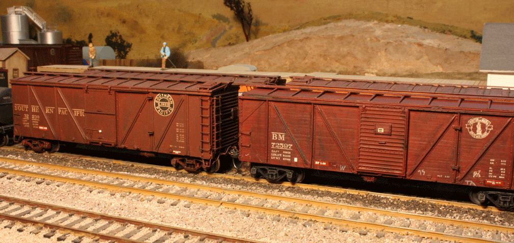
Here are two model freight cars with route cards. The foreground Boston & Maine car also has visible paint patches for reweigh and repack data, as I’ve discussed elsewhere (for example, the corrected version of my article in Railroad Model Craftsman, available here: http://modelingthesp.blogspot.com/2011/03/reweigh-article-from-rmc.html ), and has chalk marks, which I will discuss in a moment.
There is also a placard on the placard board of the box car, high on the car door, which is a decal from a Sunshine decal set for placards. This B&M car is from a Sunshine kit, while the PFE car is from InterMountain.
That same box car can be compared to the box car adjoining it, in this additional view. Here the SP box car has a route card board on the car door, while the B&M car has had a route card applied to its sheathing in a convenient place for the car clerk.
The SP car is a Challenger brass model.
These cards were of course applied to all types of cars, not just house cars. Here is an example for a gondola:
The location, near the lower left corner of the car side, was a common one for route card boards on open-top cars. The gondola is a recent Tangent model.
I have commented in earlier posts on chalk marks. Modelers sometimes call them “graffiti,” but nearly all of them were in fact no such thing. Most were notations applied by car clerks about the track to which the car should be switched, or its outgoing train number, or the industry and car spot to which it was destined, or any of a great number of other bits of information needed by switch crews. The codes varied from yard to yard and railroad to railroad (and likely era to era), and today would be nearly impossible to decode, so simply copying what you see in prototype photos is probably the best way to select these.
Here is a photo of a car clerk, armed with the usual one-inch diameter “railroad chalk,” noting something on a car side. This is a T&NO company photo, taken at the road’s large Englewood yard at Houston, Texas.
In model form, these can be added with Clover House dry transfers, or with any of several Sunshine decal sets (available in white, gray and yellow). They can also be readily added with a colored pencil, with as sharp a point as you can make, in white, gray, or yellow. Most of mine in these photos were done with a pencil. My own preference is for the Prismacolor brand of these pencils, available in any art supply store, as they seem to perform best for me.
Here is another freight car, with reweigh and repack data, as well as a route card, and with added chalk marks. They are a mixture of Clover House transfers and the white pencil technique.
The model is from a Sunshine kit of a C&NW rebuild of that road’s USRA double-sheathed box cars.
The route cards and chalk marks are minor details but I believe they add greatly to the realistic appearance of model freight cars, following what one sees in prototype photos.
Tony Thompson
In this post I want to expand on the subject a bit. First, route cards. Many railroads, in at least some of their terminals, used small cards, roughly 4 to 6 inches square or nearly square, to help switchmen correctly route cars. These were tacked or stapled to what was called a route card board on a steel car, or simply to the sheathing on a wood-sheathed car. Prototype photos show that most cars carried these cards, though not all.
Here is a photo of a clerk attaching a route card to the placard board on the car door. This lowered location for door tack boards was adopted in 1954. Just visible at left, behind the clerk’s head, is the actual route card board. The photo was taken by a Cotton Belt company photographer at Pine Bluff, Arkansas.
The clerk is using a “hammer stapler,” which can be swung like a hammer to deliver a staple on impact. The staple sticks out a little, so the route card can be impaled on the staple ends before stapling, as you see here. Note that some older cards remain on both boards.
These cards are easily added to any freight car with small squares or rectangles of paper. The most common color was manila, but color photos do show white, blue, yellow and pink cards in some cases.
Here are two model freight cars with route cards. The foreground Boston & Maine car also has visible paint patches for reweigh and repack data, as I’ve discussed elsewhere (for example, the corrected version of my article in Railroad Model Craftsman, available here: http://modelingthesp.blogspot.com/2011/03/reweigh-article-from-rmc.html ), and has chalk marks, which I will discuss in a moment.
There is also a placard on the placard board of the box car, high on the car door, which is a decal from a Sunshine decal set for placards. This B&M car is from a Sunshine kit, while the PFE car is from InterMountain.
That same box car can be compared to the box car adjoining it, in this additional view. Here the SP box car has a route card board on the car door, while the B&M car has had a route card applied to its sheathing in a convenient place for the car clerk.
The SP car is a Challenger brass model.
These cards were of course applied to all types of cars, not just house cars. Here is an example for a gondola:
The location, near the lower left corner of the car side, was a common one for route card boards on open-top cars. The gondola is a recent Tangent model.
I have commented in earlier posts on chalk marks. Modelers sometimes call them “graffiti,” but nearly all of them were in fact no such thing. Most were notations applied by car clerks about the track to which the car should be switched, or its outgoing train number, or the industry and car spot to which it was destined, or any of a great number of other bits of information needed by switch crews. The codes varied from yard to yard and railroad to railroad (and likely era to era), and today would be nearly impossible to decode, so simply copying what you see in prototype photos is probably the best way to select these.
Here is a photo of a car clerk, armed with the usual one-inch diameter “railroad chalk,” noting something on a car side. This is a T&NO company photo, taken at the road’s large Englewood yard at Houston, Texas.
In model form, these can be added with Clover House dry transfers, or with any of several Sunshine decal sets (available in white, gray and yellow). They can also be readily added with a colored pencil, with as sharp a point as you can make, in white, gray, or yellow. Most of mine in these photos were done with a pencil. My own preference is for the Prismacolor brand of these pencils, available in any art supply store, as they seem to perform best for me.
Here is another freight car, with reweigh and repack data, as well as a route card, and with added chalk marks. They are a mixture of Clover House transfers and the white pencil technique.
The model is from a Sunshine kit of a C&NW rebuild of that road’s USRA double-sheathed box cars.
The route cards and chalk marks are minor details but I believe they add greatly to the realistic appearance of model freight cars, following what one sees in prototype photos.
Tony Thompson
Subscribe to:
Posts (Atom)