Tuesday, March 29, 2016

Building a Quonset hut machine shop

One of the industries at my layout town of Ballard has been a machine shop, ever since the era when the layout was in Pittsburgh. In the map on my post about the old layout (it’s at this link: http://modelingthesp.blogspot.com/2012/03/survival-from-my-old-layout.html ), this industry was no. 24 on the map, and was called Santa Barbara Tool & Implement (the layout was then set in Santa Barbara County). In the late days of that layout, I changed the name to Santa Barbara Tool & Machine, to get more of a machine shop name. The building used on the Pittsburgh layout was a partly assembled Tru-Scale kit of the late 1940s, which I had purchased along with its original kit box. It was a Quonset hut, 40 by 80 feet in footprint.
     [A little historical background: the Quonset hut was designed by the U.S. Navy in 1940 as a building that could be shipped anywhere in pieces, and assembled quickly by unskilled labor. It was based on, and looks much like, the British Nissen hut of World War I. More than 150,000 Quonset huts were manufactured during World War II, and after the war were sold in large numbers as surplus. The original hut was 16 x 36 feet, but soon additional sizes were made, 20 x 48 feet being one popular size, and ranging up to 40 x 100 feet. All were built with curved sheets of corrugated iron, usually galvanized. The goal was for a team of 10 Seabees to be able to assemble a Quonset in a day; with experience, 6-man teams could erect one in six hours.]
     Below I show the kit box, proclaiming the “all metal” construction of the model, though in fact the interior bulkheads and stringers are pinewood strips, 1/4-inch square.


The construction involved gently bending the corrugated aluminum sheet around something roughly 3 to 4 inches in diameter (a glass milk bottle was recommended, another vanished item in most places), then gluing the sheet to the interior bulkheads and stringers. The kit directions provide a full-size floor plan to aid in assembly, and a perspective cut-away view of the interior bulkheads. (You can click on the image to enlarge it.)


     In the 1950s, there were plenty of Quonset hut structures around the U.S., used for a wide variety of manufacturing and warehousing purposes, so I liked the idea of having one on my layout. I had long intended to complete kit construction, along with maybe upgrading some details, like the rather poor kit windows, but had never done so. Now, with a chance to add this industry to the town of Ballard, I decided to work on the kit. I am now calling this industry “Santa Maria Tool & Machine” since my current layout locale is much nearer Santa Maria than Santa Barbara.
     My first step was to shorten the building. I don’t have space for the full 80-foot length, so decided to cut it down. After all, prototype Quonset huts were built in a range of widths and lengths, and were essentially modular in 4-foot units (the rib spacing). My choice was to retain three side windows instead of the original five, and keep them centered in the side view. This meant a 48-foot length, which is what’s shown in the photo below. The other way to look at the length is that there are about 16 scale feet per side window, and I have cut down from 5 to 3 windows, thus going from 80 scale feet to 48 feet.
     The directions have the comment, “best results with DuPont Cement,” though I don’t know what that was. The adhesive used, DuPont or otherwise, today had pulled away from the joints, and looks a little like ancient Walthers Goo or equivalent. I simply added a generous amount of canopy glue into the joint and re-clamped, using clothes pins (most reversed), This not only stiffens the structure but straightens the somewhat soft aluminum skin.
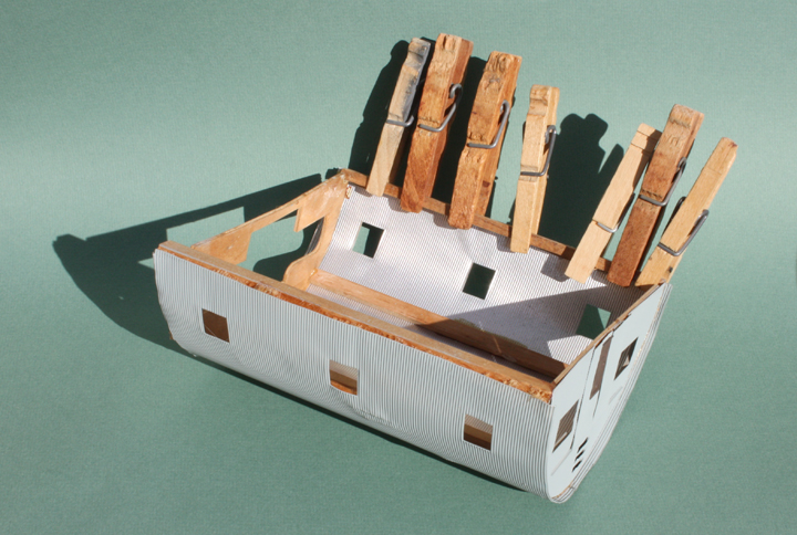

I will continue this process, joint by joint, until the entire structure is solidly glued together.I also have a plan to make simple windows, which don’t have to be too involved because this structure will be located a ways back from the edge of the layout, thus not seen up close.
     [I should mention that today, Tichy and IMEX kits for Quonset huts are out there, though neither has side windows (as civilian versions commonly did) and both are smaller buildings. The Tru-Scale kit does show up for sale on the Internet from time to time, so if you want one of them, patience can be rewarded. There is also a paper model from Clever Models, with a large door let into one side, their kit no. S10.]
     I am pleased to be working on this building, as it has been catching my eye for years and making me want to get into fixing it up. Now it’s under way, and I’ll report on progress in a future post.
Tony Thompson

Saturday, March 26, 2016

A shop track for Shumala

As part of my engine service terminal at Shumala, I built a roundhouse from a Banta Modelworks kit, and added a small machine shop at the rear. This was described in an earlier post (at: http://modelingthesp.blogspot.com/2014/01/shumala-roundhouse-part-3-machine-shop.html ). In the conclusion to my series of posts about building the Banta kit, I showed an overhead view of the new roundhouse in place, with a stand-in shop track simply lying in the approximate correct location (that post is at this link: http://modelingthesp.blogspot.com/2014/02/a-roundhouse-for-shumala-part-5.html ).
     Over time, with the shop track still not spiked down nor powered, I have had to omit from operations any waybills for cars delivered to or picked up from the shop, and so the shop track has remained on the layout “punch list” for all that time. While doing some other electrical work on the layout (as I have described previously at: http://modelingthesp.blogspot.com/2016/03/changing-throttle-connections.html ), I simply gravitated to this additional task, and got the track spiked down, and feeders dropped to power it.
     With the track in place, I added dirt “ballast” to fit with what one sees in SP prototype shots around shops and yards.  This “dirt” is real dirt, screened to a small size. I used my regular method to apply this, mist-wetting the material first with “wet water” (a drop of dishwashing liquid in my spray mister), then using diluted matte medium through an eye dropper to fix it in place. Here is the area with the track completed and ballasted.


     Setting this track also allowed me to plan the space for the coal pile needed alongside the roundhouse, as the boiler room would consume that fuel. (In fact, in the early 1950s, when I model, SP continued to supply coal for many domestic fuel uses, from heating of section houses, cabooses and depots, to cooking in living quarters of depots or section housing, and boilers such as the steam supply for the roundhouse, or for sand house sand dryers.) I mentioned this in a prior blog post about my gondola fleet (see it at: http://modelingthesp.blogspot.com/2011/04/choosing-model-car-fleet-8-gondolas.html ).
     Though photos are not plentiful, it is evident that SP often used a three-sided, open-top storage area for domestic coal, so I decided to do the same. I measured that it could be 4 scale feet deep, so proceeded with that as the critical dimension. I just used Evergreen scribed styrene sheet, with interior corner posts to hold it together, since those posts will be hidden by the coal pile.


     I also decided to add a wheel track. These were commonly seen around roundhouses, and could by located anywhere that was convenient. Workmen could roll the wheelsets, or even complete trucks, on and off the turntable, to move them as needed between a wheel track, roundhouse shop, and the repair track area. The photo below shows two arch-bar trucks being moved by workmen, at the Merchants Despatch shop in East Rochester, New York (detail of photo from Library of Congress, Prints and Photographs Division). You can click to enlarge.


My wheel track then was set up to come off from the turntable, as seen at lower right (the coal storage is not in place in this photo). Tracks like this varied from quite short to car length.

I will have more to say about trucks and wheelsets on this track in a future post.
     Lastly, I added some coal to the coal box and experimented with placement, near the double door leading into the boiler room of the roundhouse, as you see below. I’ve posed a workman with a shovel, and a wheelbarrow, next to the coal box.


Rather than show the coal pile at maximum, it seemed more realistic to show it partly depleted, to reflect ongoing use in the boiler. Also visible at left are stacks of car wheels, and truck sideframes, about which, more later.
     Finishing this side of the roundhouse area, and particularly setting up another switching destination at Shumala, has been fun and will definitely enhance this part of the layout.
Tony Thompson

Wednesday, March 23, 2016

Soundrail 2016

The title here refers to an operating weekend in the Seattle-Tacoma area, known as Soundrail, that is convened in alternate (even-numbered) years. It involves a number of layouts and 60 some participants, from outside the area, many of them invited. This year it was held on March 17–19, and it was the first year I have attended.
     Although there were 24 layouts in all, I operated (as did almost everyone) on only three, and visited a few more on Thursday night’s open houses. The first day I was at Brian Ferris’s HO scale Port Townsend Southern in Olympia. Though not a large layout, I really liked how well done it is, and our crew of eight was busy all day. Many of his scenery features are very nicely accomplished. The photo below shows Glen Presley, with whom I ran a local freight at one point, though in this photo he is switching the yard at Chambers Point. Glen was one of eight Canadians at the event.


     One of the layout visits was to Jim Younkins’ N scale Mud Bay & Southern, which has just exceptional scenery. Jim has taken advantage of the opportunity in N scale to have industries of more realistic size than is practical in larger scales, and many of his model industries were really excellent. I will show one example, his Simpson Door Plant, obviously with plenty of switching and doubtless calling for careful planning to switch efficiently. Quite a layout.


     Bill Sornsin’s large and very ambitious HO Cascade Division (Great Northern) was my second layout for operation, and believe me, it is truly impressive, even in its early state of development. The photo below shows Mark Schutzer operating a local switch job at Holgate Street (Seattle) on the upper deck, with the “south staging” (Portland, etc.) on the lower deck.


     My third layout was Roger Nulton’s Monon Route in S scale. The scenery is truly excellent and the layout ran very smoothly. Shown here are Ray DeBlieck, left, uncoupling a car to set out, and Scott Calvert. The fall foliage is very realistically rendered, unlike so many layouts which just have trees of crimson and fluorescent orange. Anyone who has lived in parts of the country which do have that foliage in the fall can recognize how accurately Roger has modeled it.


I was quite impressed with not only the overall scenic effect, but also with many of the scenic details that Roger has done. I will just show one example, a stock pen with one of those “often seen but seldom modeled” features, the worn spots in the grass leading to the pen. It’s shown below.


     Last, I have to mention one of the most welcoming signs a traveler like me can see, which I photographed on the way to departure at Sea-Tac airport. Turned out the sign was accurate, too, and our travel group took advantage of it to grab a quick dinner.


     This year’s Soundrail was a great experience, and I enjoyed all parts of it. But the main reason I have described what’s involved is to promote the idea of attending one of these events if you can. As the saying goes, if you get the opportunity to attend an operating weekend, run, don’t walk.
Tony Thompson

Sunday, March 20, 2016

Changing throttle connections

From the beginning of controlling my layout with DCC, I chose North Coast Engineering (NCE). My starting system used an NCE Power Cab as the basis. This is a tethered throttle, and more throttles can be added, though the basic power level of 2 to 2.5 amps remains. I later added one additional throttle, and thus have mostly used two throttles, one for each side of the layout. The performance and convenience of this system has been excellent.
     I had placed four plug-in panels on the fascia surface around the layout. Having attached Velcro strips to both the throttle back and to the fascia by each plug-in panel, throttles with their curly-cord connections could be stored by attaching them to the fascia next to any panel. Thus my throttle stations have looked like this:


To the right you can see strings of cars on the staging pull-out table, and in the face of it, the drawer used for storing open-car loads (a project described earlier, at: http://modelingthesp.blogspot.com/2015/04/a-drawer-to-store-open-car-loads.html ).
     Just recently I decided it was time to go wireless. So many layouts on which a person may operate now have radio, that it seemed like time to change. To do this, I replaced my Power Cab foundation with a regular NCE command station and a radio antenna, and then I also needed to convert my throttles from plug-in to radio. This is fairly simple to do, and you can have NCE do the throttle conversion for you. I also decided to divide my layout into two power districts. It is not a particularly big layout, and this division is not needed for power distribution, but it does separate the two districts so that a short in one does not affect the other. I used the NCE EB3 circuit breaker for this.
     Of course, to do this division I had to crawl around under the layout and decipher my existing feeders and terminal strips. I should hasten to say that I do label all feeders underneath the layout, by writing their designation next to them with a Sharpie, right where they emerge under the plywood or whatever the local sub-base is. I also have a long-continuing “layout notebook,” in the form of a three-ring binder, in which I try to record specifics of all new wiring. I showed a page of this notebook in a previous post (see it at: http://modelingthesp.blogspot.com/2012/08/a-modeling-journal.html ), though that post really was primarily about my modeling journal, not the notebook. Here’s another notebook page, with a lot of feeders identified. When things get complex, color coding comes into play.


This kind of information is vital when a job like this one, to rearrange the layout power districts, has to be done, so I’m glad this all these records have been maintained over the years.
     I now have my original throttles converted from plug-in to radio. I appreciate Ray DeBlieck’s help in getting this done. The photo below shows one of the first trains moved with a newly cordless throttle.


     At least for now, the cords and fascia plugs remain in place for when they might be needed, but engineers now can walk wherever they need to go around the layout. Nice change for the better, and I enjoy the freedom as much as visitors will.
Tony Thompson

Thursday, March 17, 2016

My SP pile trestle over Oso Flaco Creek

In a couple of prior posts, I described progress on my creation of Oso Flaco Creek to act in part as a scene divider between my towns of Ballard and Santa Rosalia, as well as a scenic element (the most recent of these posts is at this link: http://modelingthesp.blogspot.com/2015/03/modeling-oso-flaco-creek-part-2.html ). My branch line crosses this creek to reach Santa Rosalia, and I decided the bridge should be an SP pile trestle of standard design. I explained the components of the trestle design in a previous post, and also showed my construction method (you can see it at: http://modelingthesp.blogspot.com/2015/04/building-sp-pile-trestle.html ).
     I combined two steps in installing the pile bents and bulkheads of the trestle, namely to add a thin layer of paper-mache to the bed of the creek, which needs a little texture, at the same time as the trestle was installed. I mixed a water-base paint (a color called “Almond”) into the paper-mache to soften its gray color. This way, the trestle parts were glued down with the paper-mache and were also embedded in it at ground level.
     In the photo below, you can see the two pile bulkheads and the bent of piles at the creek center, and behind the trestle site, the creek disappearing toward the backdrop, as I had begun in the second creek post (cited at the top of this post).


     To keep the trackwork and surrounding ground level, I chose to use a thin styrene sheet to make a track base, with styrene strip along the edges crossing the creek to simulate the beams visible at the edge of this kind of bridge (see my first pile trestle post, cited at the end of the first paragraph above, for a drawing).
     As shown in that first post, I originally planned to use 0.020-inch sheet under the track, and even showed a piece of such sheet in place, but decided to use something thinner still, namely 0.005-inch sheet. This is structurally all right, because the sheet really will only act to hold the ballast on this kind of ballasted-deck trestle. The styrene sheet was set atop the bent caps and was glued in place, and the trackage above it installed.


The sheet being transparent, you can see the support structure beneath, though of course this will disappear when the trestle is ballasted.
     I use a mixture of light gray and dark gray ballast for mainline SP trackage, and with this ballast applied to the track crossing the trestle, it looks like this:


The background track is the lead to the Jupiter Pump and Compressor plant. (If interested, you can read more about my construction of that industry at the following link: http://modelingthesp.blogspot.com/2015/10/jupiter-pump-compressor-part-2.html .)
     From more of a side angle, you can see the piles underneath the transverse caps that support the bridge. Obviously the creek bed and banks remain to be scenicked, but with this bridge complete, I can proceed with those tasks without worrying about exactly where the track is located.


     Completing this bridge has been part of the process of bringing the end of the branch, at Santa Rosalia, into scenic contact with the adjoining scenic area, the town of Ballard. I look forward to more fun developing scenery elements in this area.
Tony Thompson

Monday, March 14, 2016

Another group of Richard Hendrickson open-top car loads

I have posted several descriptions of Richard’s open-top car loads, for example this recent one (see it at: http://modelingthesp.blogspot.com/2015/09/more-richard-hendrickson-open-car-loads.html ). I also posted a set of photos of his interesting and varied lumber loads (that post is at: http://modelingthesp.blogspot.com/2015/06/richard-hendricksons-lumber-loads.html ). In this post, I want to present a few more of his load ideas.
     [For anyone who doesn’t know, or has forgotten, who Richard Hendrickson was, I wrote a post in his memory after he passed away in June 2014, and touched on many of his accomplishments. If you’d like to read it, the post is at this link: http://modelingthesp.blogspot.com/2014/07/in-memoriam-richard-hendrickson.html .]
     Nearly all his loads were glued into or onto the freight cars. This permitted some complex modeling of tie-down details and other arrangements for some flatcar loads. Personally, I forego those details and make nearly all my loads removable, because the car normally will need to move both to and from a destination on the layout. But Richard’s layout plan was really a kind of “railfan” arrangement, with a fairly small diorama having essentially no switching locations on it, supported by a lot of staging. That way, the observer could witness multiple trains passing through the diorama in a single session, and of course the loaded or empty cars would not be switched, but simply roll by. Glued-down loads would not pose any problem.
     Let me now show a few additional examples of his loads. I will start with a signature Santa Fe freight car, the Caswell gondola. Richard modeled it as it was in later years, with the added top chords on the second and seventh side panels. ATSF 172307 was Class GA-7, and is an InterMountain model with added detail and a sand load, glued to a shaped piece of Styrofoam.


I like this load because it shows the smoothed and slightly slumped appearance that I have seen in prototype loads of fine materials like this.
     Richard enjoyed poking fun a coal-country modelers and their needs for massive fleets of hopper cars. “In the West,” he liked to say, “most railroads didn’t move that much coal, and those that did, moved it in gondolas.” He thus left the impression that he had no interest in, nor need for modeling hoppers. But being a serious freight car modeler in spite of those comments, he did build a number of models of hopper cars with coal loads. This car, MP 56037, has had wire grab irons added and other details modified from the Athearn quad hopper.


     A traditional bulk load in model railroading is the scrap load, and the variety of scrap visible in such carloads can make it a very interesting load. Often modelers represent a car as entirely full of scrap, but in fact partial loads were and are common also. Here is one of Richard’s scrap loads, PRR 860017, a Class GS gondola. I believe this was built from a Westerfield kit.


     In addition to bulk loads like these, he did a number of loads of steel pipe, a common sight in transition-era prototype photos. I showed one of them in the first post cited at the top of the present post. Here is another, one of the cars described in Richard Hendrickson’s by-now-classic articles on modeling various mill gondolas by kitbashing the Athearn gondola. This was a two-part series in Prototype Modeler, in the September-October and November-December issues of 1982, pages 31 and 12, respectively. The car is EJ&E 32386.


I was intrigued by that article, “back in the day” when we had few prototypical gondola models available, and I went ahead with a couple of the projects described in those articles (you can see my own version of the EJ&E car in an earlier post, which is at: http://modelingthesp.blogspot.com/2011/12/route-cards-5.html ).
     Finally, I should mention that Richard also modeled numerous open-top cars which were empty. This may not sound interesting, except that he endeavored to depict the kinds of scrap, dunnage remains, cables, steel straps, stakes, broken braces, and other materials that often remained on unloaded flat and gondola cars. Here is one example, ATSF 97198, Class FT-M, an Athearn flat car lengthened to the prototype 44-foot size. The vertical-staff brake wheel isn’t obvious in this view, but it is just visible at lower right. (As with all these photos, you can click to enlarge.)


     As I have spent time with the photos I took of Richard’s freight car models prior to dispersing them to many of his friends and colleagues, I continue to enjoy seeing the thought that went into them. These cars illustrate the depth of modeling which extends beyond mere multiplication of detail, to realistic representation of prototype cars.
Tony Thompson

Friday, March 11, 2016

First 2016 operating session

I scheduled an operating session for the just-past weekend of March 5 and 6, to bring into use several additions to the layout, to further exercise some changes in my waybill system, and of course to have some fun in the process. As usual, there were two two-person crews scheduled each day, to implement the work pattern that seems to work well on this small layout.
     Both sessions went well in terms of realizing what had been planned, though there were some stubborn turnouts that were often dead spots. I will have to redouble my efforts to fix a couple of these. But the car cycles and amounts of switching work seemed to work properly. I am always fascinated at these sessions, in my role as “source of additional information” while watching crews work, how many different ways a town can be switched. There were a couple of unusual techniques this time, too.
     The most noteworthy, I guess, was when Larry Altbaum, working at Shumala, asked me, “Does your turntable work?” This seemed an odd question, as access to the fuel and water columns, or the roundhouse, was not intended to be in the plan. But I answered, “Sure,” and went to see what was going on. Turned out he and his fellow crew member, Lisa Gorrell, had decided to do a car run-around by using the turntable, instead of the fairly long track provided for the purpose. Here they both are, with big grins of, I suppose, triumph. You can see the switcher retrieving its car in the middle distance, alongside the yard office. (You can click to enlarge.)


As visible in the foreground, they had indeed kind of filled up the siding with cars, making the usual run-around (siding-plus-main) less attractive to sort out a single car.
     There was, naturally, equally much activity on the Ballard side of the layout, where the photo below shows the crew of John Sutkus (left) and Jeff Aley hard at work. Jeff was conductor and is deciphering waybills to see what task is next. Jeff is himself knowledgeable and experienced in waybill design, so I enjoyed letting him have a chance to switch with my versions.


     One of the new wrinkles I added to this pair of sessions was operation of express reefers, in accord with the ideas I described earlier about seasonality of produce shipments (see it at: http://modelingthesp.blogspot.com/2016/02/operations-seasonal-traffic.html ). It being March, the early strawberries are just coming into harvest in central California, so Guadalupe Fruit in Ballard is shipping them. Here is the mainline extra train, arriving with an REX express reefer to set out at Shumala (and with a loaded one to pick up), trailed by a mail storage car (see my description of the model project at: http://modelingthesp.blogspot.com/2014/08/modeling-sp-head-end-cars-part-7b.html ) and a 60-foot baggage car. Power is Class P-4 Pacific no. 2402 (a Westside model).


     Another crew on the weekend is shown below, working at Shumala, Dave Falkenburg at left and David Parks to the right. Falkenburg is the conductor here, and evidently is “having a think” about the waybills, which he has tilted up against each car. Engineer Parks waits patiently for direction. David is holding a tethered or plugged-in throttle, but one upgrade I’m looking forward to is the conversion to radio throttles. One of these days.


     The next time I put on sessions like these, I hope to have still more changes and improvements to the plan for each session, while continuing to refine and balance work loads for each crew in each location. The balance isn’t bad now, but can always be better. And of course all the waybills will cycle, so there will be in a sense a whole new scenario for the freight cars and trains. Looking forward to it!
Tony Thompson