Sunday, March 31, 2024

Three-compartment tank cars

I recently had an interesting question sent to me by email. The essence of the question was, “Is it realistic to operate three-compartment tank cars?” I did send the questioner a link to Richard Hendrickson’s article in Model Railroad Hobbyist on the topic (“Multiple-compartment tank cars” in Model Railroad Hobbyist, in the issue of February 2015). But it occurred to me that I could add some comments here.

Multiple-compartment tank cars of any kind were relatively rare; by one estimate about 95 percent of all tank cars in the transition era were single-compartment cars. Nevertheless, tank cars with two or more compartments did exist and were often photographed. In HO scale, the most familiar model of such a car is the old Athearn “Blue Box” three-compartment plastic model.

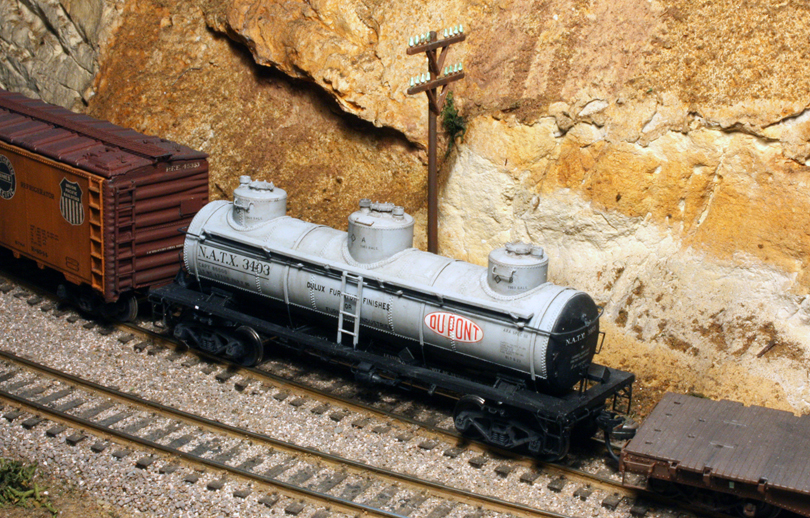
I show an example below. Note that the car has low-height expansion domes with single safety valves, correct for the car as shown, and has the double rivet rows between domes that represent the attachment of the internal bulkheads that separate the compartments. It even has three outlet pipes, one beneath each dome. 

Problem is, no one has ever found a prototype three-compartment car this big, though this may well be what one would look like, if one existed. (Typical prototype three-compartment cars were usually much smaller, and had taller and narrower domes, by the way.)

This is an interesting model, with a discernible history. I have previously talked about the 1950s Athearn and Globe metal tank car kits (see that post at: https://modelingthesp.blogspot.com/2017/10/some-old-metal-tank-car-kits.html ), and it’s long been evident that when Athearn chose to create a new plastic tank car, they began with the three-compartment car shown above. Yet they once had a very nice metal tank car kit for a three-compartment car (shown in the post just cited).

As noted above, prototype three-compartment cars were considerably smaller than the Athearn model shown, often about 6000 gallons total capacity, half the volume of the model shown above. For background on real cars, I recommend John Riddell’s article in Mainline Modeler entitled “ACF Tank Car” (issue for September 1995, pages 42–47). Beyond that introduction, a much fuller account was is the Richard Hendrickson article published in Model Railroad Hobbyist, February 2015.

What occasioned Richard’s article was the release of the beautiful Tangent model of a 6000-gallon three-compartment tank car in HO scale. Here is Richard’s version of this model, lettered with Black Cat decals and with added placards, chalk marks, rust stains at tank bands, and spillage from the domes.

An even better model of a car like this was the Southern Car & Foundry resin kit, modeling a car built by Standard Tank Car Company (a model developed with Richard’s input on the prototype). Moreover, it models a car which later in life, had two new end compartments added, making three altogether (and the new domes are smaller, since they serve smaller compartments than the original single compartment). Here is one of these models built up, lettered to match a prototype photo.
As this SC&F model reminds us, many three-compartment cars came into being as modified single-compartment cars. I have accomplished the same for one of the common uses of such cars, wine transportation. (For much more about tank cars and the wine business, see my “Getting Real” column in the Model Railroad Hobbyist issue for May 2023.) Here is an example, shown spotted for loading at the winery in my layout town of Ballard:

This model began as a Proto2000 insulated tank car, and I added the two end domes, deliberately in a quite different style, consistent with many prototype wine cars. I described the modeling in that MRH article, and also in a prior blog post (see it at: http://modelingthesp.blogspot.com/2017/05/creating-wine-tank-car-part-2.html ).

My recommendation to modelers over the years has always been put those Athearn plastic three-dome cars in a storage box somewhere, to ensure no one sees them on your layout, and if you’re at all meticulous about freight cars, do the same with the Athearn plastic single-dome cars, with their hold-over low dome from the 3-dome model. 

It’s a shame to have to say that, because the Athearn plastic single-dome car is a very accurate Southern Pacific 12,500-gallon tank car — except for that very obvious wrong dome, and a few lesser details. I have for years converted them, a full dozen cars by now, with dome correction and fixing all the other details. A pretty full description of how that is done is here: https://modelingthesp.blogspot.com/2011/05/modeling-sp-tank-cars.html .

But in summary, yes, three-compartment tank cars are entirely prototypical (if fairly rare), they just aren’t much like that old Athearn monster.

Tony Thompson 

Thursday, March 28, 2024

Trackwork wars, Part 10

In a recent post, number 9 in my series on this topic, I showed the work done in leveling some track in the area between my layout towns of Ballard and Santa Rosalia (you can read that post at this link: https://modelingthesp.blogspot.com/2024/02/trackwork-wars-part-9.html ). 

But even as that work was being completed, I realized it was not all of the problem. There remains some variability in the track gauge that still can cause derailments, and in a few places the track gauge becomes too tight. Thus this post.

For example, I have used the clear plastic “test car” shown in the previous post (see first paragraph for link), and even with the track leveled, there are still derailment problems. Below you can just see the leading wheel lifting and turning to derail.

Both these switches have given trouble for some time. The one at left in the photo below is a Peco, and like other Peco switches I have, it has evidently experienced shrinkage in its plastic parts, and the track gauge is now too tight. I corrected this once before, by filing the inside of the rail head. By now I’m not too enthused about continuing with that, as I have had to do the same with two other Peco switches on the layout, and it’s an apparently endless task. At least the other two don’t cause derailments after their gauge is corrected.

[By the way, I contacted the Peco “help” service about this shrinkage. Amazing how naive I was, even at my age: I thought they might apologize for the defect, might even send me a replacement. But in fact, Peco replied that they “had never heard of anyone experiencing shrinkage in a Peco switch,” though I have three different Pecos that have done this, and others around the U.S. have told me the same. Makes me take a deep breath before purchasing more Peco switches.]

Next I began to measure the individual rails in the two switches, since some appeared to perhaps be bent. I soon found that indeed there were bent rails, bent vertically, not horizontally, which is less convenient to fix (perhaps the result of an earlier derailment). At first I began to try and straighten them, which wasn’t going well, when it came to me: “What am I doing? Replace the bloody things!”

My first step, in which I admit I took pleasure, was to remove the annoying Peco switch. Once it was separated from the other track, I felt better already.

Over at the right edge, you can see the existing curved switch, and just above it, a new switch, one I had in stock, but not one that would fit.

I spent some time shopping for new switches, and reading a couple of email lists for comments about the various switches on the market. For the curved turnout at the right of these photos of the area (see middle photo, above), it looked like the dimensions of the relatively new Walthers line of “DCC friendly” switches would fit. 

For the other switch, a left-hand #6, I am still looking at options. The Walthers switch of this kind has a very straight diverging route beyond the frog, which I don’t think will work in my location. There are a couple of other manufacturers of switches that are options.

It would have been nice if these new switches could be located with throw bars exactly where their predecessors were located. But I realize that isn’t likely, so probably the entire switch machine locations (see photo above) will have to be moved, including digging up the buried tubes that carry the activating wires. That’s just to be expected as part of the project.

Now I just need to get the new switches in house and start restoration. Progress reports later.

Tony Thompson

Monday, March 25, 2024

SoundRail 2024

In alternate years, the layout owners around Puget Sound, Washington put together an operating weekend called, for obvious reasons, SoundRail. I attended this years, as I have done four previous SoundRails. I’ve always liked their emblem, combining rail with the waters of the Sound and Seattle’s iconic “Space Needle,” dating from the 1962 World's Fair.

This year, my layout assignments began with Joe Greene, located way up in Sequim, on the upper edge of the Olympic Peninsula. This is a wonderful layout, modeling the C&O in Appalachia in 1974. The job I drew this time was the excellent paper mill model, with (I think) 16 different car spots around the plant. This was interesting and fun! Mark Schutzer and I had a great time switching the entire area, along with some yard work.

The following day, we began the regular schedule of the meet (Joe’s layout was a “bonus” session). My first layout was Dale Kreutzer’s superb Rio Grande Southern 2nd District, set in 1926. I had operated there once before, so knew what to expect. It’s a marvelous job of scenery, the trains ran perfectly, and it was really a pleasure. I had the Mancos Turn, a switching-intensive assignment that was excellent for me, and much of the enjoyment was the beautiful setting.

Next came Bill Sornsin’s Great Northern, modeling the Seattle area and the eastward climb to the top of the Cascades in 1956 in HO scale. I was really looking forward to this, as I had not operated at Bill’s at the previous SoundRail, and was eager to see layout progress. There was a lot! He now has a magnificent model of King Street station, an iconic structure and of course the centerpiece of extensive passenger operation.

I got to work at Interbay Yard, which had only limited operating capability last time I was there, but now was a fully functioning yard, closely following the prototype trackage. The yard crew really had fun all day here. And the prototype yard is still there today, not far from Bill’s home.

My final layout was Jim Younkins’ N-scale Mud Bay & Southern, set in the Olympia area in 1974. This is a huge layout, with very nice scenery and excellent structures. One of the things I like about N scale is that industries can be big enough to look like they really need multiple freight car spots. My job this time (my third visit!) was at Elma, a location with a lot of switching. Here’s a view of North Elma, with the yard area in the foreground.

One of the many nice features of Jim’s layout for visitors is the excellent town maps on the fascia in each area. Here is the map for the scene shown above. (You can click on the image to enlarge it if you wish.)

This was another outstanding SoundRail, a meet I have enjoyed every time I have attended, and I’m sure I will go back. I report all this mostly to show how much interesting fun you can have at a meet like this, and I hope anyone reading this, who hasn’t every operated at such a meet, will seek one out and give it a try.

Tony Thompson

Friday, March 22, 2024

More about Chrysler trucks

In a recent post about the steel express refrigerator conversions of Pacific Fruit Express, I mentioned the Chrysler freight trucks applied to 25 of the cars when they were converted to passenger express service. These were visually distinctive because of the use of an external hydraulic snubber, which projected upwards on the side frame. (You can read that post at: https://modelingthesp.blogspot.com/2024/02/the-steel-express-cars-of-pfe.html .) Here is a photo of the prototype truck (PFE photo, CSRM).

I mentioned in that post that I had made representations of Chrysler trucks for my own car fleet’s PFE steel express reefers, using a casting from Ross Dando’s Twin Star Cars company. This was a nice part and certainly an accurate representation of what you see above. Here is that truck on my PFE car:

I don’t know whether Twin Star Cars will necessarily return that part to inventory. But there is an alternative and perhaps better option today: a company called “Plate C Model Prototypes” has made a 3-D printed version of this truck, now marketing it through 3D Central. You can see the 3D Central trucks at this link: https://3dcentraltrains.com/search?type=product%2Cpage%2Carticle&options%5Bprefix%5D=last&q=trucks . The Chrysler trucks are on page 2, and I used Part 4103-01, the original truck design. As of this writing, they are in stock. (The site warns that things can go in and out of stock, so patience might be necessary).

They really are nicely done. I show a rather close-up photo below, and in my opinion, this compares favorably with the Twin Star Cars version or the prototype photo above. Note in the lower view how much the snubber projects, as should be the case.

But if I already had a nice version of these trucks under my PFE express reefer, why did I buy another pair? Three years ago, I posted about the work I did, modeling one of the General American-Evans pioneer DF box cars, where DF = Damage-Free loaders. (That post can be found here: https://modelingthesp.blogspot.com/2021/02/gaex-box-cars-part-2-modeling.html .) 

The just-linked post has more details, but briefly, the consortium of General American, the car builder, and Evans Products Co., the DF-loader maker, built 540 cars, 340 of them with conventional vertical panels, 8 on each side of the door. The photo below shows an example (George Sisk photo, Charles Winters collection), drawn from the 110 cars built in the late fall of 1950 and leased to the Pennsylvania Railroad.

The prototype GAEX cars had Chrysler trucks (visible above), which originally I decided to ignore, and simply used conventional trucks under the model. But in that post, I prophetically wrote, “Maybe I’ll come back later and redo the trucks.” That’s the reason for buying another pair: so I can complete my GAEX box car.

I won’t go into the model itself, as the background and modeling was adequately described in the two original posts (the second is linked two paragraphs above). For the current topic, what’s important is that now I can “finish” that model with correct trucks. Here are the Plate C trucks installed:

I am glad to make this model more accurate with the replacement of its kit trucks with these impressive 3-D printed versions of the Chrysler freight truck. This is yet another example of the accomplishments of 3-D printing in our hobby.

Tony Thompson

Tuesday, March 19, 2024

Understanding bridges, Part 2

In the previous post, I discussed the most fundamental principle of bridge design, the importance of beam or bridge depth, relative to length. The key point is that the stiffness of a beam (or bridge) depends on the width to the first power, but the depth to the third power. You can read that post at this link: https://modelingthesp.blogspot.com/2024/03/understanding-bridges.html .

Probably the most familiar type of large railroad bridge is the truss bridge. This is really just a beam bridge, but with unnecessary material removed, leaving just the material that ensures the depth of the “beam” (or bridge) is maintained, i.e. keeps the top and bottom apart. The familiar framework of a truss bridge can be understood in that way. I will show a typical railroad bridge, then delve into explanation.

Below you see Southern Pacific’s bridge across the Salinas River at Nacimiento, on the Coast Route, being crossed by a freight behind a pair of rebuilt GP9Es, in 1974 (Ed Workman photo). This is a Pratt truss, as I discuss below.

In the sketches below, imagine that the components shown are a stiff rubber. I think you can readily see in (a) that the bottom has to get longer (tension) and the top will get shorter in response to a load on the top. 

In (b) I show the simplest possible truss, known as a king truss, simply a triangle, and imagine that you have a handle underneath that you can pull down on. Again, I think it’s clear that the two upper members will be squeezed together as the lowest member lengthens. The problem with such a design is that the span is fairly long. Adding a rod between top and bottom (c) would minimize flex of the bottom member and in effect, hangs a floor beam from the top of the truss.

These are the fundamental ideas of how truss members behave. If we now draw a truss that can span a larger gap (it happens to be a Pratt truss; more on that in a moment), I can indicate the names of the truss members (posts, ties, chords, etc.) and you can see the stresses for uniform loading, in effect, equal loads on each floor beam.

Note that I have drawn some members (the top chord and end posts) heavier than the remaining members. This is because they are in compression, while all the other members are in tension and can be lighter. This is one of the attractions of the Pratt truss.

Over the decades, especially in the 19th century, there were a great many truss designs invented, many of them with numerous redundant members (as we now recognize). But quite a few are reasonably efficient designs and have been used for railroad bridges. I show a dozen of them below (a figure from Mallery’s book, citation in the first post of the series). Some, like the Pratt and Warren, are used today. The Howe truss, a carry-over from wooden bridge design, is less efficient as it has numerous members in compression, which have to be heavier.

Finally, one more important bridge type is the arch bridge. This bridge design directly reflects the fact that forces in the bridge are carried in the curvature of the arch, and thus are exerted entirely through the ends of the arch. The best arch bridge, then, is a a full half-circle, and the forces are directed exactly downward. But partially circular arches are also feasible, if sufficiently strong areas at the side of the bridge exist, so that the arch can bear into those sides.

This is not a new idea. Arches were used in ancient times, perhaps most impressively by the Romans. The famous aqueduct near Avignon, France, the Pont du Gard, still stands (photo from USGS website). This was part of a 31-mile aqueduct, and the engineering skill involved is evident because there was only a 56-foot drop over the whole 31 miles of the system.

Modern arch bridges for railroad use, thought not the most common type, certainly do exist. Among the most famous is the Great Northern’s bridge across the Mississippi River at Minneapolis, built in 1883 and carrying rail traffic into the 1980s, but now a hiking trail. In this view (Burlington Northern photo) GN No. 12, the Red River, is leaving Minneapolis for St. Paul behind an E7 diesel.

However, the drawback to the arch bridge is that it is normally erected over falsework which temporarily has to fill the space beneath it, at least if it is a masonry arch. The carton below shows an unlikely alternative (originally published int the Saturday Evening Post, now found throughout the internet):

My purpose in collecting this information and illustrations is to help modelers understand what they are doing when they choose a type of bridge for a layout situation. Mallery’s book contain a great deal more detail on this topic than is practical to show here, but this should suffice as an introduction. And the article by Larry Kline and me, also cited in the first post, contains more information on the history of railroad bridges.

Tony Thompson

Saturday, March 16, 2024

Repainting a GS-4 tender

I have an all-black Broadway Limited HO scale model of a Southern Pacific 4-8-4 locomotive, Class GS-4. That is how these engines were painted once the red and orange Daylight paint scheme began to be removed in the early 1950s. But as I received it, the model is lettered in the pre-1946 lettering scheme, with the road name as “Southern Pacific Lines” in relatively small lettering (9 inches tall) and with a small, lower number on the back of the tender. 

Here is a view of one such prototype GS-4 locomotive, taken at Glendale on November 24, 1943. Locomotive 4431 is at the head end of No. 71, the “Coast Mail” and has been repainted black under wartime conditions (Fred A. Stindt photo, courtesy Bob Church). It’s interesting that the tender lettering is located high on the car side, where it had been in the Daylight scheme.

There are not many good photos of the backs of tenders, but the nearly identical SP tender class applied to the GS-6 locomotives were well photographed  by Guy L. Dunscomb at Oakland in March of 1947 (Arnold Menke collection). The small road number beneath the back-up light is evident.

The Broadway Limited model has these characteristics, as you can see below. But for my operating year of 1953, I definitely have to re-letter the tender. Few SP locomotives retained the pre-1946 lettering past the summer of 1947. The problem now is to research what new lettering to apply.

As I think most SP enthusiasts know, in 1946 SP replaced the scheme just shown with a dramatic increase in size of tender lettering (to 20 inches in height) and discontinued the word “Lines.” Details of the 1946 paint and lettering are contained in the Southern Pacific Painting and Lettering Guide, “Locomotives and Passenger Cars,” revised edition (J.A. Cauthen and J.R. Signor, SPH&TS, Upland, CA, 2019). Views of post-1946 locomotives in black paint are numerous, usually including tenders, as shown below (Bob Church collection).

Tender end numbers were enlarged also, and relocated above the back-up light. But it’s surprisingly hard to find an end photo of a black GS-4 tender in post-1946 lettering. Even Arnold Menke’s outstanding chapter on tenders in Bob Church’s Daylight engine book doesn’t have one (Robert J. Church, Southern Pacific Daylight Locomotives, Signature Press, Berkeley and Wilton, CA, 2004). 

But one of my favorite Don Sims photos does capture exactly that. Here we see GS-4 4448 at Bakersfield, just cut off from the San Joaquin Daylight after its run eastward down the valley. A set of F7 freight diesels will take the train over the Tehachapi. The end lettering is very clear.

This is how I will be re-lettering my GS-4 tender, as I will show in a future post.

Tony Thompson

Wednesday, March 13, 2024

REA express reefers, Part 2

In the first post on this topic, I briefly summarized the history of the Railway Express Agency or REA, and showed examples of some of the cars in their fleet, emphasizing the era that I model, 1953. I also showed a table of the REA pool participants, including Pacific Fruit Express. You can view that post at this link: https://modelingthesp.blogspot.com/2024/03/express-reefers-from-rea.html .

I now want to turn to models of some of these cars, and a description of how I are use these cars in operating my layout. When the layout is operated, the calendar day involved, say May 15, is treated as that day in 1953, and appropriate crops for that day are moved from the six packing houses on the layout whether or not express cars are involved. The most prominent use of those cars is late winter and early spring, when the California strawberry crop first comes in, but these cars also come into use with the first harvest of any previously unavailable crop.

So when a visitor sees a steel car, REX 6220 (an Atlas model), alongside the Guadalupe Fruit Company loading dock in my layout town of Ballard, they can be sure some new crop is being shipped. This car is from the 1947–48 order of 500 cars, REX 6100–6599. In the previous post (see link in first paragraph, above), there is a photo of a prototype car, REX 6164, from this group.

Likewise, seeing an REX car at the icing dock in my town of Ballard, signifies the same thing about crops. as with REX 1227 in the photo below (a Walthers model), though since Guadalupe Fruit has no pre-cooling capability, this car might be receiving a pre-icing, to fill the ice bunkers prior to loading, or an initial icing, filling the bunkers to the top on a departing loaded car.

But of course, looking at the table of the REA pool in the preceding post (see link in first paragraph, above), express reefers of other ownership are certainly possible, particularly PFE express cars. I’ve described those cars in a previous post (see it at:  https://modelingthesp.blogspot.com/2024/01/pfe-express-refrigerators.html ). 

Another prominent member of the REA pool was Great Northern, actually contributing more cars to the REA pool in 1953 than PFE. As it happens, I have an ancient Ambroid kit-built version of a GN wood-sheathed car. Here it’s shown being readied for pickup by a passenger extra on my layout at Shumala.

And of course there might also be express cars of any other railroad, whether or not in the REA pool list, including New York Central. I inherited a nice NYC express reefer, NYC 5943, from Richard Hendrickson (brass, New Jersey International), as you see here, with its distinctive deep side sills. In 1953, NYC had 272 of its original 275 cars like this still in service, numbered NYC 5800–6074.

Although I don’t often load express reefers at the packing houses on my layout, except at those short stretches of harvest season(s) for which they are appropriate, they do show up in mainline passenger trains. Among other things, they carried dairy products and fresh flowers along SP’s Coast Route throughout much of the calendar year. So though PFE is the likeliest reporting mark to show up on an express reefer on my layout, REA and other express cars certainly show up too.

Tony Thompson