In previous posts, I introduced the topic of turnouts (or set-outs or set-offs) for track cars such as speeders. I showed the Southern Pacific Common Standard (CS) drawings for these, and indicated a little about how they were used (see that first post at: https://modelingthesp.blogspot.com/2018/12/track-car-turnouts.html ). I followed that with an introduction to modeling these turnouts (as SP called them), showing how I made up the basic panel of the turnout (that post is here: https://modelingthesp.blogspot.com/2019/01/track-car-turnouts-part-2-modeling.html ).
For my mainline track, with higher rail and placed on more of an embankment, the turnout base using full-profile ties would work fine (I showed that design in the previous post, just cited). But for my branchline track at Santa Rosalia on my layout, the Code 70 rail is close to ground level. For that, I decided to model the ties making up the turnout as just their tops, so I used scale 3 x 8-inch stripwood on the styrene panel. The “low-profile” version is at right in this photo.
These will be painted a weathered brown before installing (more on color later in this post).
Next I needed to prepare the sites for these turnout panels. For the
mainline examples, it was not too critical. I simply scraped away
ballast right next to tie ends, using a chisel blade in a hobby knife,
as you see here at photo center.
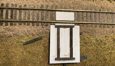
The next step before installation was to decide how to manage the planks between the rails, put there to assist crews in turning track cars from the rails to the turnout. In the prototype, these are situated right below the rail head (see drawing CS 551 in my first post, cited at the top of the present post), but for modeling, we want the height to be clearly below rail height. This is both to make track cleaning easy, and to avoid fouling any low parts of passing rolling stock models. I suppose each modeler would need to examine how this will work on a particular track area.
My own choice was to use Evergreen V-groove styrene sheet. Yes, the grooves exaggerate the joints between adjoining pieces, but I wanted it to be evident that these were separate planks in the installation. After some experimentation, I chose the 0.040-inch thick sheet with 0.100-inch spacing, Evergreen no. 4100. This spacing is 8.7 inches in HO scale, certainly similar to the 9-inch width of prototype ties.
These between-rails set-off timbers are shown in CS 551 as 8 feet long. They have a 2:1 taper on the ends, that is, the taper is twice as long as it is high (identified in CS 551 as “detail of bevel”). I filed such a bevel, then re-scribed the styrene so that the divisions between planks were maintained. I then painted them the same dark brown as the other ties.
Lastly, CS 551 shows that one additional tie was installed on the outside of the rail. This tie also was beveled, according to CS 551. I tried setting all these components in place to see how they appeared. The various full-size ties you see around the panel were used to approximately level the panel. But note, incidentally, that CS 551 says the turnout should be sloped away from the track by a small amount.
To appreciate what one of these track car turnouts might look like after some years in service, the photo below is helpful. It was taken by John Signor near Tunnel 14 on Siskiyou Pass, near Oregon’s southern border, in June 1978. Ignore the locomotives of this westward train and look at the lower left corner.
The color is brown, but fading to a combination of grayed wood and the light dirt color of the surroundings. This is my goal.
I will return to completing this group of track car turnouts in a future post.
Tony Thompson


No comments:
Post a Comment