Way back in July 1987, I had a short article in Railroad Model Craftsman, which happened to receive the Dremel Kitbashing Award for that month. The article described how I had kitbashed a distinctive Pacific Fruit Express car, from Class, R-70-2, which was 52 feet long. I was lucky enough that one of my photos of the completed model was selected for the cover of that issue, as you see below.
I’ll begin with the car itself. I will only briefly describe the kitbash, as it was straightforward. I took two Athearn wood-side reefer kits, cut out the middle of one and used the ends of the other, to make up a long enough car body. Of course the doors had to end up in the center of the new body. I did the same with the two kit roofs, again keeping the Athearn interlocking piece above the door in the center. I didn’t replace the Athearn ends, which are wrong for a 1932-built car, partly because at that time there was no very good replacement Dreadnaught end.
The prototype car had a relatively deep fishbelly underframe, which I created out of 0.020-inch styrene sheet, with cap strips of scale 2 x 4-inch styrene. I chose to re-use the Athearn truck bolsters and coupler boxes, as you see below. Obviously at this point I already painted and lettered the model.
You may also note here that I have narrowed the Athearn side sill by about 50 percent.
Next I added the cross-ties and Cal-Scale AB brakes. This PFE class was built with K brakes, but most of the cars were upgraded in the 1940s to AB brakes. The brass wire piping isn’t visible in this view, though you can see part of the brake rodding at right.
That brake update stimulated me to think about the fact that when PFE did significant shop work on cars in the 1940s, ordinarily wood running boards were replaced with steel-grid running boards. This class would certainly have been built in 1932 with wood running boards, and that is how I originally modeled this car., using individual stripwood boards. (You can click to enlarge if you wish.)
My chance to make this more realistic, with a replaced running board, came about when Peter Aue made some custom etched-metal running boards. I jumped at the chance to get one, and when it arrived, promptly cleaned up the edges and painted it boxcar red. I attached it with canopy glue, one of the perfect applications of this adhesive, as I have discussed before ( https://modelingthesp.blogspot.com/2013/05/a-few-words-in-praise-of-canopy-glue.html ). The glue remains flexible and can accommodate the thermal expansion and contraction of the metal board.
I like being able to represent a car which has already had some changes since it was built (iin addition to the more obvious signs such as a later paint job). This car is just one example.
Tony Thompson
Sunday, September 29, 2019
Thursday, September 26, 2019
Roco flat car, Part 8: additional armor
I showed an example of a Sherman tank as a load on a flat car in the previous post, and there was only a single tank on the car because, as a 50-ton flat car, it could carry only one tank of the roughly 35-ton weight of a Sherman (that post can be found here: https://modelingthesp.blogspot.com/2019/09/roco-flat-cars-part-7-armored-vehicles.html ). This series of posts, however, is primarily about the Roco heavy-duty flat car, with a capacity of 100 tons, and thus suitable for two vehicles of the weight of a Sherman.
I do have several Roco Sherman models, but wanted to add some variety. Roco over the years have also offered an M7 vehicle, which was a howitzer mounted on the M4 Sherman hull. This was a 105-mm howitzer, making the vehicle essentially a self-propelled gun. As such, it offered great flexibility compared to towed artillery, and remained in use through the Korean War. The M7 was often used in tandem with tanks in Korea, and accordingly would have been in training use at Camp Roberts, on the SP Coast Line not too many miles north of the locale of my layout.
I have modeled a Roco M7 similarly to the Sherman I showed previously, adding decal lettering from Microscale set MC-4279 and also similar blocking for transport as was done for the Sherman. Here is a view of the M7 model, with attached blocking.
In this view, the ring mount for a .50 caliber machine gun is prominently visible, but these guns would not have been in place during shipment.
Shown below are these two vehicles, a Sherman and an M7, suitably blocked on the Roco heavy-duty flat car. The typical M7 only weighed about 25 tons, while a typical Sherman was more like 35 tons; obviously their combined weight was well within the 100-ton capacity of the Roco flat car.
The loaded car is shown in a train on the siding at Shumala on my layout, with the SP’s main line in the foreground.
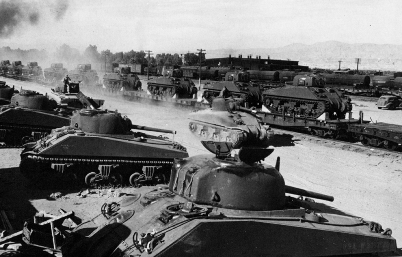
Another prototype example, in this case Sherman tanks almost exclusively loaded on 50-ton flat cars, thus one tank to a car, is this photo from the Southern Pacific in Indio, California, of tanks being unloaded for desert training in 1942. (U.S. Army Signal Corps photo)
I want to vary my armor loads, since I don’t plan to try and operate any full trains of military equipment. Instead, my loads will depict individual vehicles being moved from one training facility to another, or perhaps in a repair cycle (waybills of course will reflect that).
The waybills I use for military moves on SP’s Coast Line take advantage of the presence of Camp Roberts, home of the 7th Armored Division at the time I model. Here is one example of a waybill I might use for the two-vehicle load shown above. It is a U.S. Government waybill since this is government property:
This bill, which happens to have been filled out with a Teletype type face, reflects a movement from what was the primary Army armor facility in 1953, Fort Hood, Texas, to Camp Roberts.
Armor loads allow some indication of the recent (for my layout) Korean War and training in its aftermath, and in addition are suitable for my layout’s locale on SP’s Coast Line.
Tony Thompson
Monday, September 23, 2019
Fixing fragile sill steps
Most of us are familiar with the fragility of styrene sill steps on freight cars, and even when tougher engineering plastics are used for these parts, they simply are not really durable. Now, a person who builds models for a display case, or who only operates his layout himself, may not break very many of these steps, but a layout that has various populations of visiting operators from time to time will certainly break a fair number.
Before saying more, I should credit my late friend Richard Hendrickson, who insisted that the first thing one should do with a “ready-to-run” (RTR) freight car — which he always referred to as “ready-to-finish” — was to slice off those fragile sill steps, and replace with sturdy metal, such as A-Line bronze steps. So in this context, when I say “fix” the steps, I really mean “replace.”
Alas, I am not so meticulous or rigorous as was Richard, and I must confess that often I have put new RTR freight cars into service (after weathering, which was Richard’s second step). It’s only occasionally that I take the trouble to replace sill steps before operating a car.
But naturally in due time, in the course of multiple operating sessions, the original sill steps do break. On the prototype, a missing sill step would be immediate cause to direct a car to the repair track, but I may wait until two or more steps are missing before sending the car to the workbench.
Once there, cars may accumulate until I am in that “fix the darn steps!” mood, and then I undertake a whole batch of cars with the same repair need. I’ve described my technique in this blog previously, but will repeat part of it here, while showing another feature of my approach.
Because I find I don’t have the accurate drilling ability to drill into and parallel to the car side, thus locating new steps right where the old ones were, I begin instead by gluing styrene blocks behind the sill to serve as backing. I usually use HO-scale 4 x 4-inch styrene for this, cut to fit the length of the new sill step. Here is how it may look at this stage.
Then I drill into the styrene block, or between the block and the car side, with an appropriate-size drill in a pin vise. For most freight cars, this drilled hole will reach all the way into the car interior, which is helpful for steps with long attachment pins. Usually I then put a little CA onto the step and slide into the holes, or, if not confident of the smoothness of installation, I install the steps, then add a drop of CA at the surface, to wick into the hole and complete the joint.
For the car you saw in the photo above, I decided to use some of my stash of Tuttle Industries sill steps, a marvelous product that unfortunately did not survive long in the market. These are so-called “Style B” steps, meaning the leg toward the car center is angled. This is written on the package label.
These have a great looking cross-section and nice, sharp corners, unlike A-Line steps, though I will admit that when painted a dark color, such as boxcar red or Pullman green, details like corner shape are hard to appreciate. But on some cars, I do like to use the better steps. Here are two of the Tuttle steps, just having been inserted into the styrene blocks as described above.
The completed car, with steps unpainted so they will show up better, looks like this (it’s a Proto2000 model, quite close to the Southern Pacific’s Class A-50-14). You may wish to enlarge the image by clicking on it.
I don’t wish to give the impression I don’t like or don’t use A-Line steps. I certainly do, by the dozen. Here is just one recent example, again unpainted, on a PFE express car. It’s an InterMountain model, with trucks modified to represent the Chrysler trucks used on 25 of these conversions of Class R-40-10 reefers (for more, see my post about creating these trucks: https://modelingthesp.blogspot.com/2016/02/pfe-40-foot-express-cars-part-2-trucks.html ).
As I see it, this kind of step replacement (really, step upgrade) is a necessary part of maintaining the layout car fleet. Occasional damage such as the loss of a sill step, is a small negative, when measured against the fun of operating sessions, and in any event, the resulting repairs are not difficult.
Tony Thompson
Saturday, September 21, 2019
Comments on modeling the Fifties
I was stimulated to think about my approach to modeling the 1950s recently when I received an email from a modeler I know slightly, asking for advice on how to go about modeling the transition era. He is not old enough to remember it himself, and has liked some of the 1950s layouts he has seen, so wondered what I would advise. He does want to capture the “look and feel” as well as he can, and hoped I could recommend resources.
To some extent, this same question could be posed for any decade of interest: what are the resources you need to model accurately? As I have just hinted, this will depend to some extent on how serious you are. Plenty of what I suppose could be called “modern modelers” seem content to include locomotives and rolling stock typical of the 1970s to the 2010s, all in one layout. But let’s imagine that you are serious. I will illustrate for the 1950s, though I think principles here are broad.
My first comment to my correspondent is that there are at least two excellent publications out there that focus on the 1950s. I will start with what I still believe to be the best of these, a Special Issue of Model Railroader from 2011 (and like all the first four Kalmbach publications mentioned in the present post, still available for purchase on-line at Kalmbach; I just checked).
It covers not just rolling stock, but structures, vehicles, and even operations. I cannot praise it too highly for anyone wishing insights into the 1950s.
What I would call the “other best” publication on this topic, Modeling the ’50s, subtitled “The Glory Years of Rail,” is also from Kalmbach, and packed with excellent material.
There are two additional publications I would mention on this topic,more narrowly focused but still very fine, both from Kalmbach. The first I would mention is a typically good Tony Koester book, Modeling the Transition Era, focused more on rolling stock, but well illustrated and quite complete. (I am not an entirely neutral commentator here, as I contributed some of the photos in the book).
Last of these four titles is what to me is an important aspect of model railroading, freight cars, has been very skillfully and surprisingly completely covered by Jeff Wilson’s book, Freight Cars of the ’40s and ’50s, published in 2015.
Another excellent source, though not restricted to the 1950s, is the Jeff Wilson series of “industry” books published by Kalmbach. I showed the covers of all four in a prior post, and mentioned a little of what is in them. This is a very useful set of snapshots of how industries worked (see my post at this link: https://modelingthesp.blogspot.com/2018/01/handout-for-traffic-talk.html ). These are the only publications mentioned in this post that are not all in print, but any not in print at Kalmbach are readily purchased from used book dealers on line.
That “industry” series is now being supplemented from Kalmbach with separate full books on some industries, such as coal, livestock, produce and so on. You will recognize these easily on their book sales website at: https://kalmbachhobbystore.com/catalog/books .
Finally, I want to mention a Kalmbach publication I have recommended before, but will mention it again because it addresses another aspect of model railroading that I find vital to the hobby, operation. Now there are lots of books on operation, but as an introduction, I find this Special Issue of Model Railroader, entitled How to Operate Your Model Railroad, to be without peer. If you are new to this topic and would like to learn about it painlessly, you should try this title.
These are all titles I recommended to my correspondent, and he seemed pleased to be directed to some sources he could absorb at his own pace. You may wish to do the same.
Tony Thompson
Wednesday, September 18, 2019
Roco flat cars, Part 7: armored vehicles
I have posted several descriptions of military vehicle loads in
recent posts, primarily intended for the heavy-duty Army flat car
modeled by Roco and which I upgraded for use on my layout. The most recent of those loads
were half-tracks, described in this post:
https://modelingthesp.blogspot.com/2019/05/roco-flat-car-part-6-more-about-half.html
. But of course the heavy-duty Army flat car (of 100-ton capacity) was intended for much heavier loads than half-tracks.
The most common load that one thinks of in mentioning armored vehicles is a tank. My modeling year is 1953, and although by that time the Sherman tank, mainstay of World War II, was all but officially obsolete, it had been used to some extent in the Korean War, only just ended in 1953 (the armistice was signed in July), and was definitely still in use for training purposes in the United States.
There have been HO scale models of the Sherman tank available for some years. From a model railroading perspective, these can be flat car loads. One can find a variety of photos of Shermans loaded on flat cars, and they are of interest if one wants to model them so loaded.
Here is one example, a Signal Corps photo taken in the U.S. of a Sherman ready for shipment. It is loaded on an Illinois Central flat car with overhanging deck, that is, with a deck which extends out to the outer face of the stake pockets. This car, IC 60636, was a 50-ton flat car, adequate for the various Sherman variants, which ranged in weight from 34 to 41 tons (most Shermans were in the lower part of that range). But notice that only one tank could be carried on such a flat car. Also note, incidentally, the complete lack of visible lettering on this tank. It may have been used in maneuvers.
Careful examination shows that there is a minimal chock under the front and rear of the tank treads, and a heavy timber (actually two stacked timbers) alongside the tank (probably spiked into the deck). There is a pair of steel rods from the towing hook under the glacis, to a stake pocket on each side, but this is nearly invisible even in this view, and it could be omitted in HO scale.
This degree of blocking of the vehicle may seem rather inadequate, but was not untypical of how tracked vehicles were shipped on flat cars. Shown below is a Richard Steinheimer photo, used with permission, taken of course to show SP Trainmaster 4801 powering commute train 114 on the San Francisco Peninsula, but from the photographer’s vantage atop a lumber load, we also see a couple of heavy Caterpillar bulldozers dominating the foreground, and the blocking applied to their treads.
I have taken a similar approach, with chocks at each end of the tank treads and a scale 6 x 6-inch timber alongside. The model tank is a Roco Sherman, and the lettering is from Microscale set MC-4279. On a 50-ton flat car like this Union Pacific car (built from a Westrail kit), this would be a single-vehicle load, as already mentioned in connection with the IC flat car above. It’s shown on my layout.
This kind of armor load is credible on my layout, with a destination of Camp Roberts, home of the 7th Armored Division in 1953 and an armor-training facility during the Korean War, located just north of San Miguel, California, right on the SP Coast Line, railroad west from the locale of my layout.
A tank like this is of course an even more appropriate load for the Roco Army flat car. That heavy-duty flat car was intended to carry two vehicles of the weight range of a Sherman tank. I will return to armor loads for the Roco flat car in a following post.
Tony Thompson
Sunday, September 15, 2019
Modeling SP passenger cars, Part 9
I have done several previous posts about Southern Pacific passenger cars, as you can see from this being the ninth in the series, and there are even more if you include the ones about specific trains such as the “Coast Mail,” along with a kind of sub-series on SP sleeping cars, that included five posts. Lastly, there was a three-part series on making various heavyweight sleepers by modifying AHM cars (you can find any of those prior posts by using “SP passenger cars” as the search term in the search box at right).
My present post is about head-end cars, and accordingly follows on the Part 2 post, which began discussion of those kinds of cars (you can read the Part 2 post at this link: https://modelingthesp.blogspot.com/2012/10/modeling-sp-passenger-cars-head-end-cars.html ). Then the most recent post in the series that treats head-end cars is the preceding post (see it at: https://modelingthesp.blogspot.com/2018/04/modeling-sp-passenger-cars-part-8-more.html ).
I have acquired a couple more of the old Ken Kidder brass 60-foot baggage cars, and am gradually getting them fitted up for layout service. As I pointed out in previous posts. the Kidder roof meets the car side at an angle, rather than curving to be tangent to the side, but this isn’t evident in a passing train. Likewise, the Kidder roof vent arrangements are at best unusual for SP “Harriman” cars (I have been told they are accurate for several Illinois Central cars), but again, what matters in a passing train is that there are roof vents, not the exact arrangement (at least for those other than passenger modelers, of course).
Shown below is the kind of underbody additions that I have applied to some of the Kidder baggage cars, with a battery box on one side, brake gear on the other side, with a reservoir. The lighting makes it look like it is a light color, but is actually dark gray. And yes, those are Central Valley trucks, of which I wish I had more.
The photo below shows another of the cars being completed, SP 6206, in this case using Athearn 4-wheel trucks. I have experimented with a more faded green, both because some SP cars had that look, and in respect of indoor lighting. The full prototype color, Dark Olive Green, looks very dark indeed in indoor lighting and I have used it only for a few cars, to suggest recent repainting. The car below has been weathered, though I note that the trucks need some more grime.
In most operating sessions, I do include a passenger extra, or a section of the “Coast Mail,” as suits the timetable. For this, I usually choose a Class P-4 Pacific, since the train is not very big. An example is shown below at Shumala. This particular train is mostly baggage cars, with an express box car (AAR Class BX) on the head end, an RPO car behind the baggage cars, and a dead-head sleeper on the rear. The express box car is from a Sunshine kit.
Passenger operation is not a very important focus for my layout, but I do like to include this much of a passenger train presence. And it’s enjoyable to provide this kind of a variation in what is otherwise mostly freight car modeling!
Tony Thompson
Thursday, September 12, 2019
VanRail 2019
For a number of years, the modelers in Vancouver, British Columbia, have hosted an operating weekend in alternate years. If I’m counting correctly, this year was the seventh in this series. I attended, as I have previously, and as always, tremendously enjoyed a well-run meeting with terrific layous. This year, the group returned to the nice Accent Inn in Burnaby, not used in 2017 but familiar from prior years.
Among the most ambitious and impressive layouts I know of in the Vancouver area is Scott Calvert’s Boundary Subdivision of the Canadian Pacific. As was the case two years ago, I worked one end of the big yard at Nelson, under the able yardmastering of Travers Stavac (it was pointed out that with Canada going metric, this job will eventually be retitled as the Metermaster). Right above the yard was the new second level, and we enjoyed seeing a train up there, one of the first to run on this very recent trackage. You can see the excellent rockwork and part of a snowshed, though scenery is clearly in its early stages.
Scott also hosted a very pleasant social evening on the Friday of the meeting. Thanks, Scott!
My second layout was the Pacific Great Eastern of Doug Hicks. This is a remarkable layout in the amount of trackage that Doug was able to include in a modest-sized room, and the trackage all ran well, too. The scenery was nearly complete and quite nice, and that made it enjoyable to view and to operate. I ran the North Vancouver yard, compact and busy enough to be a challenge at times, but operating flawlessly. Here’s a view looking toward the rest of the layout (the relatively few cars that are visible show why I had enough time to take a photo).
Doug has made an interesting solution to knowing how a slip switch is lined, by adding LED lights that illuminate the chosen tracks. I totally relied on this in working the yard!
On Sunday I had he privilege of operating on Mike Chandler’s Western Midland layout, set in 1938. Though work remains in some areas, the scenery is outstanding and so was the quality of operation. I had the fun of running several different way freights, with lots of very nice switching.
One feature I liked, and it’s one you rarely see, is that the whole fascia was used as a kind of control panel. Below is part of the fascia at Black Mountain. The color-coded circles at mid photo, and corresponding plugs at the fascia bottom, are for DC operation, something Mike rarely does.
The white lines are essentially a 1:1 track diagram, making it easy to find the pushbuttons for track switches, and there are handy racks for paperwork (in use at the top of the photo). Boxes at right are for waybills, and you can see a hand-held throttle attached to Velcro at the left bottom. Nicely thought out.
The scenery, as I said, is very impressive. Below is the summit of the railroad’s mountain crossing, at Lofty, with a wye that you can see, along with a stamp mill for a mining operation. Fun to switch as well as very attractive.
I really enjoyed all three of these layouts, as you can probably tell. Even so, at most of these weekends, one has the experience of hearing multiple people rave about one of the layouts, inevitably one that you did not get assigned to. I just patiently make notes, so I will know to request that layout next time! Thanks again to the Vancouver crew, who put on a terrific event.
Tony Thompson
Subscribe to:
Posts (Atom)