Friday, July 29, 2022

Re-working an Ulrich “War Emergency” gondola

 Last March, I posted a preliminary description of the work I wanted to do to model a “War Emergency” gondola. These cars were a World War II design to use wood side sheathing to save steel for the war effort. I have a 1950s Ulrich model of such a car, that I want to recondition and upgrade for use on my layout, as I described in my first post. (To see that post, use this link: https://modelingthesp.blogspot.com/2022/03/the-ulrich-war-emergency-gondola.html .)

My first step was to make a new floor, representing cross-wise planking. I used Evergreen V-groove sheet no. 4080, about 8 scale inch width boards. I gouged it to show wear in use, then primed it with Tamiya Fine Surface Primer, the white color. It will be painted an “aged wood” color later.

Let me note that the prototype cars, when built, had interior wood surfaces that were left unpainted, as you see in the photo below (Despatch Shops photo, via New York Central Historical Society, from the excellent Ed Hawkins article on the War Emergency gondolas in Railway Prototype Cyclopedia, No. 28 (RP Cyc Publishing, 2014). Many War Emergency gondolas received fir side sheathing and yellow pine floors, which may be the case here.

After the war, it was expected that owners of these gondolas would likely replace the wood sides and floors with steel. Many railroads did so, including NYC, over a period of years. Since the Ulrich model has wood sides, it has to represent one of the minority of NYC cars that had not yet gotten the steel replacement. By 1953, my modeling year, the Official Railway Equipment Register (ORER) shows that 111 out of 698 NYC cars had not yet become all-steel.

Returning to the model, I cleaned up the interior to receive the new styrene floor, removed the incorrectly located hand brake housing, brake cylinder, and AB valve ( as I showed in the first post, link in the first paragraph above). I relocated the valve and cylinder according to the Richard Hendrickson model I showed in the previous post. The I glued the new floor in place with canopy glue.

For the lever hand brake (see prototype photo above), I decided to approximate it for this less-than-contest-level model. I flattened the end of a length of 0.029-inch brass wire and fitted that into the old handbrake mechanism. Said part is not the Klasing mechanism, but it will do for this model. The lever is oversize because I wanted it to be visible. 

I repainted the model with Tamiya “Red Brown” paint, followed by a coat of gloss. As I mentioned in my first post (see link in first paragraph, above), I have a set of the very nice Greg Komar NYC gondola dry transfers. These are fairly old, however (Greg has been out of this business since 2013), and in my experience older dry transfers are, shall we say, imperfectly reliable, particularly small lettering.

Accordingly, I tried transferring the Komar lettering onto blank decal paper. This can then be given a protective coat of flat finish, and used like any decal. And sure enough, the smaller lettering did not transfer very well. I decided to substitute a set of Tichy decals, set 10154.

Below is the model at this point. The floor is in place, and both it and the lower interior walls need to be painted an aged wood color as the foundation for weathering. Lettering as NYC 711318 is complete, along with a reweigh date appropriate for my modeling year of 1953, and some preliminary decal graffiti. 

I decided to hand-paint the wood coloring. I used some old Model Master paint that was mixed from Roof Brown and Light Gray to make a kind of dirty medium brown. Since the “wood” parts would then be heavily repainted with acrylic tube paint (not washes), exact color didn’t matter, just not white. That interior painting was preceded by the usual acrylic washes on sides and ends.

The exposed wood parts of the model, interior side walls and floor, were painted with mostly Burnt Umber, with some admixture of Neutral Gray and Black (I used Liquitex acrylic tube paint). Some areas were marked to suggest spillage or other events in the car’s history.

Once the entire car body was weathered, I installed Kadee couplers. As I always do nowadays, I used whisker models. These are reliable and can be installed well even in coupler boxes not exactly of Kadee dimensions. 

Normally these would be the “scale head” size, no. 158, but I also have some no. 148 couplers around, the old “No. 5” standard head with whiskers, and don’t hesitate to use those. In my experience, well-installed and maintained no. 5 and no. 158 work well together.

At that point, I added the trucks. As this is a 70-ton car, I wanted to use 70-ton trucks. It’s true that they look a lot like 50-ton trucks, but the wheelbase is longer, so they very definitely are not the same. My choice was Tahoe Model Works No. 110, an ASF A-3 truck. This is a postwar truck and would not have been on the car when new, but after the war, may cars received more modern trucks like the A-3.

With all weathering done, along with a few graffiti and route cards, here is the car, ready for service.

It was fun to re-visit one of these classic Ulrich freight cars and bring it into service on my layout. I enjoy that my car fleet has a mix of the latest resin or ready-to-run styrene freight cars, along with “oldies” like this one.

Tony Thompson

Tuesday, July 26, 2022

Making a depot platform

 Passenger depots almost always had a paved platform of some kind. Concrete, brick and asphalt were common, sometimes a replacements for older wood-plank platforms. I even know of a couple of examples where the platform was partly gravel, but this must have been less comfortable to walk on or to move baggage carts. 

Looking just at Southern Pacific practice, plenty of depots had asphalt platforms in later years, but concrete was common too. I only know of one SP example that was brick. Most depot photos are taken from ground level, making it hard to distinguish platform materials, so research is challenging. There are a great many depot photos in Henry Bender’s book, Southern Pacific Lines Standard-Design Depots (Signature Press, 2013), for example, but few offer a clear view of the platform.

On my layout, I have tried to simulate asphalt platforms at Shumala, using plaster painted a faded asphalt gray.

The depot at Ballard has a platform intended to resemble concrete, scored with squares as is done in sidewalk. This is easy to model, since Evergreen makes a styrene  “sidewalk” sheet with various sizes of squares. That’s what was used here.

But so far, the depot at Santa Rosalia doesn’t have a platform. The depot itself is one of SP’s standard designs , as fully described in Henry’s book, a Common Standard No. 22 (an American Model Builders kit no. 134), as I’ve described (see this post: https://modelingthesp.blogspot.com/2015/05/sp-depot-santa-rosalia-part-4.html ). The trackside area is now represented as dirt.

Whatever material I choose for the platform, it will be a uniform surface, and needs to fit the space. The simplest way to accomplish that is to make a pattern. I used some waste cardstock and cut and trimmed it until I was satisfied with the fit. I also made the pattern a little longer to the right of the pattern you see here.

Next came the choice of materials. I decided that concrete seems sensible, and I have some Evergreen no. 4517, “Sidewalk,” in 3/8-inch squares. Now it was just a matter of transferring the pattern to the styrene sheet. My pattern is 13.5 inches long,  longer than the Evergreen sheet as supplied, so I needed to splice two pieces together. I glued some 0.005-inch styrene sheet to the back of the joint.

Next came coloring. This platform represents concrete, so should look like that material. The usual “modeler’s version” of concrete is a gray that is darker than medium, a good representation of freshly installed concrete, but not what concrete looks like after it’s been in place for a few years.

With age and wear, concrete tends to take on the color of the sand and gravel that it contains, which is rarely gray, and often a warmer color. One option is the Model Master “aged concrete” color (no. 4875), though it is a pretty warm color. I decided to mix it, about 2:1, with Light Gray from the same manufacturer. My “concrete” surface was then given a dirty-gray acrylic wash. 

Here’s how it looked. As it always does, the wash tended to deposit pigment in the grooves in the styrene, highlighting them somewhat and making them more visible. The big notch is for the bay window of the depot.

Next came installation. Although I don’t glue down or otherwise attach the structures on my layout, I do glue things like platforms. This one was attached with canopy glue.

This finishes the immediate depot area at Santa Rosalia. Another item on the “to do” list that’s checked off. Progress is always fun!

Tony Thompson

Saturday, July 23, 2022

My train at BAPM, Part 2

 Last month, the annual series of Bay Area Prototype Modelers meets (BAPM) resumed after a pandemic hiatus. I attended and as always, greatly enjoyed seeing the models displayed by other attendees (for some of the highlights, see this post: https://modelingthesp.blogspot.com/2022/06/bapm-2022-part-2.html ). 

As I usually do when I attend BAPM, I brought an entire train to display at the 2022 meet. The first half of the train was shown in a prior post (here’s a link: https://modelingthesp.blogspot.com/2022/07/my-display-train-at-bapm-2022.html ). The present post continues with the remainder of the train.

The last car shown in the post just cited was an Ulrich Southern Pacific GS gondola. Behind it in the train was this 4-truck flat car, SP 44095, with a very large load, a steel casting from Mesta Machine of Pittsburgh. As I noted in the information slip next to the model (below), this load was produced by Multiscale Digital LLC (visit them at: https://multiscale.digital/ ). For my modeling, see: https://modelingthesp.blogspot.com/2020/05/impressive-flat-car-loads.html .

Following that car was this SP covered hopper, weathered to show that it’s been in cement service. It’s an InterMountain ready-to-run model of a fairly new car in my modeling year of 1953.

The next car in the train was this PFE reefer, a member of the large R-40-23 class, repainted into the post-1952 paint scheme. It’s an Evergreen Roundhouse custom-decorated Athearn kit with some detail upgrades.

Behind that car was this one, P&LE gondola 40205, built from a Proto2000 kit. Its load is Evergreen H-columns, painted to resemble bare steel, a common type of load in this road’s gondolas.

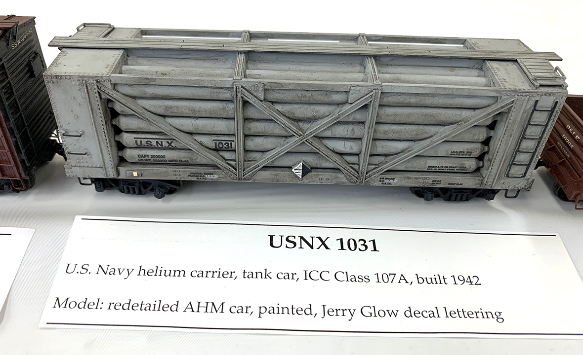
The next car in the train was a helium car, still in U.S. Navy service at this date, USNX 1031. The model is an extensively modified AHM car, with decals from Jerry Glow and (on this side) an Empty placard. I posted about this model previously; see: https://modelingthesp.blogspot.com/2012/11/helium-cars-part-3.html .

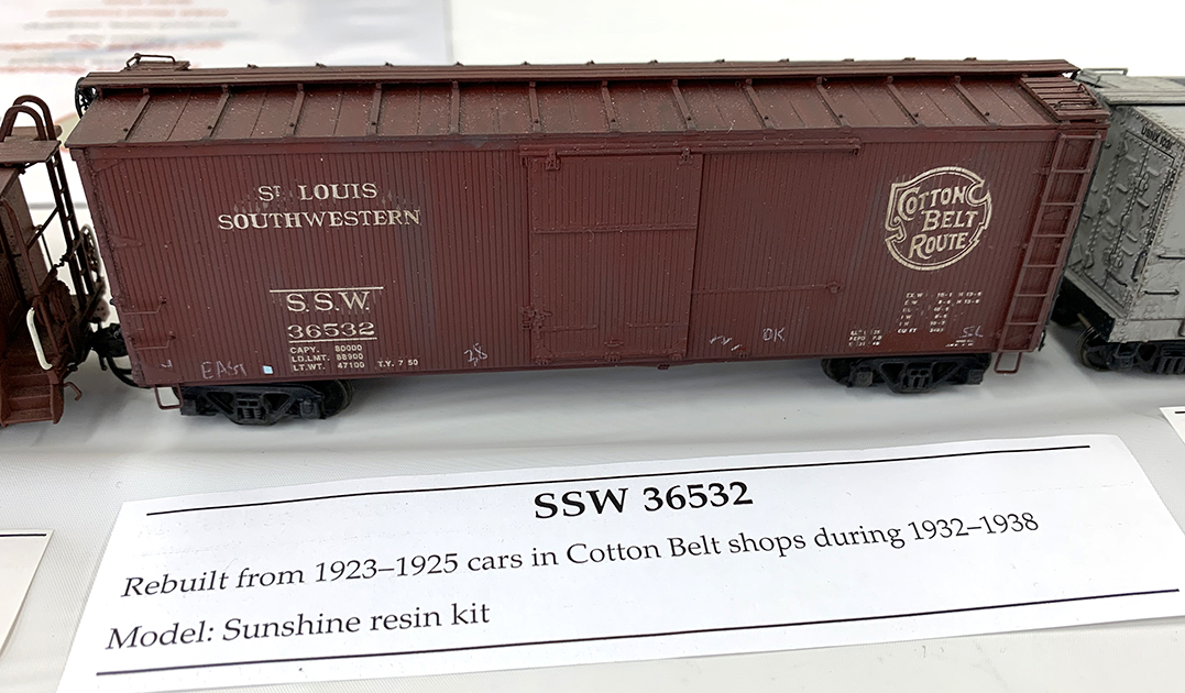
Following that car was the last freight car in the train, a Cotton Belt rebuilt box car, with some of the distinctive Little Rock Shops work in modifying the ends for an increased-height car. It was built from a Sunshine resin kit.

Finally, of course, came the caboose, and like the locomotive, it’s a Balboa brass model, SP 1205, a steel caboose of Class C-40-3.

And just to show the full scope of all this, here is an overview of the whole train, locomotive at right:

It is fun to pull together a selection of cars for a train like this, and to decide how to make up the information slips that will convey to viewers what the model is, and what it is intended to represent. I had fun doing it this year, and expect to do so in the future, too.

Tony Thompson

Wednesday, July 20, 2022

Modeling cab aprons

 This post is about including cab aprons on model steam locomotives. So what the heck is a cab apron? (I hear you mutter.) For railroad terminology, I go to the Cyclopedias, in this case the Locomotive Cyclopedia for 1925, the 7th edition published by Simmons-Boardman. On pages 108 and 109 are a drawing of a generic Mikado (2-8-2) steam locomotive and the names of 324 different components of the locomotive. 

Below I show just the cab portion of this drawing. Note at the right edge of the cab that an item 211 is called out, Below the drawing I show the entry in the list of names, for no. 211. It’s the cab apron. This is a steel plate, hinged at the cab edge, which provides the walkway between engine and tender. Attached to only one of them, it allows the tender to move relative to the locomotive, for example in curves, while maintaining a walking surface over the gap.

This part is needed in model steam locomotives in particular, because we typically couple locomotives and tenders at considerably greater distances than the prototype (because of our far sharper curves in model track). Below is an example of such an apron, in this case on a Key brass model of an SP Consolidation. The apron is brass, and has masking tape underneath to ensure against electrical shorts.

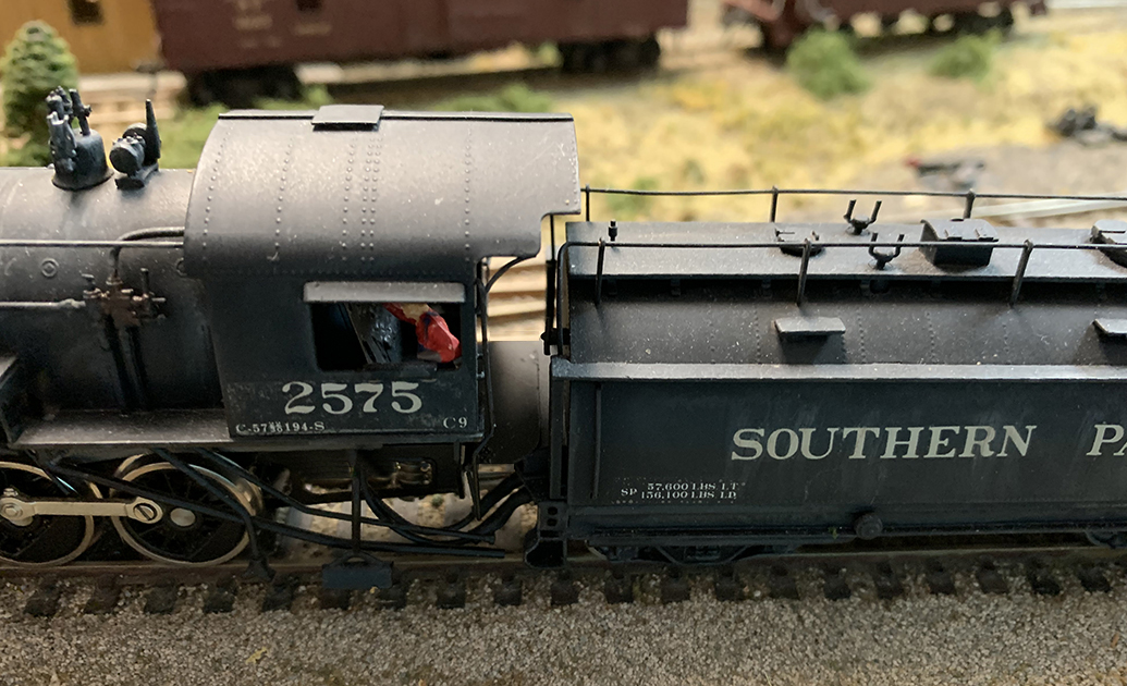
When an apron is not included in the model, it certainly emphasizes the gap between engine and tender, as you see below on SP 2575, a Sunset model of an SP Class C-9 Consolidation with a whaleback tender (shown on the turntable at my layout’s Shumala engine terminal). We normally view our models from a somewhat overhead perspective, making these gaps more obvious.

To add aprons like this, I have usually used sheet styrene, 0.010-inch thickness, though the exact thickness isn’t important. Styrene gets you away from the electrical risks of a brass apron. I have just used ordinary Scotch mending tape to form a hinge underneath the apron. 

In HO scale, a locomotive cab is about an inch wide, though each individual cab has to be examined to see where the apron should be located. Usually the gap is around a quarter-inch. I usually make the apron a bit wider than that, maybe 5/16-inch. They are painted flat black.

Below are some examples of various aprons I have made. The one at upper left, with rounded corners, is the design I mostly use. The two bottom examples have diagonal corners of different size. All are an inch wide and roughly 5/16-inch high.

With an apron like the rounded-corner one shown above, I corrected the appearance of SP 2575, pictured above on the turntable. Here it is with its styrene apron.

Though these aprons are a detail, and a model one at that, since on the prototype they are quite narrow, I really think they improve appearance. And like so many “errors,” once you have noticed them, it becomes impossible to “not see” them. I’ve enjoyed adding aprons to my locomotives that didn’t have them.

Tony Thompson

Sunday, July 17, 2022

My article in the July 2022 MRH

In the new issue of Model Railroad Hobbyist or MRH, dated July 2022, my article (part of the “Getting Real” series) is entitled “Fitting an Industry into a Tight Space.” It is about one of the last industries to be built for my layout, the imaginary Santa Rosalia Branch of the Southern Pacific. The industry is a kelp processing business, appropriate for the town of Santa Rosalia along the Pacific Ocean shore.

For a lot of years, I used the bottom part of a kit box, inverted, with the industry name lettered on the “top” of the box, to stand in for industries not yet built. Eventually I decided that was too prominent, so went to a simple paper slip with the industry name, placed about where the industry would go. The photo below (from the article) shows the site discussed in the article.

This is the spot where the new industry had to fit. You can see that most of the site, alongside Laguna Street right next to the fascia at the front of the layout, is just painted Homasote. The problem that I solved in the article was that the site is narrower than the kit that I chose to build.

I chose the “Carnegie St. Manufacturing” kit produce by my late friend Jim Sacco’s City Classics. I liked that it’s a cement-block building, of which I had none on the layout, and that it’s not “cute,” as are so many structure kits. Below is one of Jim’s photos of the kit, showing one way it can be built. It’s actually a fairly flexible kit, offering a number of possible configurations.

As I mentioned, my site is narrower than the City Classics kit, so I narrowed each of the end walls and then assembled the structure. Though this is fairly straightforward kit-bashing procedure, I showed each step in the article, in hopes of being perfectly clear about the simple steps needed. 

After assembling all four walls and one of the office extensions, along with painting windows and doors, the building looked like this from the back or track side (which is not viewable from the aisle of the layout). Roof is not yet painted, structure is not weathered.

Once the structure was weathered, signage added, and some Walthers “Roof Details” (set 3733) placed, it looked like this on the front side.

Finally, of course, the structure was placed on the layout and some scenic details added, along with a concrete driveway for the large delivery door and for parking at the far end. In the distance at right, you see the Santa Rosalia depot, one of SP’s distinctive Common Standard No. 22 structures, and in the background is the Martinelli Bros. fish cannery. 

The last point to be mentioned in the article was some detail about kelp processing and the various kelp products which would be shipped out of this building. I even included some sample waybills to illustrate the inbound and outbound loads. But I won’t repeat that discussion here.

This industry fills a gap on the layout, and in the group of marine-oriented industries here in coastal Santa Rosalia. I’m glad to have it on the layout.

Tony Thompson

Thursday, July 14, 2022

PFE Class R-30-24 plywood car, Part 3

This project is a collection of parts, most given to me by Frank Hodina, to build a plywood-sheathed reefer of PFE Class R-30-24. In the previous post, I showed my pre-painting of all external car parts except the floor, and also showed use of Coffman corner clamps to assist in making square corners in assembling sides to ends. I was pleased with how neatly the clamps assisted me in making those corner joints. (To read that previous post, got to this link: https://modelingthesp.blogspot.com/2020/09/pfe-class-r-40-24-part-2.html .)

In the previous post,  I had made up two side-end pieces. I next joined the two remaining joints using the same method with the Coffman clamps and the 1/8-inch styrene strip inside each corner. After the first pair of side-end combinations, I made the final two joint in the same way, using the Coffman clamps. Once all glue was set and everything looked as it should, and the roof fit perfectly, I attached the roof with CA, completing the body box.

Meanwhile, I turned my attention to the floor/underframe part of the car. When working on components like this, I prefer to complete any drilling and tapping before adding any delicate parts. So my first task was to drill and tap 2-56, the truck screw holes in the bolster, and the coupler box attachment screw holes.

Next I narrowed the floor a bit to fit into the box, and then attached the car weights inside (atop the floor). I used my usual car weights, a pair of 5/8-inch steel nuts, held down with canopy glue. I’ve identified one end as the B or “brake” end.

Next, I turned the floor over and added the coupler boxes (so they could get painted with the rest of the underbody). With that done, I could proceed with adding the cross-bearers. For a glimpse of the prototype, here is an interesting Pullman photo (1926; courtesy Donald Duke) of a Class R-30-13 car, with the underframe whitewashed.

 In this photo, you can see the four cross-bearers, and their curved ends. This is the “railroad-design” (as PFE called it) built-up underframe with twin center sills. Note also that the brake cylinder (seen on the other side of the center sill) is not below the sills.

The model parts I was given included white metal castings of these crossbearers. I simply attached them with canopy glue. In the photo below, the floor is resting on the steel nuts. 

The next step was to add brake gear. At the time of the plywood rebuilds, AB brake gear had been standard for many years. I used a spare InterMountain brake set, and cut it into two pieces to fit around the double center sill.

This has gone well so far. Next I need to add the body details, to which I will turn in a future post.

Tony Thompson

Monday, July 11, 2022

Family ops —— again

Throughout the pandemic, my granddaughter has visited us from time to time, and she really likes to operate on the layout. We usually set out one of the Accurail cars that I helped her build, and that belong to her (for links to earlier descriptions, see: https://modelingthesp.blogspot.com/2020/07/pandemic-operating-sessions.html ). Currently she is in Berkeley for two weeks of summer camp, and we had the chance over the weekend to operate again.

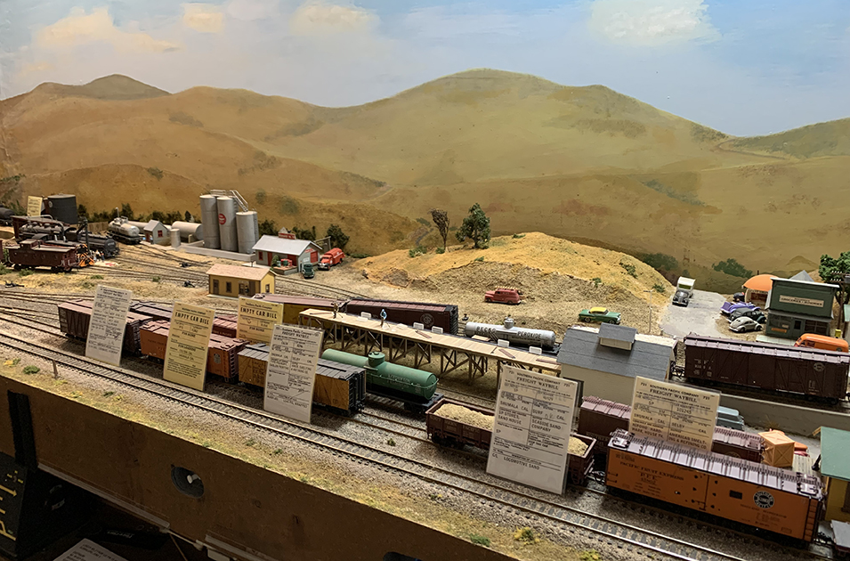
She’s now ten and a half, and increasingly can understand waybills and figure out how to use them to plan switching moves in a session (so much for the adults who claim it’s just too complicated . . .). By now, I can set up as many cars for her to switch as would be the case in a  typical adult operating session. As you see below, at the beginning of the session (at Shumala for this version), the waybills were leaned up against the cars to make sure all were identified.

Then began the work of doing all the switching that was called for. First step, bring out the switcher from the engine terminal service area. Here she is doing that, and shortly will be removing all the waybills from the layout surface. I don’t mind waybills set out this way before the session starts, but don’t want the bills on the layout, once operating begins.

Next she planned out how the car order in the working string should be, and carried out a run-around by the engine to get that started, moving down to the far end of the Shumala siding. She’s quite skillful by now with the NCE throttle, including use of horn and bell.

She worked steadily through all the switching, step by step, with only a few false moves. In the photo below, she is nearly finished, just about to complete a move to the house track at the depot.

It’s always fun to have an enthusiastic operator, and I know she enjoys doing this stuff. Hopefully her interest will continue. And of course I enjoy seeing the layout used as I had intended it to be.

Tony Thompson