Reference pages

Friday, March 29, 2019

Structural steel loads

In a number of posts over the years, I have described a variety of loads for open-top cars. I find these not only interesting, but a great way to vary what particular freight cars are doing in an operating session. Of course the range of topics is broad, and you can find a lot of the prior posts by using the search box at the top right of this page, with the search term “open car loads.” In the present post, I want to explore an additional type of load, structural steel.
     In the steel business, “structural” refers to specific shapes, such as channels, I-beams, H-beams, and so on. There are lots of “other” shapes, but the term “structural” is restricted to the widely used ones. These are typically hot-rolled shapes, and often are cold-straightened before shipping, as the shapes emerging from the hot mill often bend or warp as they are completed. From numerous trips to steel mills when I lived in Pittsburgh, I know well what these processes and products look like.
     I mention the straightening process because of how the steel looks when finished. Plate steel and some shapes are usually shipped as-hot rolled, and will then be coated with what is called “mill scale,” essentially iron oxide in a medium gray color that formed while the steel was hot. This is a familiar appearance around a steel mill. But when steel is cold-rolled, cold-finished, or straightened, the brittle mill scale breaks off and a typically dark metal color is left. This is not the “shiny silver” look of cleaned or polished metal, but a much darker color. I wanted to model some structural steel with this color.
     I should mention that if steel is stored awhile out in the weather, it certainly begins to show rust, so rusty steel loads are perfectly appropriate. And sometimes the steel will have received a coat of primer or paint, often red lead or equivalent, especially if the steel has been fabricated to size and is ready to install. So there are actually several colors that might be observed for steel loads.
     Just as illustration of what I wanted to do, there is an apartment building starting construction near me, and when I walked past the site the other day, they had a couple of large steel I-beams delivered. This is what they look like, a good example of the very dark gray type of appearance. (You can click on the image to enlarge it if you like.)


     I decided to choose a new shape of material to make some new steel loads. One nice option for gondola loads is the excellent I-beams offered by Evergreen. I like the bigger examples, like their part no. 278, characterized as a 5/16-inch beam, which in HO scale is about 27 inches deep. A few lengths of this shape in a car amount to a reasonable load. How reasonable? One classification widely used for beams like this is the W (for wide-flange) series. The Evergreen 27-inch beam has about a 12-inch flange, making it approximately a W27-130 beam, meaning it would weigh 130 pounds per linear foot.
     This means that a scale 40-foot length, say, would weigh 5200 pounds. Three such lengths would weigh 15,600 pounds, and six of them would weigh 31,200 pounds. These are all readily accommodated in a 50-ton freight car.
     I mention these weights because the Evergreen no. 278 package of two (actual) 14-inch I-beams then contains about 31,000 pounds of steel in HO scale. Use more packages if you want a bigger load, but several packages might be too much.
     I began by cutting an Evergreen beam into three lengths to fit into a 40-foot car, not exactly equal length since structural steel is often not cut to final length at the mill. I painted them with a Tamiya color, “Gun Metal” (TS-38). Yes, this is a rattle can, but as I’ve pointed our before (see the post at: https://modelingthesp.blogspot.com/2018/08/a-shout-out-for-tamiya-products.html ), Tamiya provides a good spray nozzle that behaves very well.
     The Gun Metal finish is fairly glossy, so a coat of Tamiya “Flat Clear” (TS-80), an excellently flat finish, was applied. Then I gave the beams a wash of rusty mixed colors (mostly acrylic Burnt Sienna) to get toward the look seen in the photo at the top of the present post. They looked like this (you can click on the image to enlarge).


Note the reasonably realistic cross-section of these beams, compared to the very heavy section of the Plastruct beams often used by modelers for loads like this.
     Structural shapes like this were sometimes loaded into gondolas just outside the mill where they were rolled, but in some cases the rail cars were moved right inside the rolling mill for loading. An example is below, from the National Tube Works plant (part of U.S. Steel) in Lorain, Ohio, and it shows a string of gondolas along the right-hand wall. (The photo is from the Cleveland Press photo collection at Cleveland State University, which can be accessed at: http://images.ulib.csuohio.edu/cdm/search/searchterm/National%20tube%20company/field/all/mode/exact/conn/and/order/nosort .)


     My model use of the steel beams employs them as a removable load. The beams simply rest on some pieces of stripwood to represent cross-timber supports. Here is one example of the load in use, shown here with a 40-foot SP GS gondola (actually an old Ulrich die-cast model with some modern details).


     A second load was made by cutting longer lengths of the Evergreen I-beam, painting them the same way, but adding rust effects with Pan-Pastel “Burnt Sienna” instead of the acrylic wash. I felt that this too worked well. The effect is a little more of an overall tinge of rust, rather than the noticeable gathering of pigment in the flange-web corners as occurs with the wash. That is, by the way, a natural behavior of a wash.


The 52'-6" P&LE gondola is from a LifeLike Proto2000 kit.
     This load adds to my repertory of open-car loads, which I like to be able to vary at will, and also provides one of the really common types of loads that are carried by rail. It will find regular use in my operating sessions, and I will probably make a “sibling” load or two, to include more of these very nice beams.
Tony Thompson

Tuesday, March 26, 2019

Union Oil gas station, conclusion

I have been completing this gas station, modified from a City Classics kit, over a rather leisurely schedule in recent months, and it is finally done. I will show final steps in the present post. Previous posts, starting with the most recent (you can access it at this link: https://modelingthesp.blogspot.com/2019/03/union-oil-gas-station-part-5.html ) can be found by using “Union Oil” as the search term in the search box at right.
     I showed in the previous post the details added to the front of the station building, but after testing it on the layout, decided to modify it a little. I moved the large display of motor oil cans from the pump island to the front of the building, moving the tire display to make room. I then added one of the delightful items included in the kit, the familiar “Bear Service” sign, for alignment and steering maintenance. You can see all this below (feel free to click on the image to enlarge it, if you wish).


The 1946 Pontiac at right is from a resin kit.
     Next I decided to complete the large free-standing sign included in the kit, to make the station visible to passing motorists. This could go at the street corner on my layout. That in turn immediately suggested something else to me, that I could add a street sign to the corner. I build my street signs of scale 4 x 4-inch styrene, and simply add street names. Here the foreground street is Pismo Dunes Road.


Notice also the gas price advertising sign, provided in the kit, and as it turns out, almost exactly the price of regular gas in California in 1953. In the background is one of my interchangeable billboards, this one with a period Levi’s ad. I described my billboard methods in an earlier post (you can see it at: https://modelingthesp.blogspot.com/2015/04/interchangeable-billboards.html ).
     With those elements in place, I put together the whole scene, adding some automobiles and people (including the Union Oil attendants in white shirts and dark blue pants and hats). Here is how it looks from a low angle.


The white building in the right background is the Phelan and Taylor packing house, made from a Showcase Miniatures kit.
     Of course, most visitors don’t see the station from such a low angle, but instead see it from more of an overhead perspective. To illustrate how it looks that way, here is another photo. This is certainly a minimal footprint for a gas station. At lower right is the water tank structure serving the adjacent stock pen.


     I was happy to fill this street corner with a gas station, among the most mundane and commonplace of American businesses, and therefore perfect to be present at a street corner. The only thing I regret not adding is a canopy over the pumps. Such canopies began to be added to older stations, and invariably built for new stations, during the 1950s, so it was desirable, but would have the drawback that it would hide everything under it. I reluctantly chose not to add a canopy.
     To see how nice it would look if one were added, I show below (with permission) a photo of an N-scale Union station, built by Diane Wolfgram for her layout, and this station really shouts Union 76. I love this canopy. Ah well, another example of choices that have to be made.


     Before closing, I should offer kudos to City Classics and its proprietor, Jim Sacco, whom I’ve known since the days I lived in Pittsburgh, more than 25 years ago. It’s a terrific kit, and I have enjoyed working my way through all the options of how to complete it.
Tony Thompson
Saturday, March 23, 2019

My sessions at BayRails this year

As I have mentioned a number of times in recent months, the eighth iteration of the biennial BayRails operating weekend was held here in the San Francisco area during March 14 to 18. We had a strong attendance this year, with some 66 attendees actually arriving (naturally there had been some late drop-outs from the original sign-ups of 72). My layout was one of the 23 layouts that were options for attendees to choose for operating. I hosted three sessions, with my usual four operators at each one.
     My layout was paired with Jack Burgess’s Yosemite Valley layout, meaning that the four-person crews worked at Jack’s in the morning of two of the days, then came to my house to operate in the afternoon. The third session was a “bonus” session on the Monday after the event ended, and was in the afternoon.
     I had set up a session that was a bit more complicated than most, knowing that the visitors would all be experienced and skilled operators. This mostly means adding a car or two to each segment of the session. I also employed the full range of mainline trains and other complications to the session, some of which I omit in other sessions. Luckily, none of this caused problems. We did have a few misbehaving cars, an electrical surprise, and a derailment that apparently pushed a turnout out of gauge, but these are fixable things.
     The first session was the test of the full range of what was in the session. I was pleased that one of the operators that day was a long-time friend, Jim Ruffing. He paired with Joe Green for the day’s operation. Below you see them, with Joe at left, analyzing the mainline schedule which operates through Shumala.


The other crew was another friend, Lou Adler, and Burr Stewart. Here they are, hard at work when it was their turn at Shumala. Lou is at left.


     The second session, on the 17th, included two people who have operated on the layout before, though not with the full range of what was in store for BayRails, Al Daumann and Bruce Morden. The third person was Matthew Metoyer, but the fourth had a rental-car problem and had to drop out of the session. Matthew mostly worked by himself, but did share some work, as you see below, with Bruce, who is at the right. And on the wall is that layout clock, that directed the crew’s interaction with mainline trains.


     On Monday yet another four-person crew was on hand to operate. Once again, two were old friends from various other operating weekends, Travers Stavac and Bill Jolitz. Joining them were Dave Baraza and Jonathan Esposito. The photo below shows Travers (left) and Dave engaged in their work at Ballard.


Meanwhile, Bill (at right) and Jonathan were working at Shumala. Here you see Jonathan acting as the conductor, and he is working through the waybills, while Bill was the engineer.


     All the guests said that these were good sessions, and everyone seemed to enjoy the work they did. I naturally was uncomfortable about the glitches, but tried to keep in mind an insightful observation from Paul Weiss. It describes what Paul calls “Host Flaw Hysteria,” in which a host imagines each small flaw in an operating session to detract markedly from everyone’s enjoyment, and eventually the accumulated small flaws expand  to eclipse everything that went well in the session. Meanwhile, the guests, themselves familiar with the emergence of flaws during operating sessions, largely discount them and mostly remember what went well. So reports from the two viewpoints can differ markedly as to what transpired.
     Accordingly, with Paul’s wise advice in mind, I listened to the comments from my guests, and in doing so, I have to say that we had successful sessions on my layout for BayRails VIII.
Tony Thompson

Wednesday, March 20, 2019

Figures, Part 9

I have written a number of posts for this blog about the use of HO scale human figures on the layout, and this one is part of that series. You can readily find the previous ones by using "Figures" as a search term in the search box at right. The previous post in the series, number 8, can be found here: https://modelingthesp.blogspot.com/2017/09/fijgures-and-layout-details-part-8.html .
     The present post is about completing an idea I initially had many years ago, when my current layout was part of a larger layout in Pittsburgh. When I built the town area of Shumala (then called Jalama), I included a plaster rock casting representing a cliff toward the right edge of town. It’s just barely visible in many photos of the area, such as the one below. The cliff is between the billboard and the tower at right.


The view above doesn’t show it too clearly, though it represents the familiar background of that part of the layout. Here is another view of the cliff, near the tunnel entrance where the Santa Rosalia Branch leaves Shumala and heads for Ballard. The cliff is just to the right of the tree.


     The reason I included this somewhat sheer cliff face, though a hillside would have been fine, is that in those days I was just about at the end of many years as a rock climber, and wanted to add HO scale climbers to this cliff. Preiser then made a set — their number 190 — of people climbing (the set can still be found on eBay), and I bought one back in the day. By the way, don’t confuse this set with another Preiser set that contains 190 unpainted figures, a coincidental matching of numbers.
     I should mention that in much of the 20th century, traditional garb for rock climbing (and mountaineering) in ordinary weather was knickers, as seen in the image below. This is me, in the Matterhorn area of Switzerland, more than 40 years ago.


The corduroy knickers I’m wearing in this photo, and the long wool socks, served me for a number of years climbing. This clothing gives far more freedom of leg movement than long pants, and is quite warm.
     Happily the Preiser set represents its mountain climbers as wearing knickers, so I was delighted to retrieve that set from my stash and begin installing some of the figures. After experimenting with a variety of arrangements, I attached the figures with canopy glue. Here is what I ended up with (you can click on the image to enlarge it if you wish).


     The scene represents short-route or “practice” climbing, in which one climber reaches the top of the climbing route (or routes), secures himself to the rock, and then belays successive climbers as they make their way up each route. Climbing a single pitch or rope-length like this is often called “top roping” for obvious reasons. You can see that the rope from the climber is around the waist of the belayer at the top, as would normally be done. As the climber ascends, the belayer passes the rope continually around his back, and as in this case, may simply let it trail down the cliff.
     Around the base of the rock, climbers waiting their turn for the route up the “inside corner” that is being belayed, are “bouldering,” meaning trying out a few moves unroped, without getting far enough off the ground to risk injury in a fall. An additional coil of rope and some backpacks are also on the ground; these come in the Preiser set.
     It was fun to finally complete this small climbing scene, and to revisit a few memories of my own days as a rock climber.
Tony Thompson

Sunday, March 17, 2019

Another Kalmbach “industry” book

In recent years, Kalmbach Books has published an impressive array of books about railroad-served industries and the rail equipment involved in that service, most of them written by experienced author Jeff Wilson. The latest one is an excellent addition to the series. The cover is shown below.


As you can see from the banner at the top of the cover, Kalmbach regards this as part of their “Guide to Industries” series, and it’s a most useful kind of information.
     The automobile industry has long been a central part of railroading. Carriage of high-value cargo with time-value shipping naturally means a good rate of return, and railroads have long given priority to automobiles and auto parts shipments. This makes the industry interesting for modelers, and offers many ways in which the modeler can represent auto traffic.
     This book divides its topic into nine chapters. These cover the history of rail and auto traffic; manufacturing plants; automobile box cars;  auto carrier containers and trailers; open auto racks; enclosed auto racks; distribution and reload centers; auto parts cars; and operations. Though history is given its due, the chapter topics clearly show the relatively modern content of the book.
     The new Wilson book has several strengths. As always, access to the Kalmbach photo archives and to  many rail photo collections means that this book is very well illustrated, many of the photos rewarding close inspection for details. Wilson does his usual good job of boiling down an immense amount of information into the essentials for modelers, while keeping the writing interesting. It’s a pleasure to browse, or to sit down and read whole chapters. And there are a great many useful modeling tips.
     As I have posted before to this blog, there has been for some years a very valuable Walthers book, entitled America’s Driving Force, a book with a strong content of promotion for Walthers structure kits related to the auto industry, but also with a tremendous amount of good information (see my post at: https://modelingthesp.blogspot.com/2017/12/understanding-auto-industry-traffic.html ). This 1998 book is long out of print but is readily purchased on-line from used book dealers.
     Some of the material in the Walthers book naturally is contained in the new Kalmbach volume, but most of the new book contains fresh material, and helpfully for modern modelers, brings the subject up to the current era. Unfortunately for transition-era modelers like me, that means somewhat less information about our chosen era, bu the book is so solid and complete, that I would recommend it for modelers of any era.
     In recent months, I have presented several times a talk about how we can effectively model the traffic that our model railroads may (or should) carry. One of the industries I discuss is the auto industry, and I recommend in the resources part of that talk, and in the talk’s handout, both the Walthers book and this new book from Kalmbach (my handout for that talk can be found at: https://modelingthesp.blogspot.com/2018/01/handout-for-traffic-talk.html ).
     I believe all, or nearly all, modelers need to learn more about the industries the railroads served — and that includes me. That’s why I like this book. It is a distinguished addition to Kalmbach’s “Guide to Industries” series, and I strongly recommend it for modelers of any era.
Tony Thompson

Thursday, March 14, 2019

More loading docks for my industries

I have written previously about building loading docks for layout industries. Many kits for industrial buildings do provide for rail-served loading, but when one has a structure re-purposed from something else, or scratchbuilt, there may be a need to add some kind of loading dock or facility. I showed my basic construction method in a previous post (you can find it at this link: https://modelingthesp.blogspot.com/2015/03/freight-loading-docks-and-platforms.html ).
     In brief, I simply build a styrene box. Typically I use 0.040-inch styrene sheet, scribed if intended to represent a planked dock, plain if intended to represent concrete. I simply lay out rectangles or whatever shape is needed, of appropriate size to make a scale 3-foot tall dock, then assemble with styrene cement, applying 1/8-inch square strips inside the corners. An example is shown below (I will say more about this particular dock later in the post). Part of the right-hand wall is absent because that part of the dock will be against a building wall.


Really, any dock can just follow this same idea, with different dimensions.
     As I’ve progressed with getting my last group of industries in my layout town of Ballard into service, one thing that emerged right away was loading docks. I had not worried about this part of the structures because the track alignment was not quite permanent, and I felt I should match the size and shape of any loading docks to the relative location of building and track. But now that track, Track 7 in Ballard, has been put into service (as reported in a recent post, which is located here: https://modelingthesp.blogspot.com/2019/03/putting-my-track-7-into-service.html ), and suddenly these docks are needed.
     One of the industries that needed a loading dock is my machine shop, housed in a Quonset hut. I built the model from an ancient Tru-Scale kit, as I related previously, and in the post about it, I mentioned that I would build a loading dock after the track alignment was established (see the post at: https://modelingthesp.blogspot.com/2016/04/quonset-hut-machine-shop-part-2.html ).
     For this business, I decided to build a concrete loading dock with a ramp for fork lifts. This is still a styrene box, but with ramp sides made as described in the post cited in the first paragraph of the present post. As I usually do, I made the ramp at a 1:4 slope, as seems to have been common.


    Next came painting these docks. The dock shown just above was to be concrete, and though it is no challenge to paint something using a model paint called “concrete,” I wanted to show some variation in color, along with wear, weathering, dirt, and so on. I used Model Master “concrete” as a base, but varied it in some areas with my own mix of a warm gray, about as dark as the Model Master color but a little warmer. When that was dry, I used Prismacolor pencils to make a few streaks and dirty areas, and finally used an acrylic wash in brownish-gray to blend everything together.
     The dock serves the machine shop, and because heavy parts may be handled, a fork-lift truck is appropriate to be on the dock at times. That’s what you see here.


In the background you see the adjoining industry, California Airframe Parts, in the form of a flat made from a prototype photo of the actual building  near the Oakland Airport. I described the prototype and the making of this flat in an earlier post (see it at: https://modelingthesp.blogspot.com/2014/07/making-building-flat-from-prototype.html ). 
     For the wood-surfaced dock going to Nocturnal Aviation (the dock shown in the first photo in the present post), I used a medium wood color from Testors, and painted the concrete sides of the dock the same way just described for the all-concrete dock. Then I used Prismacolor pencils again to vary the darkness and degree of brown of individual boards on the dock.
     This dock is shown below in completed form, with some crates on the dock, a workman present, and a pickup truck backed up to the side of the dock.


     Adding these loading docks was essential for being able to realistically switch the industries along Track 7, thus a much-needed project. The dock design and construction largely mirrors previous loading dock projects I have done, so it was straightforward to carry out. And it has been fun to get these industries ready to go to work.
Tony Thompson

Monday, March 11, 2019

More layout embellishments

In earlier posts, I have talked about various layout improvements I have been making, large and small. The present post is about a couple of small ones, though I am happy to have them completed.
    One small project I developed was tie piles and rail racks, following SP company drawings for same (my post about completing my modeling is here: https://modelingthesp.blogspot.com/2018/12/tie-piles-and-rail-racks-modeling.html ; that post also has a link to the original post with prototype information on the subject). Here’s an additional rail rack, alongside the “outfit track” (as SP called tracks used for work equipment), along with a pile of ties.


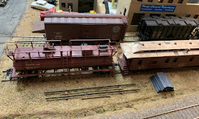
That’s an Albrae Models SP water car just above the rail rack. These models were imported in the light gray color SP used for maintenance equipment after 1959, but since I model 1953, I repainted it boxcar red and relettered. I commented on the model and its prototypes in an earlier post (it’s at: https://modelingthesp.blogspot.com/2018/04/a-southern-pacific-fire-service-car.html ).
     I also built and installed some facilities for track cars, such as speeders, to get off the rails (SP called these “turnouts”), and there too, I used prototype drawings to design and build them. (My post about the modeling is here: https://modelingthesp.blogspot.com/2019/01/track-car-turnouts-part-4-installation.html ., and that post has the link to the prototype drawings too.)  One turnout not shown earlier is just outside the mainline tunnel on my layout (a common location for these turnouts on the prototype, for obvious reasons). Here it is, with the tunnel just out of view at right:


     One more change that I think helps appearances is the extension of the drapes that hang under the layout, below the fascia. I have expressed earlier my belief that black is the best color for drapes, because of the theatrical truism that black is invisible (if you’re interested you can find that post at: https://modelingthesp.blogspot.com/2018/07/thoughts-on-black.html ).
     Using the black layout drapes from when the layout was in Pittsburgh, PA had not covered all the areas I wanted to cover in the present layout, though I had additional old drape sections not needed in the current size of my layout. My wife was kind enough to lengthen the drapes in use, with the material from the old drapes. I already showed in a previous post that one end of my draped area was extended to cover a wide area (here is a link to that description: https://modelingthesp.blogspot.com/2018/09/additional-layout-improvements.html ).
     I also wanted to deal with the area under my layout town of Shumala. The photo below shows the area with the old drape. Note that it ends before the end of the fascia at right (and note how the black simply reads as emptiness). Not obvious is that there is a large opening into the area beneath the layout, between the bookshelves and the fascia, and this of course permits viewing the various kinds of “stuff” stored under there. I would prefer to conceal that opening.


With the drape extension completed, not only was some of the shelving covered, along with that opening into the sub-layout area, but the drape now formed a continuous line around past the end of the fascia, as I had wanted. I think this is a distinctly more finished look.


     These small embellishments to the layout are welcome, and show the value of pursuing small  project along with big ones. I try to keep an open mind whenever I take as step back to evaluate the layout, and see if there are more of these improvements that can be done.
Tony Thompson

Friday, March 8, 2019

Union Oil gas station, Part 5

I have been posting a series of descriptions of my work in modifying and detailing the excellent City Classics kit for a “Moderne” gas station. These were clad with enameled steel panels, so sometimes called the “icebox” style. The most recent post, in which I completed the interior of the station office, can be found at this link: https://modelingthesp.blogspot.com/2019/02/union-oil-gas-station-part-4.html . Having applied the dark gray roof without cement, and having added some details from the kit to the outside of the building, I wanted to try a test fit to my concrete pad with driveways, as I described earlier (see: http://modelingthesp.blogspot.com/2018/09/union-oil-gas-station-part-3.html ).


The location here is at the corner of Pismo Dunes Road and Alder Street in my town of Shumala.
     In the photo above, the island with gas pumps is obviously missing, as is major signage identifying the station as Union 76. My first challenge was the gas pumps. These are provided in the kit as matching halves, which are cemented together and the seam cleaned up. Next comes the challenge of adding gas hoses. Slender black wire is provided in the kit for hoses, but I was disappointed in my ability to get it to assume a relaxed loop of a hose not in use. I decided to use No. 24 wire with black insulation, though this is probably too thick for 1950s hose, and No. 26 or 28 might be better.
     I began by drilling oversize holes at the top hose connection, and at the bottom where the nozzle would be. I used a No. 70 drill, which made it easy later to fit the hose pieces. I drilled a very short distance into the pump body perpendicular to the surface, then changed the drill angle and drilled upwards at about 30 degrees to the surface. I then cut some lengths of wire and experimented to get the hose shape I wanted.
     Next I painted the pump bodies dark blue partway up each side, in accord with Union Oil practice in this era (see a color photo example in my first post in this series: http://modelingthesp.blogspot.com/2015/12/modeling-gas-station.html ). A detail of this photo is repeated below to show the goal.


      I also painted the hose attachment parts of the gas pump a silver color. The painting was followed by gluing on the “meter” faces for the pumps, supplied in the kit, using canopy glue, and also adding small “76” emblems as can be seen in the image above. Finally, the formed hoses were attached with canopy glue. Here is the result. The hoses look oversize here, but are less evident in the completed model.


This permitted me to proceed with the gas pump island. For the light support, I used brass rod instead of the styrene rod supplied in the kit, painted it white, and installed it and the light shade, and painted the base “aged concrete” and the light shade dark green. Along with the stand holding cans of oil, painted in Union orange or blue, it looked like this:


I also added a “Union Oil Service” legend, lifted directly from an on-line photo of a Union station, and glued it in place on the orange stripe of my station building. Note also the soft drink machine and the displayed tire, plus a stack of canned products in the office window. (You can click on the image to enlarge it if you wish.)


     Progress is good on this project, and I should be able to wrap it up with just a little more work. I can then people the scene, add vehicles, and of course a major sign with the “76” logo. I will report on that in a concluding post.
Tony Thompson

Tuesday, March 5, 2019

Putting my Track 7 into service

The last segment of track to be put into service on my layout is the “back track” in my layout town of Ballard, labeled in maps as Track 7. It has been some time since I showed a map of Ballard as it now is, so I include one below. I should mention that this track plan was derived with little change from a town on Terry Walsh’s layout, as I described in a post last year (that can be found at: https://modelingthesp.blogspot.com/2018/06/my-ballard-track-arrangement.html ). You can click on the image to enlarge it if you wish.


Track 7 is the uppermost track in this map, and has four industries along it.
     The first step in being able to use this track was to power the turnout that leads to it, because the turnout is not readily accessible for a hand-throw device (I showed the installation of the necessary switch machine earlier, at: https://modelingthesp.blogspot.com/2019/02/powering-turnouts.html ).
     With that switch machine installed and working, I proceeded to get the track spiked down and electrical feeders installed. I then prepared a first segment of this track for service, reaching to the nearest industry on the track. I showed that feature in a post about a recent operating session (see that post at: https://modelingthesp.blogspot.com/2019/02/a-dress-rehearsal-op-session.html ).
     What the photo in the post just cited did not show was that most of the Code 70 track remained un-leveled and unballasted. A slightly different photo angle makes this obvious:


The large facility of Jupiter Pump and Compressor is at right, with the brass foundry in the center, and Santa Maria Tool & Machine is in the Quonset hut beyond it (modified from a Tru-Scale kit!). 
    An immediate need was to level the track over a somewhat uneven landscape beneath it, and get it ballasted. I usually use scrap ties under whichever edge is low, and can quickly and easily file down the thickness of such a tie to get the right height. A small spirit level is essential here. Once the track is level across the rails, even if somewhat undulating along its length (it’s an industrial spur, after all), I apply some matte medium to the spacers to help glue them down before ballasting.
     The track shown above, ballasted only as far as the foundry, next had its leveling completed for the full length, and then was ballasted to the end. Here is a view in the spirit of the one above, looking along the track, past the Quonset hut. In the middle distance is California Airframe Parts, in the form of a flat that I described a few years back, taken from an actual building near the Oakland Airport (that post is here: https://modelingthesp.blogspot.com/2014/07/making-building-flat-from-prototype.html ). 


A track bumper was installed at the end of track (just visible above), using an Alexander Scale Models #511 Hayes bumper, before completing the ballast.
     The view above has an angle that may be misleading. Below is a more overhead perspective, though this particular view is not available from the layout aisle without something to stand on. The greenish-gray building at left is the kitbashed “semi-flat” that I constructed when my layout was in Pittsburgh, and I described my approach to its construction in a post some years ago (you can read it at: https://modelingthesp.blogspot.com/2013/03/kitbashing-background-structure.html ).


You can see that there is a stub of pavement extending off the main road (Bromela Road), and this stub will be extended across the track. The road surface will have to be adjusted so the road crosses the track at grade (at the moment the track is well above the road), but that’s a subject beyond getting this track into service.
     I am pleased to finally be able to use my Track 7 and to be able to switch its industries. Several of the structures need loading docks, and obviously the area is unscenicked outside of the track, but those are separate topics. For now, I am enjoying being able to operate on this part of the layout.
Tony Thompson

Saturday, March 2, 2019

How were SP branch lines operated?

I am interested in how branch lines were operated (my personal era being the transition era), because my layout is predominantly a Southern Pacific branch off the Coast Division main line. There isn’t much traffic on the branch, so it is served by one or two local trains a day. It does not have any scheduled trains, in common with most SP branches, as shown in division timetables.
     Recently an acquaintance (who shall remain nameless) said to me in a firm voice, “SP branches were operated under yard limit rules.” That means Rule 93. I was surprised at the generalization in the statement, but realized I didn’t know whether it was true for any branch lines, or true for some, or true for all. I first thought to check my 1955-edition SP rule book, and it simply gives a pretty standard version of Rule 93. There is no mention of branch lines. Here is the rule book statement:


     This is subject to Rule 81 or Rule 513, which are similar rules; Rule 513 is for operation in Automatic Block Signal territory. Rule 81 is the foundation of train movement rules. You can see below that it is the first rule in that section of the rule book.


     As I suspected from the start, the operation of branch lines would be spelled out, not in the rule book for the entire railroad, but separately for each division. And this might or might not be included in employee timetables for a particular division, but would certainly be included, if in force, in division Special Instructions publications. Here is an example of one of these, dated 1953, which were (as I understand it) issued in concert with new timetables, but only whenever revisions were made.


     Looking through lots of these for SP Pacific Lines divisions, my conclusion is that although a number of SP branches were indeed operated under yard limits, most were not, including some pretty long ones and a few rather short ones. (For example, the Kentucky House, Friant, Schellville, Oakdale and Ione branches, all quite long, were not in yard limits.) But although yard limits for each subdivision are spelled out in the Special Instructions only, they are always visible also in the timetable. Here is an example from Coast Division, the San Bruno Branch.


This branch left the main line essentially at San Francisco Yard (usually called Bayshore) and was entirely in yard limits; note along the left edge of the timetable that the yard limits are shown.
     Some well-known and busy branches were also operated under yard limits, such as the Arvin Branch. Like San Bruno, it was very near a major yard (Bakersfield), and here is its timetable listing.


Here again, the extreme left edge of the timetable shows the extent of yard limits. 
     So anyone with access to an employee timetable can readily determine which, if any, branches on a particular division were operated under yard limit rules, in the way shown above. But the Special Instructions also indicate all yard limits on each subdivision, under a Rule 93 heading. For the Guadalupe Subdivision of Coast Division, within which my layout is situated, here is the listing:


Note that the Lompoc Branch is listed, but that only 0.35 miles of the branch beyond its mainline junction at Surf is indicated. This of course permits switching at Surf and use of the branch switch, without entering the branch outside yard limit rules.
     I conclude that my mythical Santa Rosalia Branch would likely not have been operated under yard limit rules, and train orders and clearances need to be issued to branchline trains for authority to operate. I do have SP-origin forms for both clearance cards and for train orders (see my description at: https://modelingthesp.blogspot.com/2012/09/modeling-sp-train-orders.html ), so am ready to proceed.
Tony Thompson