I have been putting off building an AL&W Lines kit for a Southern Pacific power house (kit no. SP 21), until I was sure it would fit where I have a kind of blank place on the layout. That space has been occupied for awhile by a cardboard model of a house with a green roof, one that I bought at a swap meet years ago (for more about improvement of this area, see the earlier post: https://modelingthesp.blogspot.com/2020/02/completing-jupiter-pump-compressor.html ). As that post explains, the area is now prepared for a new structure. Here’s a repeat of the original area view.
This AL&W structure kit is for a building roughly 4 by 6 inches in footprint, and of a simple design, though with lots of window and large doors. Below is a photo of a finished kit (built and photographed by Bill Baker), to show what will be completed. It is in the usual SP paint scheme for such structures, of boxcar red walls, black trim, and white window frames and mullions.
The kit has laser-cut styrene walls (Evergreen corrugated) and a variety of peel-and-stick wood detail and trim pieces. I began by choosing the paint scheme for the building (which will not be presented as an SP building), with brown walls and black trim. I chose Tamiya “NATO Brown” (TS-62) for the brown, and used a flat black for all the trim parts.
The recommended first kit assembly step is to assemble the walls to the floor. I chose instead to assemble the walls to each other, using a piece of 1/8-inch square styrene inside each corner. Once the four walls were assembled, I also stiffened the walls with a strip of 1/8 x 1/4-inch styrene above or below the doors and windows. You can see these internal additions below, along with the exterior color.
Next came application of the peel-stick windows and doors, and their frames, and the corner trim. This brings the building sides to a pretty complete look. Note also how different this version of the kit looks, compared to the “official kit photo” above, with its white SP window treatment.
As I mentioned, I chose not to use the floor provided in the kit at this point. I like to leave either the floor area or a separate roof on structures so that if I want to go back and add interior detail or lights, it will be easy to do so.
At this point I added some weathering to the structure, largely a dark gray Pan Pastel vertical streaking in a few areas, and small streaks below the corners of window sills. I went ahead with the kit sequence and added glazing at this point. It is kind of a fussy job to get the clear plastic aligned perfectly with the backs of window assemblies, but if one is off a small amount, decal scissors can be used to remove whatever sticks out. You will not be able to re-insert window assemblies with projecting glazing.
The last step in this first phase is to attach the sub-roof pieces (called “Roof Backing” in the kit). I chose to use canopy glue for this, an excellent adhesive for dissimilar materials (in this case, the styrene walls and plywood sub-roof). I attached each half separately, using small weights to keep them in place.
On the wall segments at left, you can see the “tabs” that fit into slots in the roof pieces (you can click on the image to enlarge it if you wish). Making sure that each of these is engaged in the corresponding slots in the sub-roof ensures that the building will be square.
The concluding steps are to attach the cupola and the outer roof surfaces. I will return to this project in a future post.
Tony Thompson
Friday, February 28, 2020
Tuesday, February 25, 2020
PrairieRail 2020
One of the big operating weekends in the calendar is the biennial PrairieRail event held in Kansas City in even-numbered years. It’s not only big in the sense that Kansas City is one of the hotbeds nationally of model railroading, but also big in the sense that with so many excellent layouts, they can host over 100 operators, more than most such events. I’ve just returned from this year’s get-together.
The usual schedule is four operating sessions, Friday afternoon, two on Saturday, and Sunday morning. With a group of Westerners, I was able to participate in two additional sessions, Thursday night and Friday morning. I won’t attempt to document all the layouts here, and in any event, many excellent operating layouts are not visually striking. But I want to show a few highlights, and mention others.
Certainly one of the most visually stunning layouts was Jim Eudaly’s Hinton Division of the C&O in O scale. Located in a large purpose-built structure, it is remarkably complete and really repays photography. Perhaps more important, it operated flawlessly everywhere I saw. My job was as one of two hostlers at Hinton, a very busy job since every steam-powered train changed power here, many of them double-headers. We two hostlers were occupied every moment! Here is a view of the coal dock and service tracks, where locomotives rarely stood still for long.
Another visually impressive layout was Doug Taylor’s East Broad Top, in HOn3. (He also has a rather large standard-gauge layout in the same basement, the Pennsylvania from Altoona to Pittsburgh (!), but my session was on the EBT.) My job was yardmaster at Mt. Union, the interchange between the PRR and EBT, thus with lots of dual-gauge track. Here is Doug’s rendition of the famous transfer crane, by which narrow-gauge trucks were fitted to standard-gauge cars so they could be moved over the EBT.
Another fine piece of modeling on this EBT layout is the famous EBT shops complex at Orbisonia. Still preserved, the prototype buildings are a remarkable peek into the 19th century, the interiors looking today much as if the workmen had just put down tools and gone to lunch. Doug’s model is excellent.
I don’t want to exclude mention of the really good operating layouts I experienced, from Kevin Leyerle’s OKT portion of the MKT, and Mark Steenwyk’s Milwaukee Beer Line (at the latter, I had the pleasure of using a ProtoThrottle; see: https://www.iascaled.com/store/ProtoThrottle ). I had been to both layouts before, and again greatly enjoyed them both.
A further layout of special note for me was Bob Willer’s Spokane, Portland and Seattle, a superb layout for timetable and train order (T&TO) operation, something I greatly enjoy, and a layout on which I’ve wanted to operate for years. And now I’ve been there, and it was great!
The last layout I operated on was Joe Kasper’s immense Marais Division of the BN, an N-scale layout that operated absolutely perfectly. My job was the Elevator Yard, located across from the main Murray Yard, and from my operating aisle, this was the view into that remarkably large yard. And as you might expect, all three Murray Yard personnel were pretty busy, for the whole session, not that I had much time to watch, with my own busy workload. And there is far more to the layout than this one view can show.
This was a great event, as it has been in past years, and there are still all kinds of layouts in Kansas City I have not been to. I guess I will have to keep on going to PrairieRail and discovering more of these great examples of model railroad accomplishment.
Tony Thompson
The usual schedule is four operating sessions, Friday afternoon, two on Saturday, and Sunday morning. With a group of Westerners, I was able to participate in two additional sessions, Thursday night and Friday morning. I won’t attempt to document all the layouts here, and in any event, many excellent operating layouts are not visually striking. But I want to show a few highlights, and mention others.
Certainly one of the most visually stunning layouts was Jim Eudaly’s Hinton Division of the C&O in O scale. Located in a large purpose-built structure, it is remarkably complete and really repays photography. Perhaps more important, it operated flawlessly everywhere I saw. My job was as one of two hostlers at Hinton, a very busy job since every steam-powered train changed power here, many of them double-headers. We two hostlers were occupied every moment! Here is a view of the coal dock and service tracks, where locomotives rarely stood still for long.
Another visually impressive layout was Doug Taylor’s East Broad Top, in HOn3. (He also has a rather large standard-gauge layout in the same basement, the Pennsylvania from Altoona to Pittsburgh (!), but my session was on the EBT.) My job was yardmaster at Mt. Union, the interchange between the PRR and EBT, thus with lots of dual-gauge track. Here is Doug’s rendition of the famous transfer crane, by which narrow-gauge trucks were fitted to standard-gauge cars so they could be moved over the EBT.
Another fine piece of modeling on this EBT layout is the famous EBT shops complex at Orbisonia. Still preserved, the prototype buildings are a remarkable peek into the 19th century, the interiors looking today much as if the workmen had just put down tools and gone to lunch. Doug’s model is excellent.
I don’t want to exclude mention of the really good operating layouts I experienced, from Kevin Leyerle’s OKT portion of the MKT, and Mark Steenwyk’s Milwaukee Beer Line (at the latter, I had the pleasure of using a ProtoThrottle; see: https://www.iascaled.com/store/ProtoThrottle ). I had been to both layouts before, and again greatly enjoyed them both.
A further layout of special note for me was Bob Willer’s Spokane, Portland and Seattle, a superb layout for timetable and train order (T&TO) operation, something I greatly enjoy, and a layout on which I’ve wanted to operate for years. And now I’ve been there, and it was great!
The last layout I operated on was Joe Kasper’s immense Marais Division of the BN, an N-scale layout that operated absolutely perfectly. My job was the Elevator Yard, located across from the main Murray Yard, and from my operating aisle, this was the view into that remarkably large yard. And as you might expect, all three Murray Yard personnel were pretty busy, for the whole session, not that I had much time to watch, with my own busy workload. And there is far more to the layout than this one view can show.
This was a great event, as it has been in past years, and there are still all kinds of layouts in Kansas City I have not been to. I guess I will have to keep on going to PrairieRail and discovering more of these great examples of model railroad accomplishment.
Tony Thompson
Saturday, February 22, 2020
Freight car graffiti, Part 6: more still
This post continues a series on the graffiti topic, and the predecessor posts are readily found by using “freight car graffiti” as the search term in the search box to the right. The most recent in the series is Part 5, about the process of
re-lettering, in which a railroad or lessee worker recreates car initials
and number after they have been obscured by graffiti, which is here: https://modelingthesp.blogspot.com/2020/02/freight-car-graffiti-part-5-relettering.html .
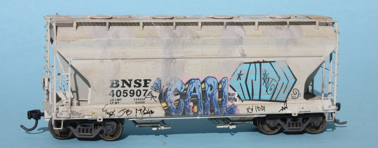
Continuing with the cement cars provided by Seth Neumann (his layout models Union Pacific in the Bay Area in 1999), I began with this BNSF car, an AC&F Center Flow design:
A second car in this series is an older Santa Fe cement hopper, of ribbed-side design, which already had a light haze of weathering:
This car, as an older car with long service, was planned to have heavier cement build-up and staining than the newer Center Flow car. I’ll begin with it. Here is the left side of the car, with a decal from Microscale set 87-1535.
Next is the right side, also using another Microscale decal (set 87-1534) to be able to work over the ribs, which are sharply rectangular on this model.
The other car, with a much newer paint scheme, should be more lightly weathered. But it will still carry graffiti. Here is the left side, with yet another Microscale decal (set 87-1534):
The right side of this model received two decals. At left is one from Blair Line set 2261, at right one from Microscale set 87-1536. This latter set from Microscale might not seem interesting, as it’s named “Irish and Scottish Graffiti,” but many of its contents are quite useful and not really different from American graffiti. I show the car below with some light cement staining. This car is a much later repaint, not long before the 1999 year of the layout for which these cars are intended, so only light staining is shown.
The other side of the car, shown one photo above, has now been similarly weathered.
Of these two cars, the boxcar-red Santa Fe car is obviously much the older paint scheme, so I gave it heavier cement staining. I will say more in a separate post about weathering for cement cars like these, but this car was originally a color which really shows the cement spillage.
These cement cars have been an interesting challenge, both to apply graffiti and also to weather to varying degrees, appropriate to the age of the various paint schemes. It is a continuing project, so I will have more to say in future posts.
Tony Thompson
Continuing with the cement cars provided by Seth Neumann (his layout models Union Pacific in the Bay Area in 1999), I began with this BNSF car, an AC&F Center Flow design:
A second car in this series is an older Santa Fe cement hopper, of ribbed-side design, which already had a light haze of weathering:
This car, as an older car with long service, was planned to have heavier cement build-up and staining than the newer Center Flow car. I’ll begin with it. Here is the left side of the car, with a decal from Microscale set 87-1535.
Next is the right side, also using another Microscale decal (set 87-1534) to be able to work over the ribs, which are sharply rectangular on this model.
The other car, with a much newer paint scheme, should be more lightly weathered. But it will still carry graffiti. Here is the left side, with yet another Microscale decal (set 87-1534):
The right side of this model received two decals. At left is one from Blair Line set 2261, at right one from Microscale set 87-1536. This latter set from Microscale might not seem interesting, as it’s named “Irish and Scottish Graffiti,” but many of its contents are quite useful and not really different from American graffiti. I show the car below with some light cement staining. This car is a much later repaint, not long before the 1999 year of the layout for which these cars are intended, so only light staining is shown.
The other side of the car, shown one photo above, has now been similarly weathered.
Of these two cars, the boxcar-red Santa Fe car is obviously much the older paint scheme, so I gave it heavier cement staining. I will say more in a separate post about weathering for cement cars like these, but this car was originally a color which really shows the cement spillage.
These cement cars have been an interesting challenge, both to apply graffiti and also to weather to varying degrees, appropriate to the age of the various paint schemes. It is a continuing project, so I will have more to say in future posts.
Tony Thompson
Wednesday, February 19, 2020
Completing Jupiter Pump & Compressor
My one concession to a (relatively) large industry on my layout is the company named in the title of this post, Jupiter Pump & Compressor, makers of both water pumps and air compressors. For a description of the starting points for this industry on the layout, you may wish to read this post: https://modelingthesp.blogspot.com/2015/09/jupiter-pump-and-compressor.html .
That first post was followed by some additional work, including adding an identifying sign; see: https://modelingthesp.blogspot.com/2015/10/jupiter-pump-compressor-part-2.html . Later I decided that the plant could have its own switcher for in-plant car movement, and thus the SP local train would not switch the plant, but would only set out and pick up from the plant’s lead track. For all that, see this post: https://modelingthesp.blogspot.com/2015/12/a-plant-switcher-at-jupiter-pump.html
But in front of the plant is a space that has been occupied for awhile by a cardboard model of a house with a green roof, one that I bought at a swap meet years ago. I wouldn’t defend it as more than a space-filling building. It doesn’t even sit flat on the site.
It is definitely time to make something better for this area! Ideally, I have always intended to build one or more structures for this space, that would be a suitable part of the Jupiter facility behind it.
The first step is to level the site and consider what should fill it. I have long imagined a ramp down to the area alongside the corrugated building (at the left of the photo above), and an employee parking area there. Some other structure can then replace that green-roofed model. Accordingly, I started roughly filling the low spots with Sculptamold, then refining contours with a taxidermists’ paper mache, Brandt’s Compound, which I’ve mentioned in a previous post (it’s at: http://modelingthesp.blogspot.com/2012/11/the-shumala-extension.html ).
With a base filler of Sculptamold (white), and the Brandt’s Compound (gray) completing the contour desired, the area looked like this after the rough installation. (Note at the back of the area that there is an opening below the backdrop, just to the right of the brick building flat, something also being fixed in this project.)
Incidentally, this high-angle view (not one that any visitor could have, unless over 7 feet tall), shows that the two tracks into the Jupiter receiving building do not actually connect with the switcher track. But with the building in place, this cannot be seen.
With this rough fill added, I used very coarse sandpaper to smooth off any roughness and obtain a fairly flat surface. Then, as I always do in these projects, I painted all the ground areas a base medium brown, my favorite “ground” color, Rust-Oleum “Nutmeg.”
Obviously dirt and vegetation are needed, along with an indication that this is a roadway into the area, but that is straightforward work. I’ll summarize it later.
Another piece of work needing to be done was to apply a backing of foam-core board to the lower Jupiter building at the right of the tall plant structure (see top photo in this post). I also added a cut-out outline of some trees behind the building, to help hide the gap I mentioned. This simply sits in place at the back. Here you see the buildings all in place.
This completes some of the background area work that was needed, but there is more, as I will describe presently.
Lastly, I have chosen a new structure to build and put into place instead of the house with the green roof (though in about the same place). I will return to that in a future post also.
Tony Thompson
That first post was followed by some additional work, including adding an identifying sign; see: https://modelingthesp.blogspot.com/2015/10/jupiter-pump-compressor-part-2.html . Later I decided that the plant could have its own switcher for in-plant car movement, and thus the SP local train would not switch the plant, but would only set out and pick up from the plant’s lead track. For all that, see this post: https://modelingthesp.blogspot.com/2015/12/a-plant-switcher-at-jupiter-pump.html
But in front of the plant is a space that has been occupied for awhile by a cardboard model of a house with a green roof, one that I bought at a swap meet years ago. I wouldn’t defend it as more than a space-filling building. It doesn’t even sit flat on the site.
It is definitely time to make something better for this area! Ideally, I have always intended to build one or more structures for this space, that would be a suitable part of the Jupiter facility behind it.
The first step is to level the site and consider what should fill it. I have long imagined a ramp down to the area alongside the corrugated building (at the left of the photo above), and an employee parking area there. Some other structure can then replace that green-roofed model. Accordingly, I started roughly filling the low spots with Sculptamold, then refining contours with a taxidermists’ paper mache, Brandt’s Compound, which I’ve mentioned in a previous post (it’s at: http://modelingthesp.blogspot.com/2012/11/the-shumala-extension.html ).
With a base filler of Sculptamold (white), and the Brandt’s Compound (gray) completing the contour desired, the area looked like this after the rough installation. (Note at the back of the area that there is an opening below the backdrop, just to the right of the brick building flat, something also being fixed in this project.)
Incidentally, this high-angle view (not one that any visitor could have, unless over 7 feet tall), shows that the two tracks into the Jupiter receiving building do not actually connect with the switcher track. But with the building in place, this cannot be seen.
With this rough fill added, I used very coarse sandpaper to smooth off any roughness and obtain a fairly flat surface. Then, as I always do in these projects, I painted all the ground areas a base medium brown, my favorite “ground” color, Rust-Oleum “Nutmeg.”
Obviously dirt and vegetation are needed, along with an indication that this is a roadway into the area, but that is straightforward work. I’ll summarize it later.
Another piece of work needing to be done was to apply a backing of foam-core board to the lower Jupiter building at the right of the tall plant structure (see top photo in this post). I also added a cut-out outline of some trees behind the building, to help hide the gap I mentioned. This simply sits in place at the back. Here you see the buildings all in place.
This completes some of the background area work that was needed, but there is more, as I will describe presently.
Lastly, I have chosen a new structure to build and put into place instead of the house with the green roof (though in about the same place). I will return to that in a future post also.
Tony Thompson
Sunday, February 16, 2020
Freight car graffiti, Part 5: relettering
I began my descriptions of graffiti applications on “modern” freight cars with an article in Model Railroad Hobbyist or MRH, and my post linking to that article, including a brief description of my method of paper overlays for graffiti, is at this link: https://modelingthesp.blogspot.com/2020/01/my-latest-column-in-mrh.html . I followed that up with a description of a few additional examples of graffiti applications to models, in this post: https://modelingthesp.blogspot.com/2020/01/freight-car-graffiti-part-2.html .
That was followed by two sets of additional examples, continuing to show mixtures of graffiti decals, and my paper overlays, parts 3 and 4. Any of these can be found by using “freight car graffiti” as the search term in the search box at upper right.
I have continued to work on the representation of graffiti for post-1980 freight car appearance. My primary reference in doing so is the excellent book, Freight Train Graffiti, by Roger Gastman, Darin Rowland, and Ian Sattler (Abrams Books, New York, 2006). It’s a 7 x 8-inch book of 350 pages, and contains over 1000 illustrations of graffiti applications.
The book remains readily available from on-line sellers of new and used books.
I continue to photograph prototype graffiti, on both freight cars and buildings, as candidates for the paper overlay technique I described in the MRH article and in my post about the article (link provided in the first paragraph of the present post). I have also harvested more images from the Freight Train Graffiti book (above), as I showed in the MRH article.
In the present post, I want to talk about “relettering,” by which I mean the re-creation of a freight car’s reporting marks, car number, capacity data, or COTS boxes, by railroads or car lessees, after such lettering has been obscured by graffiti applications. I have seen examples myself, and there are good illustrations in the book I have cited in both the preceding posts, Freight Train Graffiti, or FTG.
I will use a couple of pairs of photos from the book to illustrate. The first one is an example of the graffiti having carefully avoided the reporting marks and car number of a BAR car, but covering the capacity data with the word “cycle.” A panel was painted over the graffiti to permit restenciling the required data (from FTG, page 262).
Another example of the graffiti obscuring lettering, this time covering all the lettering on the left of the Fruit Growers car side (it’s the word “krash”), which then got a new panel so all the obscured marks and data could be repainted (from FTG, page 263).
This kind of relettering is common enough, and of course understandable, for a wide range of types of repainting. Here’s another example of all the reporting mark-car number-capacity data being replaced, this time on two paint patches (from FTG, page 275):
On one of the recent 1999 freight cars to which I was applying graffiti and weathering, a blue Atlas model of a 5700-cubic-foot car marked for Arco Polymers Inc., I decided to add a paint patch of relettering. Shown below is one side of this model, where you can see that I avoided applying graffiti over the car initials and number (the large graffiti application at right is a paper overlay, using an image from FTG, page 210). This car was also described in Part 3: https://modelingthesp.blogspot.com/2020/01/freight-car-graffiti-part-3-more.html .
On the other side, I deliberately applied a graffiti decal (from Microscale set 87-1536) so that it obscured part of the car initials and number. I then applied a rectangle of black decal, and used a “stencil” style lettering alphabet to replace those reporting marks. Below is the entire car, and at the right end of the car side is a paper overlay of the word “sicko,” another image from FTG, page 238.
Here is an enlargement of the replaced reporting marks.
This kind of relettering over or around graffiti is moderately common on prototype freight cars that have received graffiti. I will be exploring more examples of this detail in future posts.
Tony Thompson
That was followed by two sets of additional examples, continuing to show mixtures of graffiti decals, and my paper overlays, parts 3 and 4. Any of these can be found by using “freight car graffiti” as the search term in the search box at upper right.
I have continued to work on the representation of graffiti for post-1980 freight car appearance. My primary reference in doing so is the excellent book, Freight Train Graffiti, by Roger Gastman, Darin Rowland, and Ian Sattler (Abrams Books, New York, 2006). It’s a 7 x 8-inch book of 350 pages, and contains over 1000 illustrations of graffiti applications.
The book remains readily available from on-line sellers of new and used books.
I continue to photograph prototype graffiti, on both freight cars and buildings, as candidates for the paper overlay technique I described in the MRH article and in my post about the article (link provided in the first paragraph of the present post). I have also harvested more images from the Freight Train Graffiti book (above), as I showed in the MRH article.
In the present post, I want to talk about “relettering,” by which I mean the re-creation of a freight car’s reporting marks, car number, capacity data, or COTS boxes, by railroads or car lessees, after such lettering has been obscured by graffiti applications. I have seen examples myself, and there are good illustrations in the book I have cited in both the preceding posts, Freight Train Graffiti, or FTG.
I will use a couple of pairs of photos from the book to illustrate. The first one is an example of the graffiti having carefully avoided the reporting marks and car number of a BAR car, but covering the capacity data with the word “cycle.” A panel was painted over the graffiti to permit restenciling the required data (from FTG, page 262).
Another example of the graffiti obscuring lettering, this time covering all the lettering on the left of the Fruit Growers car side (it’s the word “krash”), which then got a new panel so all the obscured marks and data could be repainted (from FTG, page 263).
This kind of relettering is common enough, and of course understandable, for a wide range of types of repainting. Here’s another example of all the reporting mark-car number-capacity data being replaced, this time on two paint patches (from FTG, page 275):
On one of the recent 1999 freight cars to which I was applying graffiti and weathering, a blue Atlas model of a 5700-cubic-foot car marked for Arco Polymers Inc., I decided to add a paint patch of relettering. Shown below is one side of this model, where you can see that I avoided applying graffiti over the car initials and number (the large graffiti application at right is a paper overlay, using an image from FTG, page 210). This car was also described in Part 3: https://modelingthesp.blogspot.com/2020/01/freight-car-graffiti-part-3-more.html .
On the other side, I deliberately applied a graffiti decal (from Microscale set 87-1536) so that it obscured part of the car initials and number. I then applied a rectangle of black decal, and used a “stencil” style lettering alphabet to replace those reporting marks. Below is the entire car, and at the right end of the car side is a paper overlay of the word “sicko,” another image from FTG, page 238.
Here is an enlargement of the replaced reporting marks.
This kind of relettering over or around graffiti is moderately common on prototype freight cars that have received graffiti. I will be exploring more examples of this detail in future posts.
Tony Thompson
Thursday, February 13, 2020
Starting prep for ProRail
The annual national operating weekend, called ProRail, is going to return to the San Francisco Bay Area in April ( to learn more about this event, visit http://www.bayrails.com/index.php ), and I have volunteered to have my layout included for operating sessions. Accordingly, I am not only working on getting a bunch of layout projects finished, but am aiming at refinement and polishing of the operating scheme on my layout.
Among the work already done is the refreshing of scenic materials in areas that get wear during operating sessions, mostly along layout edges at the aisles, and in a few areas of older scenery that have gotten a little faded or dusty. In addition, industry structures are being checked for completeness, and things like window shades not previously completed have been added. Lastly, a few changes in operating scheme patterns have been modified with an aim to optimize how everything works.
To that end, I hosted operating sessions on February 8 and 9, the latter being the 52nd session on the layout in its present form. I will just show a couple of shots of crews operating. Below you see Bill Kaufman (at left) and Seth Neumann working at Shumala. Seth was the engineer at this point, and the conductor, Bill, is directing the next move, evidently to spot a car at the ice deck for initial icing.
While those two were at work, on the other side of the layout in the town of Ballard, Jim Providenza (at left) and Clifton Linton were getting ready to switch. Jim was the conductor here and you can see that his train orders are in his shirt pocket. He’s working on a switch list for the work to be done in Ballard. Clif was the engineer and is holding a throttle.
I have also done a fresh version of my “walking around” list of things that need to be done, large and small, for the entire layout (a previous post about this process is here: https://modelingthesp.blogspot.com/2018/07/management-by-walking-around.html ).
In addition to this effort, I am experimenting with a variety of switching and train moves, to evaluate possible changes in the operating pattern that is in current use. I usually run through the expected moves that are needed to implement any changes, to make sure that I like each change. The high-angle view of Shumala below shows an example.
I certainly intend that these efforts will bring me closer to being ready for ProRail. I want the layout to be at its best for whatever state of completion exists at the time of the event.
Tony Thompson
Among the work already done is the refreshing of scenic materials in areas that get wear during operating sessions, mostly along layout edges at the aisles, and in a few areas of older scenery that have gotten a little faded or dusty. In addition, industry structures are being checked for completeness, and things like window shades not previously completed have been added. Lastly, a few changes in operating scheme patterns have been modified with an aim to optimize how everything works.
To that end, I hosted operating sessions on February 8 and 9, the latter being the 52nd session on the layout in its present form. I will just show a couple of shots of crews operating. Below you see Bill Kaufman (at left) and Seth Neumann working at Shumala. Seth was the engineer at this point, and the conductor, Bill, is directing the next move, evidently to spot a car at the ice deck for initial icing.
While those two were at work, on the other side of the layout in the town of Ballard, Jim Providenza (at left) and Clifton Linton were getting ready to switch. Jim was the conductor here and you can see that his train orders are in his shirt pocket. He’s working on a switch list for the work to be done in Ballard. Clif was the engineer and is holding a throttle.
I have also done a fresh version of my “walking around” list of things that need to be done, large and small, for the entire layout (a previous post about this process is here: https://modelingthesp.blogspot.com/2018/07/management-by-walking-around.html ).
In addition to this effort, I am experimenting with a variety of switching and train moves, to evaluate possible changes in the operating pattern that is in current use. I usually run through the expected moves that are needed to implement any changes, to make sure that I like each change. The high-angle view of Shumala below shows an example.
I certainly intend that these efforts will bring me closer to being ready for ProRail. I want the layout to be at its best for whatever state of completion exists at the time of the event.
Tony Thompson
Monday, February 10, 2020
Modeling SP whistle posts
I provided the prototype background on Southern Pacific whistle post design(s) over the years in an earlier post, from last December, which can be viewed here: https://modelingthesp.blogspot.com/2019/12/southern-pacifics-whistle-post.html . Now I want to address modeling.
Since I model 1953, I want to use the single-board design in force in those years, as shown in one of the photos in the post just cited. The letter “X” on the post is about 8 inches wide, and a suitable post would be a 12-inch wide board. This is quite easy to do in HO scale, using Evergreen styrene strip of 2 x 12-inch scale size.
I had some concern that during layout operation, a styrene post this thin would be pretty vulnerable to careless elbows, etc. One approach to that issue would be to realize that since the model post is very simple to build, one could merely make a whole bunch of styrene posts and replace whenever necessary. But some locations are vulnerable enough that I decided to make some posts out of brass.
I decided to go ahead and use the actual letter “X” from the later SP drawing, CS-1360, that was shown in the previous post on this topic (first paragraph above). It is interesting that it is slightly asymmetrical, with the part above the crossing of the two strokes slightly higher than the bottom part. Well, that is what SP did. Here is a view of it:
For my HO posts, this graphic is simply reduced to fit the model post, printed out on paper, and glued to the post, whether styrene or brass, using canopy glue.
I made one brass post by sawing a scale 12-inch wide strip out of 0.032-inch thickness brass sheet, but it is easier to use commercial 1/8-inch wide brass strip. In HO scale, this is close to 11 inches wide. The strip I purchased is 24 gauge red brass (15 percent zinc instead of the 30 percent found in yellow brass). Sheet of 24 gauge is 0,0239 inches thick, or in HO scale, very close to 2 inches. This is pretty suitable for modeling a 2 x 12-inch post in HO.
Shown below are a styrene post (with its back side already painted brown, as the prototype did) and below, a brass post, somewhat shorter. Both are long enough that they can meet the SP specification that the post top should stand 6 feet above the ground.
I have at least one well-protected location where a styrene post will probably survive, so made up one for that location and installed it. The cliff alongside this location should mean that careless elbows will not wander into this area. As the prototype drawing specifies (see that drawing in the post cited in the first paragraph of the present post), the location is 13 scale feet from the track centerline, and is in the ballast shoulder, not down in the ditch.
To illustrate a more exposed location, the view below shows one that is close to the layout edge along the aisle, at right. Here I installed a brass post. We will see how this one does in service!
In most operating sessions on my layout, crews usually do whistle for crossings, and I am glad to provide them a reminder to do so, in the form of a prototype post.
Tony Thompson
Since I model 1953, I want to use the single-board design in force in those years, as shown in one of the photos in the post just cited. The letter “X” on the post is about 8 inches wide, and a suitable post would be a 12-inch wide board. This is quite easy to do in HO scale, using Evergreen styrene strip of 2 x 12-inch scale size.
I had some concern that during layout operation, a styrene post this thin would be pretty vulnerable to careless elbows, etc. One approach to that issue would be to realize that since the model post is very simple to build, one could merely make a whole bunch of styrene posts and replace whenever necessary. But some locations are vulnerable enough that I decided to make some posts out of brass.
I decided to go ahead and use the actual letter “X” from the later SP drawing, CS-1360, that was shown in the previous post on this topic (first paragraph above). It is interesting that it is slightly asymmetrical, with the part above the crossing of the two strokes slightly higher than the bottom part. Well, that is what SP did. Here is a view of it:
For my HO posts, this graphic is simply reduced to fit the model post, printed out on paper, and glued to the post, whether styrene or brass, using canopy glue.
I made one brass post by sawing a scale 12-inch wide strip out of 0.032-inch thickness brass sheet, but it is easier to use commercial 1/8-inch wide brass strip. In HO scale, this is close to 11 inches wide. The strip I purchased is 24 gauge red brass (15 percent zinc instead of the 30 percent found in yellow brass). Sheet of 24 gauge is 0,0239 inches thick, or in HO scale, very close to 2 inches. This is pretty suitable for modeling a 2 x 12-inch post in HO.
Shown below are a styrene post (with its back side already painted brown, as the prototype did) and below, a brass post, somewhat shorter. Both are long enough that they can meet the SP specification that the post top should stand 6 feet above the ground.
I have at least one well-protected location where a styrene post will probably survive, so made up one for that location and installed it. The cliff alongside this location should mean that careless elbows will not wander into this area. As the prototype drawing specifies (see that drawing in the post cited in the first paragraph of the present post), the location is 13 scale feet from the track centerline, and is in the ballast shoulder, not down in the ditch.
To illustrate a more exposed location, the view below shows one that is close to the layout edge along the aisle, at right. Here I installed a brass post. We will see how this one does in service!
In most operating sessions on my layout, crews usually do whistle for crossings, and I am glad to provide them a reminder to do so, in the form of a prototype post.
Tony Thompson
Subscribe to:
Posts (Atom)