Next week I’ll be at the NMRA National Convention in Sacramento, giving three different clinics (on waybills, SP freight car modeling, and on PFE operations), and participating in other activities, such as the RPM display room. It’s always a good gathering of modelers, and registrations already exceed 1500 (we hope we may get as many as 2000, and have planned for that many).
I’ll be reading e-mail and checking web sites during the week, so I won’t be altogether out of touch. I’ve been asked if I would put up any of my clinic handouts in the form of posts, and I will likely do so after the convention. One possible source of such topics is the National Train Show (NTS), which runs from Friday July 8 through Sunday the 10th. Some manufacturers do show new products at the NTS, so it’s possible there will be some news of that kind.
I will also report anything else which seems to me to be of interest to the topic of this blog, probably while I’m there or as soon as I get back on Sunday, July 10. This could stem from clinics, meetings, or even hallway conversations. That’s part of the attraction of an event like this: the social interactions are a major piece of the event, and an important reason why I’m looking forward to the convention.
Tony Thompson
Thursday, June 30, 2011
Thursday, June 23, 2011
A few words on packing houses and produce shipping
It’s not my intention to offer a great exposition on these subjects, but instead to summarize some of the aspects which affect modeling structures and operations.
First, packing houses varied tremendously and it might even be correct to say that there were no two alike. For an extensive look at such structures, Jim Lancaster’s web site is an excellent resource (see: http://coastdaylight.com/ljames1/scph.html). Most of us model rail-served houses, and these typically had a loading platform trackside of two to five carlengths (sometimes larger). The great majority of packing houses were located near the growing area, so that harvested produce could be brought directly from the fields or orchards to be cleaned and packed at the packing house. This means that one should provide truck unloading capability (if one models that side of the house), even if only in the form of a roadway running behind the structure.
In areas of intense agricultural development, it would not be uncommon to have a dozen packing houses in a single town. Usually this is too many to model, but I mention it because the usual modeler’s choice of a single packing house per town is probably not very realistic in many cases. (Of course, if you are accurately depicting a prototype scene with only a single house, that’s how it should be done.)
For the most part, packing houses did just what the name implies: they packed the produce into shipping containers (which were also point-of-sale containers). Produce certainly would be washed to remove field dirt, to varying degrees of thoroughness, and would have been culled to remove unripe, damaged or spoiled pieces, along with unwanted stems, leaves, etc. Then it was packed into crates, cartons, hampers, lugs, boxes, or whatever was customary for that particular type of produce. In the early 1950s, when I model, cardboard cartons were just coming into use, and wooden crates remained virtually standard.
These containers were sized with two things in mind: the standard sale size for that produce type, and fitting into a standard refrigerator car with minimal or even no dunnage and making a tight fit to ensure no movement during transit. For these reasons, container sizes and proportions varied widely among fruit and vegetable varieties. This is readily seen in a collection of box labels for these products, because normally the label occupied the entire end of a container. There is much more on car loading arrangements in Chapter 14 of the book Pacific Fruit Express (2nd edition, Signature Press, 2000).
Box labels are an entire subject of their own, and a number of fine books have been produced to reproduce and discuss the art and design of such labels. I would recommend any of the following to someone who’d like to look at that side of the subject. All are focused on citrus, mostly oranges.
John Salkin and Laurie Gordon, Orange Crate Art, Warner Books, New York, 1976 (paperback).
Richard H. Barker (editor), Selling the Gold: Citrus Roots . . . Our Legacy, Upland Public Library Foundation, Upland, Calif., 1999 (paperback).
Gordon T. McClelland and Jay T. Last, California Orange Box Labels, Hillcrest Press, Beverly Hills, Calif., 1985 (hardback).
Many of these labels were vivid, sometimes featuring scantily-clad women or sports images, and it should be recalled that these were aimed at male wholesale produce buyers, not at housewives in grocery stores. Many examples were shown in Signor's and my book, Southern Pacific’s Coast Line Pictorial (Signature Press, 2000).
For my own modeling, I want to use actual packing concerns and packing labels from the central coast area. Among them are Phelan & Taylor, a still-standing (though not operating) packing house in Oceano, and Western Packing of Guadalupe. This area, incidentally, is dominated by vegetable shipping. Here are a couple of scans from original labels.


Since my layout town locations are mythical, I will probably modify the labels to reflect my layout town names, for example something like this:

Here’s another example, for my lemon packing house in Santa Rosalia. It has a separate shipping building, as seen here:

I have modified a 1920s lemon label to fit this shipper:

Of course packing crates are pretty small in HO scale, and the name changes just shown are even tinier, but just as one can do automobile license plates, so can one do box labels, and I will be using these, so that a stack of crates with the “right” labels can be waiting on the loading dock.
Tony Thompson
First, packing houses varied tremendously and it might even be correct to say that there were no two alike. For an extensive look at such structures, Jim Lancaster’s web site is an excellent resource (see: http://coastdaylight.com/ljames1/scph.html). Most of us model rail-served houses, and these typically had a loading platform trackside of two to five carlengths (sometimes larger). The great majority of packing houses were located near the growing area, so that harvested produce could be brought directly from the fields or orchards to be cleaned and packed at the packing house. This means that one should provide truck unloading capability (if one models that side of the house), even if only in the form of a roadway running behind the structure.
In areas of intense agricultural development, it would not be uncommon to have a dozen packing houses in a single town. Usually this is too many to model, but I mention it because the usual modeler’s choice of a single packing house per town is probably not very realistic in many cases. (Of course, if you are accurately depicting a prototype scene with only a single house, that’s how it should be done.)
For the most part, packing houses did just what the name implies: they packed the produce into shipping containers (which were also point-of-sale containers). Produce certainly would be washed to remove field dirt, to varying degrees of thoroughness, and would have been culled to remove unripe, damaged or spoiled pieces, along with unwanted stems, leaves, etc. Then it was packed into crates, cartons, hampers, lugs, boxes, or whatever was customary for that particular type of produce. In the early 1950s, when I model, cardboard cartons were just coming into use, and wooden crates remained virtually standard.
These containers were sized with two things in mind: the standard sale size for that produce type, and fitting into a standard refrigerator car with minimal or even no dunnage and making a tight fit to ensure no movement during transit. For these reasons, container sizes and proportions varied widely among fruit and vegetable varieties. This is readily seen in a collection of box labels for these products, because normally the label occupied the entire end of a container. There is much more on car loading arrangements in Chapter 14 of the book Pacific Fruit Express (2nd edition, Signature Press, 2000).
Box labels are an entire subject of their own, and a number of fine books have been produced to reproduce and discuss the art and design of such labels. I would recommend any of the following to someone who’d like to look at that side of the subject. All are focused on citrus, mostly oranges.
John Salkin and Laurie Gordon, Orange Crate Art, Warner Books, New York, 1976 (paperback).
Richard H. Barker (editor), Selling the Gold: Citrus Roots . . . Our Legacy, Upland Public Library Foundation, Upland, Calif., 1999 (paperback).
Gordon T. McClelland and Jay T. Last, California Orange Box Labels, Hillcrest Press, Beverly Hills, Calif., 1985 (hardback).
Many of these labels were vivid, sometimes featuring scantily-clad women or sports images, and it should be recalled that these were aimed at male wholesale produce buyers, not at housewives in grocery stores. Many examples were shown in Signor's and my book, Southern Pacific’s Coast Line Pictorial (Signature Press, 2000).
For my own modeling, I want to use actual packing concerns and packing labels from the central coast area. Among them are Phelan & Taylor, a still-standing (though not operating) packing house in Oceano, and Western Packing of Guadalupe. This area, incidentally, is dominated by vegetable shipping. Here are a couple of scans from original labels.


Here’s another example, for my lemon packing house in Santa Rosalia. It has a separate shipping building, as seen here:

I have modified a 1920s lemon label to fit this shipper:

Of course packing crates are pretty small in HO scale, and the name changes just shown are even tinier, but just as one can do automobile license plates, so can one do box labels, and I will be using these, so that a stack of crates with the “right” labels can be waiting on the loading dock.
Tony Thompson
Monday, June 20, 2011
A small personal note
This blog has been and will continue to be about modeling the SP. But a recent discovery impels me to adding a small personal note.
I still remember the first thing I ever published, which was a rock climbing guide to an area near Boston, created when I was in graduate school and a fairly regular climber. The area is in Quincy, south of the city, and happens to be at the site of one of the very first railroads in America, the Granite Railway, built to haul cut granite from the quarry for the construction of the Bunker Hill Monument in 1826. It had iron rails, supported on small granite blocks (not ties), and was horse powered.
The remnant of that first quarry was later called “Little Railroad Quarry,” and I worked with another experienced climber at the quarries, William (Willie) Crowther, who had written a small guide earlier, created only as a mimeographed text and long out of print. He and I created a new and expanded text, and I made drawings of the cliff areas from photographs, to show the climbing routes. I organized the layout and printing, and it was published in 1968 by the M.I.T. Outing Club, and was reissued in 1970 with a supplement. It was just 5 x 7.5 inches in size, intended of course as a pocket guide.
What brought all this up? I wondered what had happened in the interim. It turns out that Boston’s Metropolitan District Commission has purchased the land and created a public reservation, so climbing continues. And to my surprise, the Wikipedia entry about the area mentions Willie’s and my guidebook (see: http://en.wikipedia.org/wiki/Quincy_Quarries_Reservation).
My next challenge was to find if I could locate a copy amongst my belongings, and despite the passage of years, I succeeded. Here’s the cover:

And remarkably, you can buy this little 24-page booklet through Amazon.com and ABE Books, at staggering prices. (The 1970 reprint is also available; it had a yellow cover.)
Although the railroad connection of this tale is minute, it was a real discovery for me to make this connection to my own past. Hope you don’t mind hearing about it.
Tony Thompson
Choosing a model car fleet, Part 12: box cars
This is the twelfth in a series of posts entitled “Choosing a model car fleet,” and because it will require multiple parts to be presented, I’ve changed the title a bit. The reason to expect multiple parts is simply that box cars were very numerous, the commonest car type on North American railroads in the 1950s. Moreover, western railroads such as SP, UP, WP, Santa Fe, GN, NP, Milwaukee and others all had box car fleets substantially larger (in percentage terms) than the national average.
I plan to present my model car fleet ideas for box cars in at least these parts: the SP cars; cars of other railroads; and “signature” cars of other railroads. For the SP cars, I expect to proportion my model fleet according to the proportions of the SP prototype fleet, as I discussed for PFE cars in my first post on this topic, at: http://modelingthesp.blogspot.com/2010/12/choosing-model-car-fleet.html. A similar idea will be the basis for cars of other railroads, according to the Gilbert-Nelson hypothesis I’ve described previously. (see: http://modelingthesp.blogspot.com/2010/12/choosing-model-car-fleet-2.html) In the present post, I just want to introduce these topics.
The term “signature cars” perhaps deserves some explanation. Modelers and railfans have long recognized distinctive or unique freight cars of certain railroads, cars like the Milwaukee Road ribbed-side box cars, and the Baltimore & Ohio wagon-top cars with their distinctive continuous roof-and-side design. Such cars are icons, and of course I will have examples in my fleet, but by “signature” I mean something different. I mean cars which typified the fleets of their owners, being present in sufficient numbers to form an important part of that fleet, and not being widely used by others. Examples would certainly include the Pennsylvania X29 (and the PRR wagon-top cars), but also cars like the wood-sheathed 1937 AAR box cars of NP and GN; the “Fowler” box cars of D&RGW; the double-sheathed WP box cars; and many others.
The signature cars are in most cases not candidates to be produced in injection-molded styrene, but are natural candidates for resin kit production. This is the avenue I’ve followed for some of these cars, and many desirable cars of this type are available as kits from Westerfield, Speedwitch, and especially Sunshine. I should emphasize that I have chosen these along with the unique or distinctive cars like the B&O wagon-tops, in making up the non-SP part of my model box car fleet.
My approach is still to use a Gilbert-Nelson sense of numerical proportion, but in appropriate cases to choose the signature car, if available, along with the myriad 1937 AAR steel box cars and other standards. Almost any fleet will need plenty of standard cars, but ideally would be leavened with unique and signature car types too.
I’ll just show a single example here, one of the NP double-sheathed box cars in a series that numbered in the thousands. Mike Brock likes to say that one of his rules of freight cars is that every train contains at least one NP box car. I wouldn’t go that far, but he is right that they are often visible (partly because of their distinctive arched road name lettering, allowing them to stand out among otherwise anonymous cars). This model was built by Dennis Williams, but lettering and weathering were done by me. It’s from from Sunshine kit 52.2, modeling the NP 10000–13999 series double-sheathed box cars with corrugated steel ends.

Additional posts on this topic will delve into my SP box car fleet, along with the emerging patterns among the box cars of other railroads which I’m operating.
Tony Thompson
Saturday, June 18, 2011
San Luis Obispo operations-2
I thought it might be interesting to provide more segments from my interview with Malcolm (Mac) Gaddis. Mac worked at San Luis Obispo in the early 1950s, and his recollections are not only interesting in their own right, but are vital chunks of information for anyone modeling the San Luis area or wishing to operate that area prototypically. Previous posts with material from this interview were either entitled “modeling freight traffic,” such as http://modelingthesp.blogspot.com/2011/01/modeling-freight-traffic-coast-line_19.html , with more added under the title “San Luis Obispo operations,” at http://modelingthesp.blogspot.com/2011/05/san-luis-obispo-operations.html.
In this post, I will concentrate on Mac’s remarks about San Luis itself, and about area operations.
I began this part by asking about facilities and locomotive usage, while showing some 8 x 10 prints of San Luis Obispo scenes.
Gaddis: One thing I found, in 1951 or 52, we put a 5000 (4-10-2) on the front of 99 to go up the hill, as a helper, a few times. That was very rare, and I was glad I got a photo of it one time. I found out they were taboo, thev were never supposed to go beyond the west switch of the yard. They were okay south of San Luis, but weren’t supposed to be used on the hill. If it was absolutely necessary to move west, they were supposed to have special lubrication put on and they were supposed only to be run light. Even then the track crews would gripe plenty.
I remember we had a cab-forward on the front of 71 once, and some kids had put spikes along the rail west of the depot, maybe a quarter of a mile west, and it derailed. That wasn’t a tight curve, but it was extremely difficult to get it back on the rails. It took four or five hours, with a contractor helping, and it was only the lead truck that was off. It was the helper, so the train was stuck.
I’ve always been on good terms with dispatchers, and I would call up and ask ’em, with some locomotive move like three light engines moving, “what’s going on?” They would say, “Oh, we’re balancing power,” and I’d say, “That covers anything, doesn’t it?”
Cab-forwards had to be turned on the wye at San Luis, because the turntable was too short. One of the things I used to do when I first went up there, the first 6 or 8 months, I had friends from LA and they would work their way up to San Luis, because they wanted to run a cab-forward. So what I used to do, I would let them run the cab-forward around the wye. If there were two of them, we could end up with two trips and the engine back the way it started out. Kermit Morgan was the roundhouse foreman, afternoons, and I remember one time, we had gone around the wye and came back with the engine headed the wrong way. He was a little irritated, so he climbed up, and he said very little. He checked the water glass, checked the fire, checked the pressure, and he asked me something about running an engine. I said, “oh, yeah, I can do that.” So he just climbed down and didn’t say anything, but I guess it wasn’t usual for an electrical supervisor to run the engines.
[looking at photos of yard facilities] They had a ready track, engine track, down there south of the sand house, and a “high track” up at the yard level, with two tracks lower down. Roundhouse foreman’s office and crew caller’s office was a squarish building right north of the turntable. It was in no records, no AFE, no blueprints. It was like a lot of things on the railroad, you go out and liberate some materials, do a little work, first thing you know you have a building.
My electrical shop was in that long, low building across from the depot and just south. Actually it was several buildings together. The north end was the carmen’s building, or the switchmen, Johnny Zacker was the lead car inspector. Then next was the caboose supply room, and Frank somebody was the caboose supply man, with Franz Farrar was the second shift caboose supply man. Then there was a big coal storage area, then my little shop was last, just by where Osos Street went across. Then up across from the depot was a signal shop and a telephone shop. Dave Gleason was the lineman there.
The oil storage tank was across from the roundhouse. There was a boilermaker helper, name of Sundquist, it was his job to pump those tanks. Then there was a boiler on the other side, to supply steam all over the roundhouse area. There was a locker room there, just north of the roundhouse, where the roundhouse foreman’s office was. Then there was the car foreman’s office just south of the boiler house, and some shanties they used. There was an old combine way down at the south end of the yard, or maybe it was an RPO, but I could never find out what its origin was. Switchmen may have used it, or it might have been for storage. We used to laugh about the switchman assigned down there, he was a great one for sleeping.
One time, the Guadalupe local had pulled in there, about four or five o’clock in the morning. I guess he must have whistled at least ten times, and no one gave him a signal, or lined him into the yard, it was lined for the main. The local had orders, you know, for which track to come in on, and nobody would line him in, so they shut off the fire and the crew proceeded to go to sleep. I don’t remember who discovered what in the morning, but they had to send a switcher down to pull in the dead local. By that time the crew could claim they were “dead on the law,” though I’m sure they weren’t at the time they went to sleep.
Those locals ran with smaller engines when they had steam. While I was at San Luis, they started putting those big Baldwins (AS-616) on the turns. I would get sent down there pretty regularly, but even working at LA, I really wasn’t an expert on Baldwins. And some of the things I picked up the hard way, because the Baldwins I had seen, didn’t have the dynamic brake on them. I remember one I had a hard time starting, because it was still in dynamic brake and I wasn’t aware it had them at all. It was up in the short nose, you know, with a blower, you know.
The turns had run with Mikados before they got the Baldwins. The tough job was the King City turn, because they had to go up Cuesta on the way out. Then on the way back, they would pick up at Paso Robles, Atascadero, various industries along the way. There might be a few cars of perishables, but usually not beets because they would go into the full beet trains. You might bring some beets back down and add them to the trains at San Luis.
I lived up at Hathaway crossing, around a mile from the depot. A train of 80 or 100 cars, he would be entirely out on the main by the time he got to Hathaway, and he would whistle for the crossing and at the same time pull his throttle all the way out. We lived just one house from the track, and that would just shake your windows out when it was a cab-forward. Trains coming down the hill, like a beet train, would pull in there at Hathaway, whistle out the flag, and they would walk the train, dropping the retainers. It would take 15 minutes or whatever it took to walk the train. Then he would call the flag in, whistle off, and then whistle for the crossing. After we lived there a few months, it never bothered us, we never really heard it at all, even the Lark and Starlight in the night.
I think I’ll stop here, and add some of Mac’s own operating stories for a future post.
Tony Thompson
Wednesday, June 15, 2011
Tank car modeling, Part 2
In this post, I want to describe a model of an asymmetrical tank car, that is, one with multiple domes but not evenly spaced ones. In the prototype world, this usually arose when a car was needed with one or more smaller compartments, and an existing car could be modified by inserting an internal bulkhead to create the desired compartment, and adding a separate dome for the new compartment. The new dome was often smaller, because regulations required each dome to have a minimum size of two percent of the compartment volume. Obviously, the original dome had been built to serve the entire tank, while the new one only served the small compartment.
To obtain sufficiently large access to the car interior, the rivets holding the tank end would be cold-chiseled off, the tank end removed, and the bulkheads placed in the interior. They would then be riveted in place with river rows around the exterior. The interior arrangement might look something like this, with the interior bulkheads shown as dashed lines:

The middle dome may not look like it’s in the car center, but that’s an optical illusion. Here’s an example of an actual car like this, owned by Kanotex Refining (supposedly named for its operations in Kansas, Oklahoma, and Texas), reporting mark KOTX, from Richard Hendrickson’s collection:

My modeling project was stimulated by an article in a very old Model Railroader, part of the Eric Stevens “Dollar Car” project articles. It was originally published in the October 1953 issue of MR (appropriate, I guess, since I’m modeling 1953!), page 44, and was reprinted as Chapter 18 in the Kalmbach book, Easy-to-Build Model Railroad Freight Cars (1971), a compendium of the Dollar Car projects.
This article showed an easy way to scratchbuild an underframe for a tank car using interlocking wood parts. The general idea is sketched below, with the end notches intended to hold coupler boxes. I used basswood, 3/16-inch square, to make the center sill and bolsters. I then used cardstock (literally, from 3 x 5-inch cards) and made overlay strips, which were embossed with rivets made by a row of scriber indents, and made the wood parts look like flanged structural shapes. This underframe is surprising easy to make, and when complete, is impressively strong and rigid. I then scratchbuilt the remainder of the underframe and walkways, and added all the usual brake parts, mostly from wire. (The drawing is adapted from the Stevens article and is used by permission of Model Railroader. The article contains full dimensions of the parts.)

The tank was made from an oak dowel, cut to length and then sanded on the ends to approximate the shape of prototype tank ends. The size was chosen to match an 8000-gallon tank. I then wrapped the tank with 0.005-inch styrene, impressed in advance with rivet rows where needed.
I had an ancient and somewhat beat-up Walthers soft-metal casting of a dome (maybe lead), and after correcting its distorted shape and adding some detail parts, I made a rubber mold of it and cast two domes in resin.
I made handrail stanchions from rivet-impressed strips of 0.005-inch styrene (poor choice, as they are not very sturdy), and used styrene of scale 1 x 4-inch size to make the tank hold-down bands. Here’s the prototype I was aiming at, because I have an Associated Oil Company dealer on my layout. (The photo is from the Jim Gerstley slide collection and was published in Richard Hendrickson and Ed Kaminski’s book, Billboard Refrigerator Cars, Signature Press, 2008.)
Tidewater Associated Oil Company, parent of Associated in the 1950s, owned several compartment cars like this. Their car number series from 551 to 590 was all compartment cars of 8000-gallon capacity. “Tydol” and “Veedol” were Tidewater trade names for both gasoline and lubricants. Note that this car has a smaller dome on the added compartment, a logical arrangement since that compartment is smaller than the original full car, though the Kanotex car shown above appears to have two identical domes (both Kanotex domes might be replacements). I went ahead and used my two identical domes on my model.
Lettering was accomplished mainly with Champ decal set HT-220, for Tydol-Veedol tank cars, though some of the detail lettering was oversize and was replaced from other sets.
Here is the completed model, photographed on C.J. Riley’s old layout:

Below is more of a portrait view. You can see the brake rigging and that I even put caps and cap chains on the two outlets.

It was an interesting challenge to build this car, and it yielded a distinctive model. Would I do a tank car this way again, or urge anyone else to do so? Not unless you want to scratchbuild a tank car underframe, as there are good parts available today, but beyond that, Eric Stevens’ approach is an instructive one. That’s what I believe I gained from this project. One more set of modeling techniques, ones that may prove useful to know for some other project!
Tony Thompson
To obtain sufficiently large access to the car interior, the rivets holding the tank end would be cold-chiseled off, the tank end removed, and the bulkheads placed in the interior. They would then be riveted in place with river rows around the exterior. The interior arrangement might look something like this, with the interior bulkheads shown as dashed lines:

The middle dome may not look like it’s in the car center, but that’s an optical illusion. Here’s an example of an actual car like this, owned by Kanotex Refining (supposedly named for its operations in Kansas, Oklahoma, and Texas), reporting mark KOTX, from Richard Hendrickson’s collection:

My modeling project was stimulated by an article in a very old Model Railroader, part of the Eric Stevens “Dollar Car” project articles. It was originally published in the October 1953 issue of MR (appropriate, I guess, since I’m modeling 1953!), page 44, and was reprinted as Chapter 18 in the Kalmbach book, Easy-to-Build Model Railroad Freight Cars (1971), a compendium of the Dollar Car projects.
This article showed an easy way to scratchbuild an underframe for a tank car using interlocking wood parts. The general idea is sketched below, with the end notches intended to hold coupler boxes. I used basswood, 3/16-inch square, to make the center sill and bolsters. I then used cardstock (literally, from 3 x 5-inch cards) and made overlay strips, which were embossed with rivets made by a row of scriber indents, and made the wood parts look like flanged structural shapes. This underframe is surprising easy to make, and when complete, is impressively strong and rigid. I then scratchbuilt the remainder of the underframe and walkways, and added all the usual brake parts, mostly from wire. (The drawing is adapted from the Stevens article and is used by permission of Model Railroader. The article contains full dimensions of the parts.)

The tank was made from an oak dowel, cut to length and then sanded on the ends to approximate the shape of prototype tank ends. The size was chosen to match an 8000-gallon tank. I then wrapped the tank with 0.005-inch styrene, impressed in advance with rivet rows where needed.
I had an ancient and somewhat beat-up Walthers soft-metal casting of a dome (maybe lead), and after correcting its distorted shape and adding some detail parts, I made a rubber mold of it and cast two domes in resin.
I made handrail stanchions from rivet-impressed strips of 0.005-inch styrene (poor choice, as they are not very sturdy), and used styrene of scale 1 x 4-inch size to make the tank hold-down bands. Here’s the prototype I was aiming at, because I have an Associated Oil Company dealer on my layout. (The photo is from the Jim Gerstley slide collection and was published in Richard Hendrickson and Ed Kaminski’s book, Billboard Refrigerator Cars, Signature Press, 2008.)

Tidewater Associated Oil Company, parent of Associated in the 1950s, owned several compartment cars like this. Their car number series from 551 to 590 was all compartment cars of 8000-gallon capacity. “Tydol” and “Veedol” were Tidewater trade names for both gasoline and lubricants. Note that this car has a smaller dome on the added compartment, a logical arrangement since that compartment is smaller than the original full car, though the Kanotex car shown above appears to have two identical domes (both Kanotex domes might be replacements). I went ahead and used my two identical domes on my model.
Lettering was accomplished mainly with Champ decal set HT-220, for Tydol-Veedol tank cars, though some of the detail lettering was oversize and was replaced from other sets.
Here is the completed model, photographed on C.J. Riley’s old layout:


Tony Thompson
Sunday, June 12, 2011
Train design for operation: consists and waybills
In addition to modeling industry traffic through creation of waybills, and then creating an “operating matrix” of car flows, one needs also to know what the consist of each mainline train should be. I have already discussed my waybill system in a series of posts with “Waybills” as titles, and will postpone to a future post the question of devising a realistic model version of car flows. This post is about train consists.
Now of course I don't mean the exact consists, both because we don’t have remotely the prototype information, and also because the train naturally is different every time it runs. What I mean is, what pattern should it fulfill? Should the Guadalupe local, for example, be half empty reefers outbound and half loaded ones inbound? or maybe three-fourths? or one-fourth? Naturally it carries interchange to and from the Santa Maria Valley Railroad, but also serves packing houses along the SP at Oceano, Shumala and Guadalupe. (The locale of my layout, including a map, was presented in a previous post, at: http://modelingthesp.blogspot.com/2011/01/layout-design-locale.html.) How is the consist of this local train balanced?
The same question can be asked about mainline manifest and ordinary freights, and about the Surf turn. But again, in the absence of prototype conductor’s books or consist sheets, we have to make reasonable assumptions.
For Guadalupe, I can start by assuming a maximum of one-third Santa Maria Valley (SMV) cars, which would mean up to three cars in each train. If there’s another third of the train for Guadalupe itself, mostly reefers for the packing houses there, the balance could come to Shumala. So with these assumptions, we’d expect a couple or three cars arriving in the local each time at Shumala, and the remaining waybills would be for Guadalupe or the SMV. I have created some Guadalupe bills, which look like this (I expect that I will need more of these):

Just to be clear, this is an off-layout destination, but needs to be covered because the cars will be in the consist of the local that works my branch line junction, Shumala. Betteravia, for those who don’t know, is on the SMV and cars destined there would be interchanged at Guadalupe.
I have also created some Empty Car Bills for cars destined to the SMV. Empties coming from the SMV would get SP Empty Car Bills at Guadalupe, since the Empty bills are issued by each railroad over which the car moves. Here’s an example of an empty destined for the SMV:

Next I need to plan the through trains, although they will only pass by Shumala, not doing any work there. From the prototype 1953 timetable, one expects the following through trains in daylight hours (I don’t plan night operation): the “LA Manifest” as Train 914, departing San Luis Obispo (SLO) at 10:15 AM and passing Shumala at 10:48 AM en route to Los Angeles; the westward “Golden Gate Manifest” (GGM), passing Shumala at 8:32 AM and arriving SLO at 9:10 AM. In addition, drag freight 913 should pass Shumala at 2:05 PM and arrive SLO at 2:40 PM.
For more about these trains, see my prior post (at: http://modelingthesp.blogspot.com/2011/01/modeling-freight-traffic-coast-line.html). Contents of the trains naturally varied, but manifests would have few or no empty open-top cars, for example, while drag freights could well have those empties, while having few if any “hot” cars like auto parts or perishables.
And it’s important to emphasize that SP certainly did not adhere very rigorously to freight schedules. They were more of a guideline than a requirement, even for manifest trains. So my timing of through freights need not follow the timetable, and indeed will be more realistic if it does not follow it closely.
Passenger trains, on the other hand, were a priority on the Coast Line, as it was a faster route between Los Angeles and San Francisco, and accordingly hosted the premier trains, the Daylight during the day, and the Lark overnight. The daytime schedule includes No. 71 west (the mail train), passing Shumala at 8:27 AM (just ahead of the GGM) and No. 72 eastward, passing Shumala at 9:17 AM en route to LA. The mail train typically was all head-end equipment except for a single rider coach. On occasion, the mail train may pick up express reefers at Shumala, so the schedule here may be relevant in some seasons.
The Daylight schedule shows No. 99 westward through Shumala about 12:25 PM. Likely I will only operate a single Daylight train (though of course No. 98 should appear a few hours later in the opposite direction), because of staging and equipment limitations.
This is the state of my train design to this point. As I gain more experience with all these trains, I expect to offer future posts to describe changes.
Tony Thompson
Saturday, June 11, 2011
Modeling SP tank cars, Part 3: tank sheets
In my post updating my method for modeling SP tank cars in HO scale (which is at: http://modelingthesp.blogspot.com/2011/05/modeling-sp-tank-cars.html), I described a method which produces either of SP’s two “late” classic-era tank cars of 12,500 gallons, classes O-50-12 and O-50-13. In my method of doing so, I neglect the issue of dome diameter, as the O-50-12 domes were somewhat smaller in diameter.
But the decals that are now commercially available for SP tank cars, as I described in my post on the subject (http://modelingthesp.blogspot.com/2011/05/sp-tank-car-decals.html), will accurately letter earlier tank car classes O-50-10 and -11, the big difference being that those two earlier classes had circumferential tank sheets above the bottom sheet. That’s a major difference from the longitudinal tank sheets of classes O-50-12 and -13, and of the Athearn HO model.
I’ve used two methods to produce models of the two earlier circumferential-sheet classes. [By the way, you could also model Class O-50-9 if you have a way to add elbow safety valves.] Both methods probably arose somewhere deep in the Scottish part of my genetic heritage, which really hates to throw away those Athearn triple-dome tank car bodies from which domes have been harvested. Here I want to show what I did (and if you think this is an insane amount of work for the result, or for the “saving” of those discarded car bodies, you sure ain’t the first).
After harvesting dome tops from the two outer domes of a triple-dome body, but leaving the center dome in place, I put the tank body into a miter box and cut it up with a razor saw, as shown here, being careful to keep the cuts square.

Note at right that the end has already been cut off, just inside the tank hold-down bands. I’m cutting here at a point close to, but to one side of, the center dome. I then would make the same cuts on the other end of the tank body. Then when the tank body is cut into five pieces, they are rearranged as shown here:

The whole purpose of this exercise is to relocate the craters (where domes were removed) away from the tank ends and nearer the center. The reason will be obvious in a moment. Meantime, I square up all the cuts with a file, and glue them all together, using lots of styrene cement and pressing very firmly so that any irregularities will be softened and squeezed out of the joints. Then rubber bands hold it together to get fully set (some modeling putty has already been applied):

Below is a photo showing a single-dome tank body at top (with dome height corrected), in the center the rearranged (and puttied) tank body I just described, and at bottom a triple dome tank with outer domes harvested but not cut up into five pieces. It can readily be seen that a tank with five circumferential tank sheets of equal width will cover the rearranged tank holes of the middle tank, but a joint would fall into the center of the outer holes of an unmodified tank. You will see in my second method how this bottom tank can be worked with.

One of my two methods is to use clear styrene, of 0.005-inch thickness, to make those circumferential sheets which sit atop the center and outer sheets, and use a scriber to indent rivets (using fine-spacing graph paper underneath to guide straight and uniform rivet rows--that’s why clear styrene was chosen). Here’s a model made that way, of the O-50-10 class:

Lettering is from the decal artwork now offered by Jerry Glow (http://home.comcast.net/~jerryglow/decals.html). This method certainly works, but the rivets are both a bit too large, and a bit too rounded, not as crisp as prototype rivets would be. The model, in other words, is fine if you don’t examine it too closely. It wouldn’t be confused with an Athearn tank car, but isn’t very refined either.
My second method was an effort to improve the rivets. Having seen the superb products of Archer Fine Transfers (see their products at: http://www.archertransfers.com/SurfaceDetailsMain.html), this seemed like a really obvious chance to use them. [You may note that Archer’s product line is heavily slanted toward 1:35 armor modeling, but railroad products are there too.] These rivets do work, though putting black rivets over a black tank body cannot be recommended; in future I will do a gray primer or equivalent before adding rivets, or else use white instead of clear styrene. Here is how it looked on the first try. I thought I wouldn’t need to slice up and rearrange the body, but just put one big overlay, with one edge flush against the tank bands, and a second one on top of it, so you can see here where the former dome’s hole is located:

The clear overlays are fairly evident in this photo, and there is a double row of rivets running along the edge of the second or upper overlay. Here is a close-up of the rivets:

Now in my opinion, these look good, though the rivets are a little too widely spaced. But they were rather tedious to do, because I had to get the staggered arrangement with careful application of two separate rivet rows. I promptly contacted Archer and offered to provide information on tank car double rivet rows. They were very receptive, and as soon as I sent them the data, they produced a new product (in both HO and N scales):

They were even kind enough to credit me at the bottom for supplying the data. So if you want to do tank cars with circumferential rivet rows, now it’s practical. Whether you cut up and rearrange tank bodies to prepare your tank car depends, I guess, on just how many Scottish genes are in your heritage.
Tony Thompson
But the decals that are now commercially available for SP tank cars, as I described in my post on the subject (http://modelingthesp.blogspot.com/2011/05/sp-tank-car-decals.html), will accurately letter earlier tank car classes O-50-10 and -11, the big difference being that those two earlier classes had circumferential tank sheets above the bottom sheet. That’s a major difference from the longitudinal tank sheets of classes O-50-12 and -13, and of the Athearn HO model.
I’ve used two methods to produce models of the two earlier circumferential-sheet classes. [By the way, you could also model Class O-50-9 if you have a way to add elbow safety valves.] Both methods probably arose somewhere deep in the Scottish part of my genetic heritage, which really hates to throw away those Athearn triple-dome tank car bodies from which domes have been harvested. Here I want to show what I did (and if you think this is an insane amount of work for the result, or for the “saving” of those discarded car bodies, you sure ain’t the first).
After harvesting dome tops from the two outer domes of a triple-dome body, but leaving the center dome in place, I put the tank body into a miter box and cut it up with a razor saw, as shown here, being careful to keep the cuts square.
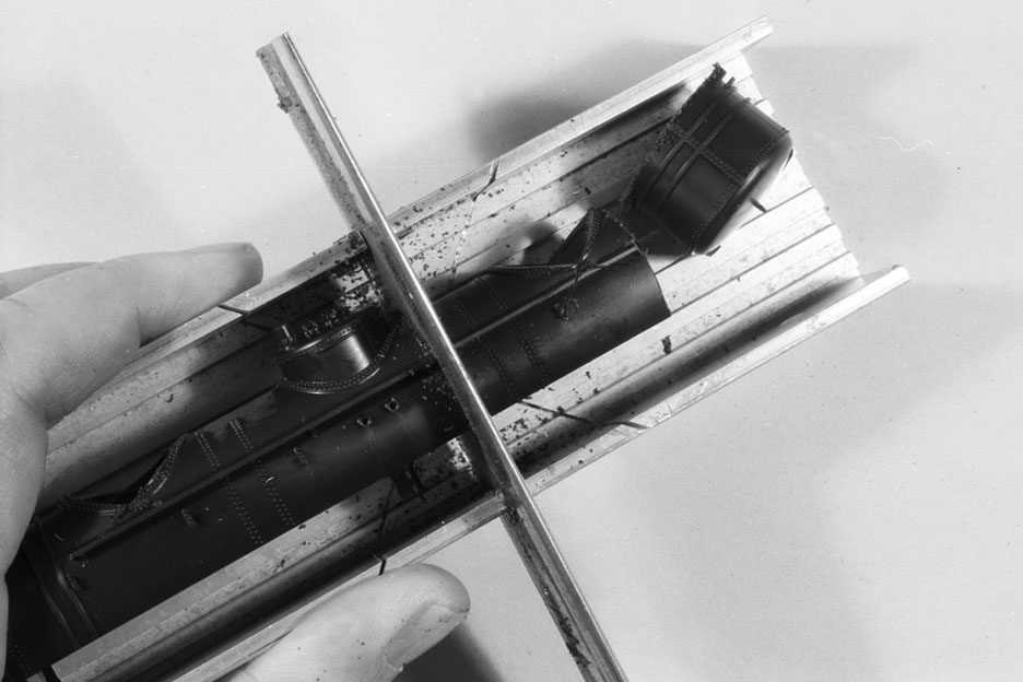
Note at right that the end has already been cut off, just inside the tank hold-down bands. I’m cutting here at a point close to, but to one side of, the center dome. I then would make the same cuts on the other end of the tank body. Then when the tank body is cut into five pieces, they are rearranged as shown here:

The whole purpose of this exercise is to relocate the craters (where domes were removed) away from the tank ends and nearer the center. The reason will be obvious in a moment. Meantime, I square up all the cuts with a file, and glue them all together, using lots of styrene cement and pressing very firmly so that any irregularities will be softened and squeezed out of the joints. Then rubber bands hold it together to get fully set (some modeling putty has already been applied):

Below is a photo showing a single-dome tank body at top (with dome height corrected), in the center the rearranged (and puttied) tank body I just described, and at bottom a triple dome tank with outer domes harvested but not cut up into five pieces. It can readily be seen that a tank with five circumferential tank sheets of equal width will cover the rearranged tank holes of the middle tank, but a joint would fall into the center of the outer holes of an unmodified tank. You will see in my second method how this bottom tank can be worked with.

One of my two methods is to use clear styrene, of 0.005-inch thickness, to make those circumferential sheets which sit atop the center and outer sheets, and use a scriber to indent rivets (using fine-spacing graph paper underneath to guide straight and uniform rivet rows--that’s why clear styrene was chosen). Here’s a model made that way, of the O-50-10 class:

Lettering is from the decal artwork now offered by Jerry Glow (http://home.comcast.net/~jerryglow/decals.html). This method certainly works, but the rivets are both a bit too large, and a bit too rounded, not as crisp as prototype rivets would be. The model, in other words, is fine if you don’t examine it too closely. It wouldn’t be confused with an Athearn tank car, but isn’t very refined either.
My second method was an effort to improve the rivets. Having seen the superb products of Archer Fine Transfers (see their products at: http://www.archertransfers.com/SurfaceDetailsMain.html), this seemed like a really obvious chance to use them. [You may note that Archer’s product line is heavily slanted toward 1:35 armor modeling, but railroad products are there too.] These rivets do work, though putting black rivets over a black tank body cannot be recommended; in future I will do a gray primer or equivalent before adding rivets, or else use white instead of clear styrene. Here is how it looked on the first try. I thought I wouldn’t need to slice up and rearrange the body, but just put one big overlay, with one edge flush against the tank bands, and a second one on top of it, so you can see here where the former dome’s hole is located:


Now in my opinion, these look good, though the rivets are a little too widely spaced. But they were rather tedious to do, because I had to get the staggered arrangement with careful application of two separate rivet rows. I promptly contacted Archer and offered to provide information on tank car double rivet rows. They were very receptive, and as soon as I sent them the data, they produced a new product (in both HO and N scales):
They were even kind enough to credit me at the bottom for supplying the data. So if you want to do tank cars with circumferential rivet rows, now it’s practical. Whether you cut up and rearrange tank bodies to prepare your tank car depends, I guess, on just how many Scottish genes are in your heritage.
Tony Thompson
Thursday, June 9, 2011
Tank car modeling
Back in December 2010, I summarized the tank car projects I was finishing to take to the January 2011 Cocoa Beach meeting, called “Prototype Rails” (you can view it at: http://modelingthesp.blogspot.com/2010/12/tank-car-projects-for-cocoa-beach.html). In that post, I just summarized the approach I was taking to the different tank cars.
After that early January meeting had ended, I posted photos of the two cars involved in the “tank swap,” based on an Intermountain 8000-gallon tank car kit and an Athearn “chemical” tank car kit. These were shown at: http://modelingthesp.blogspot.com/2011/01/tank-car-projects-for-cocoa-beach-2.html. As I said at the time, it was my plan to write up this tank swap between the two kits for magazine publication. I did so, and it’s now been published. It is included in the July 2011 issue of Railroad Model Craftsman.
I wanted to post this because I have had a couple of off-blog emails asking for more details on the cars shown in that post from January. In deference to RMC, I told those folks to wait for the article to come out. I hope the article is clear enough about what I did, and would enable anyone else to duplicate the work, or better yet, get ideas from it which could lead in some other direction.
I make that last point because my model of the Warren insulated car was inspired by an article by Mark Feddersen, even though I did several things a little differently than Mark did. (His article has the following citation: Mark Feddersen, “ICC-104 Insulated Tank Car,” Mainline Modeler, October 1985, pp. 63-69.) Here’s a repeat of my photo of that car (duplicating what I showed previously as well as what is in the magazine version).

Modeling details and specifics on the car configuration are, as I said, in the RMC article. More later.
Tony Thompson
Modeling diesel locomotive chronology-2: roadswitchers
Back in March of this year, I posted some thoughts on modeling the chronology of diesel locomotives on the Coast Line (available at: http://modelingthesp.blogspot.com/2011/03/modeling-diesel-locomotive-chronology.html). In that post, I summarized the history by saying that the 1953 diesel fleet operating on the Coast was dominated by EMD F7 road locomotives and by Baldwin roadswitchers, but that both EMD SD7 and Alco RSD-5 locomotives did have tryouts, however brief, on the Coast.
My model locomotive fleet is dominated by steam, as was the Coast Line in 1953, the last year when that was true. Moreover, I have several A-B and A-B-B sets of F7 models. But I do also have models of all three relevant types of roadswitchers. Here’s a view of them in my staging yard (any of them could be called for the Surf turn):

The models are a Stewart/Kato model of an Alco RSD-5, number 5301, which I decaled in its entirety, and also added one of Rob Sarberenyi’s “fat stacks” (nearest the camera); a Hallmark brass model of a Baldwin AS-616 with dynamic brakes, which I painted, decaled, and numbered 5249; and a Proto2000 SD7, numbered 5324 (and detailed and finished by Seth Neumann). Back two tracks is an A-B set of F3 Phase IV units, redetailed from Athearn shells. And by the way, at right is Consolidation 2752, waiting to handle the Guadalupe local.
The turns and locals referred were discussed previously in a couple of posts, notably the portions of my interview with Mac Gaddis, available at: http://modelingthesp.blogspot.com/2011/01/modeling-freight-traffic-coast-line_19.html. Perhaps to avoid confusion I should admit that the photo above does not represent the normal state of the staging yard, with three potential Surf turns all lined up on adjacent tracks, but is just arranged so a group photo could be taken. The various freight cars, however, are very much as they would normally be.
Because these diesels all represent locomotives uncommon in road service, though more likely to be found in local and branchline service, I intend to use them the same way, even though steam will be the most common power.
Tony Thompson
Saturday, June 4, 2011
Modeling SP tank cars, Part 2: handrails
There is an important omission in my post about modeling SP tank cars, namely how handrails are modeled in light of the changes in the tank arrangements. (This was brought to my attention in a detailed email from a reader of the blog, to whom my thanks are due.) My original post can be viewed at: http://modelingthesp.blogspot.com/2011/05/modeling-sp-tank-cars.html.
There are several issues involved in the tank handrail. First, as I mentioned in the original post, one can either use the Athearn handrail supports which are cast on the tank (less visible on a black tank car) or substitute the fine brass ones from Precision Scale. This in turn suggests a second issue: what diameter should this handrail be? Prototype handrails were 1.25-inch (nominal) iron pipe, which, as any table of nominal pipe sizes will tell you, has an outside diameter of 1.66 inches. This corresponds almost exactly to 0.019 inches in HO scale, and brass wire of that diameter is available from Detail Associates. The Athearn handrail wire is thicker, close to 0.026 inches. If you replace the Athearn handrails with smaller brass wire, no problem, but some modelers do like to use the Athearn wire. I’ll touch on how to do that below.
The Precision Scale handrail stanchions, their part no. 32110, are probably intended for 0.015-inch wire but can be carefully drilled out to 0.020 inches to accommodate 0.019-inch handrails, which is what I’ve done on several tank cars. Use of these stanchions also permits reducing the number of handrail stanchions on the tank to that of the prototype (see for example the builder photo of SP Class O-50-13 in my previous post). If you go this route, the Athearn handrails can be used as a template to bend a new 0.019-inch brass wire handrail to go all the way around the tank, in other words a one-piece handrail instead of Athearn’s two-piece design.
For those who want to use the Athearn handrail, the problem comes with the fact that the original tank body is set up for a ladder on each side, but the SP cars only have a ladder on one side, so the Athearn handrails obviously can’t just be attached as originally intended. The iron wire used by Athearn is evidently cold-formed and is very brittle, much too brittle to straighten at room temperature. But if you have a gas stove, you can heat the ladder-end bend in the Athearn wire until it’s at orange heat, then immediately use pliers to straighten it (if you are even a little late, it cools enough to return to brittleness). It’s worth practicing on some scrap wire, if you’re going to try this. As you can tell, I have tried it and have made it work, but you have to straighten it when it’s really hot.
So if you do this, instead of the two U-shaped wires provided by Athearn with bends at each end to drop into the ladder-top holes on each side, you have instead two U-shaped wires with only one bend (if you want to preserve the Athearn ladder attachment) or no bends at the ends. Now you have to cut them to fit, and join them. The joining problem, of course, exists also if you bend a new handrail from brass wire.
I use a solution to this problem which is apparently an old one, but I learned it from Ted Culotta in his “Essential Freight Cars” series in Railroad Model Craftsman. It involves a piece of hypodermic tubing which will just slip over the ends of the wire handrail. The key is that this tubing has very thin walls. Here’s a clear photo of how it looks when it’s installed (obviously unpainted), from one of Ted’s articles.

The small length of stainless steel tubing is just to the right of the Precision Scale handrail stanchion. For the 0.019-inch brass wire, you can use 0.020-inch inside diameter hypodermic tubing (available from Small Parts at www.smallparts.com – the smallest quantity is 12-inch lengths, and if that’s not more than a lifetime supply for this purpose, you are indeed a serious tank car modeler). If you‘re using the thicker Athearn wire, you want tubing to fit, namely the 0.029-inch inside diameter tubing. A small drop of CA glue will hold this tubing in place.
This approach to the problem of closing one or more joints in a tank car handrail is elegant and all but invisible when completed; and to the extent that it is visible, it looks something like the prototype pipe union actually used for this purpose.
Tony Thompson
Thursday, June 2, 2011
Waybills, Part 8
I realized in discussing the way I manage my waybill operations that I haven’t made clear the handling of empty cars. As mentioned earlier, the prototype used a form which was as tall as a regular waybill but only half as wide (to accommodate the common practice of folding waybills in half the long way), and these were used to move empty cars. This form was usually called an Empty Car Bill or something along those lines.
Here’s an example of one such document, from the Erie:
 As with waybills and other prototype forms, there is more information allowed for in the form than we generally need in model forms. So as with other waybill-related forms, I’ve made a simplified model form. There is more information about the use of these in a model waybill system in my two published articles:
Before showing my current model forms, it should be emphasized that these prototype forms differed from waybills in that they only were valid on the road which issued them. Upon reaching a junction with another railroad, the receiving railroad might choose to confiscate the car for use on that railroad, or could send it empty to its owner if there was a direct connection, or send it further along the reverse service route. But whatever the routing, it would have to be identified on a new Empty Car Bill issued by the road on which the car was now located.
On a particular railroad, it might be known that cars of a certain type, let’s say flat cars, were needed for loading at another point on the same railroad, in other words, that the empty car might be confiscated. In that case, the Empty Car Bill would not direct the car to the junction from which it was received loaded, but would be directed to the loading point which needed flat cars.
As can be noted on the Erie prototype form shown above, the same form can be used to route cars homeward (Home Route Card) or to move empties in any other way needed (the Empty Car Waybill). I’ve retained that distinction on my model Empty Car Bills. And although I originally intended to identify car type (box, flat, etc.) on the Empty Car Bill, it really isn’t needed with my design of car sleeves, because the car type is on the sleeve. I’ll illustrate.
Here is an Empty Car Bill, in a car sleeve, with the sleeve showing the AAR class identification. It is clearly a box car made empty at Shumala and now to be moved to the next major terminal northward (SP westward), Oakland.

This kind of Bill permits movement in either the logical direction homeward, or in a direction specified by an “Equipment Instructions” document (the latter was explained, and an example given, in a previous post on freight traffic, at: http://modelingthesp.blogspot.com/2011/01/modeling-freight-traffic-coast-line_30.html).
Inbound empty cars are ordinarily directed to the destination agent, not to a specific industry. When the switch crew arrives at that town, the agent will tell them where the car goes, or if the agent is not on duty when they arrive, there will be a message waiting for them in the “bill box” on the outside of the depot or freight station. However, a shipper request does result in a particular car type being needed, so my inbound Empty Car Bills “For Loading” have that AAR designation in the upper part of the form, and of course the selected car has to match that designation:

A stock of the ones without AAR designation are kept at each town to facilitate movement of empty cars after unloading. Bills for inbound empties for loading, however, are managed as part of the same waybill system as inbound loads. So far this approach, using two types of Empty Car Bills, has been working well for handling empty cars on my layout.
Tony Thompson
Here’s an example of one such document, from the Erie:

“Prototypical Waybills for Car Card Operation,” Railroad Model Craftsman, December 2009, pp. 71–77.
“Contents of a Waybill,” The Dispatcher’s Office (publication of Operations SIG), April 2010, pp. 17–24. (A corrected version of this article was presented in a prior post, at: http://modelingthesp.blogspot.com/2011/01/waybills-2.html.)
Before showing my current model forms, it should be emphasized that these prototype forms differed from waybills in that they only were valid on the road which issued them. Upon reaching a junction with another railroad, the receiving railroad might choose to confiscate the car for use on that railroad, or could send it empty to its owner if there was a direct connection, or send it further along the reverse service route. But whatever the routing, it would have to be identified on a new Empty Car Bill issued by the road on which the car was now located.
On a particular railroad, it might be known that cars of a certain type, let’s say flat cars, were needed for loading at another point on the same railroad, in other words, that the empty car might be confiscated. In that case, the Empty Car Bill would not direct the car to the junction from which it was received loaded, but would be directed to the loading point which needed flat cars.
As can be noted on the Erie prototype form shown above, the same form can be used to route cars homeward (Home Route Card) or to move empties in any other way needed (the Empty Car Waybill). I’ve retained that distinction on my model Empty Car Bills. And although I originally intended to identify car type (box, flat, etc.) on the Empty Car Bill, it really isn’t needed with my design of car sleeves, because the car type is on the sleeve. I’ll illustrate.
Here is an Empty Car Bill, in a car sleeve, with the sleeve showing the AAR class identification. It is clearly a box car made empty at Shumala and now to be moved to the next major terminal northward (SP westward), Oakland.

This kind of Bill permits movement in either the logical direction homeward, or in a direction specified by an “Equipment Instructions” document (the latter was explained, and an example given, in a previous post on freight traffic, at: http://modelingthesp.blogspot.com/2011/01/modeling-freight-traffic-coast-line_30.html).
Inbound empty cars are ordinarily directed to the destination agent, not to a specific industry. When the switch crew arrives at that town, the agent will tell them where the car goes, or if the agent is not on duty when they arrive, there will be a message waiting for them in the “bill box” on the outside of the depot or freight station. However, a shipper request does result in a particular car type being needed, so my inbound Empty Car Bills “For Loading” have that AAR designation in the upper part of the form, and of course the selected car has to match that designation:

A stock of the ones without AAR designation are kept at each town to facilitate movement of empty cars after unloading. Bills for inbound empties for loading, however, are managed as part of the same waybill system as inbound loads. So far this approach, using two types of Empty Car Bills, has been working well for handling empty cars on my layout.
Tony Thompson
Subscribe to:
Posts (Atom)