Friday, January 29, 2016

Shumala engine terminal, an update

It has been some time since I have commented on progress with the engine terminal at Shumala. It was described in 2011 as it then was, in a post which also described plans for it (see it at: http://modelingthesp.blogspot.com/2011/04/modeling-engine-terminal.html ). Among those plans was to build the Banta Modelworks kit (which represents SP’s roundhouse at Port Costa, California), and I have now completed that structure. I’m very pleased with how it turned out. For more on my build of the kit, you can work backward from the concluding post in a series (it can be found at: http://modelingthesp.blogspot.com/2014/02/a-roundhouse-for-shumala-part-5.html ). You can see it in the background of the photo below.
     I have also added a long-planned caboose service building alongside the caboose track, using the body from a Westerfield kit. It too is at the engine terminal (a project description is at: http://modelingthesp.blogspot.com/2014/03/a-caboose-service-building.html ). Another principal feature of the terminal is the 88-foot turntable, built from a Diamond Scale kit, which has worked well in operating this terminal.
     But recently I have received two different emails asking specific questions about the Shumala engine terminal details, so thought I would expand a little on the foregoing posts. I mentioned in the first of the prior posts cited above, that both a water storage tank, and a fuel tank, needed to be in place as sources for the fuel and water columns at the terminal. Those can be seen at the left of the photo below, with the 65,000-gallon water tank (Overland Models brass) alongside the roundhouse, The oil tank further right is scratchbuilt.


On the turntable is 2-8-0 SP 2829 (Sunset brass, Max Gray tender), and on the garden track next to the roundhouse is 4-6-0 SP 2344 (Precision Scale). In the foreground is Alco S-2 SP 1389 (Atlas), just forward of the fuel and water columns.
     Note also in this photo the red Associated Oil Company delivery truck near photo center, which has just fueled the diesel — the SP has not build diesel fueling facilities here yet. In the background at right is part of the Associated Oil dealership here, described in an article in the March 2014 Model Railroad Hobbyist (downloadable for free any time from their site, www.mrhmag.com ) and also mentioned in a prior post (that one is at: http://modelingthesp.blogspot.com/2014/03/associated-oil-co-modeling-oil-dealer.html ).
     At lower left is a single caboose on the caboose track, where there are often two; this suggests that the Santa Rosalia local is still out on the road, using that second caboose. And at the upper left, just in front of the 65,000-gallon water tank, can be seen an SP tank car delivering Bunker C locomotive fuel for the steam power.
     This terminal still lacks a sand house, and I have a project started to build one from scratch. More about that when it happens.
Tony Thompson

Tuesday, January 26, 2016

Running boards, Part 2

In the previous post in this series (see: http://modelingthesp.blogspot.com/2016/01/running-boards.html ), I discussed the arrangement of prototype wood running boards, and indicated some of the issues related to how models should represent prototype appearance. In the present post, I describe modeling approaches.
     To start, it is easy to add a scribed cross-groove to any undivided running boards on a model. In the photo below, a scriber is being used to do so on a Red Caboose ice-service refrigerator car.


     Next, variations in appearance can be added. As I mentioned in that previous post, there are several possible patterns of appearance on a prototype running board. First, individual planks may vary in how weathered or faded they look, though all were originally applied and painted at the same time. Second, replacement boards may be freshly painted (or even unpainted), then weathered or faded to varying degrees. And third, a plank may even be missing. In this post, I experiment with the first case.
     If working to improve an existing model, the easiest way to vary the color of individual planks in running boards is to use color pencils. My experience with different brands of these, available at any art supply store, is that Prismacolor pencils are definitely superior for modeling. There are a great range of brownish-reddish colors, and several similar gray colors.
     For grays, I usually use French Grey 30%, French Grey 50%, and Warm Grey 20% (I don’t know what the percentages indicate, but there are lots of them); for the reddish-browns, I use Sienna Brown, Chestnut, Dark Umber, Light Umber, Burnt Ochre, and Chocolate. These can be very lightly stroked over the painted and weathered running board surface of a previously completed model. For a model not yet weathered, more color could be applied, as weathering will then soften and blend it somewhat.
     Shown below is the same Broadway Limited New York Central box car depicted in the prior post, receiving a little grayed color with Prismacolor 30% French Grey.


As another example, the photo below shows a Red Caboose SP stock car, getting a little variation in its running board paint color using Prismacolor Burnt Ochre. Some gray has already been added, and if the gray seems too vivid, it can be overcoated and softened with the reddish color.


     Using these colors, the running board of the PFE ice service reefer shown in the first photo of this post was given a variety of varied looks. The scribed lines, which sometimes look light in color even if the styrene of the material is boxcar red, can be darkened with the sharp tip of one of the darker Prismacolor pencils. (Note that ice hatch are removed and the locations of the openings are blanked off, as PFE often did with ice service cars; ice bunkers inside the car were also removed.) You can click on the image to enlarge it if you wish.


      I have been working my way through my freight car fleet, finding neglected running boards which need some variation in color. I have added this kind of weathering / coloring haphazardly for years, but obviously never consistently, because I am certainly finding a number of cars with running boards which need dividing into planks, or need color variation, or both. I will also explore more vivid variations in running board appearance in a future post.
Tony Thompson

Saturday, January 23, 2016

Waybills, Part 48: Multi-compartment tank cars

I recently received a question about tank cars by email, and it’s a very good question. I was asked, “How was a multi-compartment tank car waybilled?” As it happens, I was shown such a prototype waybill some years ago, and though I don’t know if that example was universal or even typical, I do at least know that one example.
     (For a thorough and complete discussion of prototype tank cars with multiple compartments, see Richard Hendrickson’s article in the February 2015 issue of Model Railroad Hobbyist, available free to read or download at: www.mrhmag.com .)
     In the example I saw, each compartment’s cargo was separately identified, and the gallonage shown. Multi-compartment cars normally had the gallons capacity of each compartment stenciled on the dome, along with an identifying letter (A, B, C, etc.), and usually the B compartment was at the B end of two- or three-compartment cars. That’s the scheme you see in this photo of a three-compartment GATX car (obviously converted from a single-compartment car, as testified by the smaller expansion domes at each end). The photo is from the Richard Hendrickson collection; you can click on the image to enlarge it.


The nearest end compartment is “A” and it is at the A end; the center compartment is “C.” Note that there is no gallonage stenciled on the car end, as would be normal for a tank car, because, as mentioned, each compartment’s capacity is stenciled on its expansion dome.
     Another scheme for identifying compartments is shown in the photo below, of a six-compartment GATX wine car (from my own collection). At the B end, compartments are B-1, B-2 and B-3; at the A end, they are A-1, A-2 and A-3. The endmost compartment is number 1 in each case.


     The particular model I am working toward at the moment is a Southern Car & Foundry two-compartment car, kit 2001. This represents a Standard Tank Car design, with its distinctive bolsters, and is similar to a Richfield Oil tank car of which I have a fuzzy photo. Here is the model, ROX 792, photographed being switched on my layout at Santa Rosalia; its dome walkway is on the other side.


     The waybill format I was shown, as I mentioned at the top of this post, is like the one shown below, and it is for the Richfield model shown above. It is for a load from the Richfield Oil Company refinery in Watson, California (now Carson), which was located on the Pacific Electric, to a bulk oil dealer in the town of Santa Rosalia on my layout.


     When this car is made empty, it returns to the refinery on a conventional freight waybill for privately owned tank cars, like the one shown below. These normally include the language shown, “record rights, reverse route.” The notation ”L / C” means “last contained.” Note also the common practice of the return “shipper” being the local agent, not the original recipient.


     I have a number of multi-compartment tank cars in my fleet, and will develop waybills for them along the lines described in this post.
Tony Thompson

Wednesday, January 20, 2016

Running boards

In this post I will discuss wood running boards only. In the late 1930s, as the first steel-grid running boards appeared on the market, some car owners began to change over to these stronger, longer lasting, and safer appliances. In the summer of 1944, however, that change ceased to be optional, as at that time newly constructed cars were mandated to have running boards “other than wood.” All new cars (except tank cars, exempted until 1948) thereafter had steel running boards of one kind or another.
     But wood running boards were not required to be replaced on older cars, unless a running board repair was required. Accordingly, well into the 1950s many house cars could be seen with their old wood running boards. The topic of this post is, what did they look like? and how should our models look?
     Many models, for years, have had running boards represented as though the boards extended for the full length of the car. Forty-foot planks were neither common nor cheap, even in the heyday of Western logging, so this is an improbable arrangement, but models have often been produced this way. Here is an example (I will not identify the maker):


This is an example of the three running board planks being unbroken from end to end of the car. It seems to me that the least one should do is recognize that real running boards were made up of multiple planks. Some newer models are in fact manufactured this way. Below is one end of a Broadway Limited New York Central 40-foot steel box car. Each board comprises three separate planks. (You can click to enlarge.)


     At each end, plank ends are located at the third and fourth roof ribs. Measuring the three boards, all three have an approximately 11-foot plank at one end, a 14-foot plank at the other, and a 17-foot plank in the center, but the 11- and 14-foot plank locations are reversed on the center board, relative to the two outer boards, to stagger the joints. (These are nominal dimensions, depending on the exact spacing of running board supports on the roof; roughly 3 feet is common.) Car drawings in different volumes of the Car Builders Cyclopedia do not always show running board divisions, but when they do, they agree with the arrangement just described on this particular model.
     Any model with running boards shown as full-length planks can be given scribed lines to indicate board ends, or even a simple pencil line will suggest the presence of a joint (located, of course, exactly at running board support positions on steel roofs). That would be the first step. Whether one chooses to try and model the bolt heads that attach the planks to the running board supports, is a personal choice, but often these heads were countersunk, so that crewmen atop a car would have a smoother walkway.
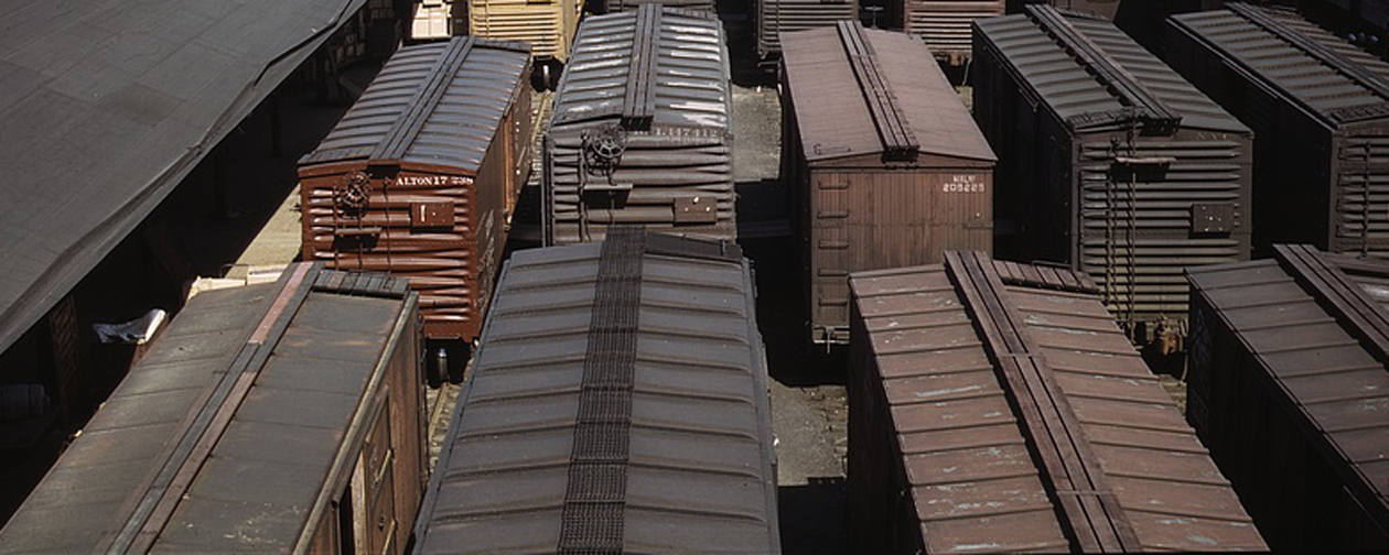
     But there is more to the story. The wood planks were fully exposed to weather of all sorts, and inevitably the paint-holding ability would vary from plank to plank. That in turn would result in some planks showing more weathered or faded paint than others. Here is a portion of a prototype photo from April of 1943, taken by Jack Delano at the Galewood yard of the Milwaukee Road in Chicago, Illinois (Library of Congress photo LC-USW361-619).


Note that most of the wood running boards shown have variations in appearance, especially at the left of the nearest row of cars, and the third and fourth from the left in the second row. In fact, that first car at bottom left looks as though the boards are replacements, with cleaner paint than the remainder of the running board. Even the Alton box car at upper left, looking freshly painted, shows some variation in the darkness of color on its running board planks. But do note that almost all variations are subtle, not glaringly obvious.
     (Note also some paint failure on roofs, primarily the car second from left in the upper row, and to a lesser extent on the car third from left in the bottom row. But most cars here, as in most photos from this era, show little or no failure of this kind.)
     From this photo, we can suggest several patterns. First, individual planks may vary in how weathered or faded they look, though all were originally applied and painted at the same time. Second, replacement boards may be freshly painted (or even unpainted), then weathered or faded to varying degrees. And third, a plank may even be missing, though such a car would be bad-ordered upon discovery of the defect, so such cars would be rare.
     How would we go about modeling these variations? There are a number of options, and that’s the topic of the next post in this series.
Tony Thompson

Sunday, January 17, 2016

Cocoa Beach 2016

The sixteenth annual Prototype Rails meeting at Cocoa Beach, Florida, was held this year during January 7 to 9. I attended, as I have done for all but the first of these meetings, and as usual it was an excellent gathering, with a strong clinic schedule, an outstanding model display, a big vendor room, and lots of corridor encounters and conversations. The Cocoa Beach Hilton continues to do a fine job of hosting, and 268 people registered this year.
     Mike Brock continues to ably organize and direct these meetings, with the assistance of several local modelers, notably Marty Megregian, who manages the ballroom displays; these include portable layouts, models, manufacturers’ tables, and vendors. Here’s a view of that ballroom, with Mike at far left and Marty next to him. And directly to the right of them are Steve Funaro (kneeling down) and Sharon Camerlengo, long-time regular vendors at this meeting, offering a very large selection of their fine kits. (You can click on the image to enlarge it.)


     Jeff Aley, clinic chair, continues to do a fine job of putting together a clinic schedule with excellent breadth and strength. Among the familiar notables speaking to large crowds was Tony Koester, whom you see here just about to begin his talk. His title slide is on the screen.


     A highlight for me is always the model displays. Some attendees are able to bring substantial numbers of models (usually those who live fairly close). One of them every year is Bruce Smith, who this year displayed his models as complete Pennsylvania Railroad trains (the reefer train is in two parts).


I liked several of the passenger cars displayed this year, especially the 12-2-3 Pullman Elm Trail (Plan 4158) by Jim Murrie. I have left the car description in the photo so you can see what he did.


Also very nicely done was this pile driver by Mark Hooper. It’s scratchbuilt except for the SS Limited two-drum hoist and hammer, and a number of commercial small parts. (The caboose behind it was part of another display,)


     Among the minority of modern models was a group by Bob DeStefano, and he helpfully included prototype photos to demonstrate his goal with both the car body and paint job for each model. I often needle those modern modelers who don’t include graffiti on their freight cars, but obviously Bob is not in that group. These were all very well done.


     Last, I very much liked this model by James “Chip” Syme, whose displayed models were all Conrail cars. Gondolas take a beating in service, and often show missing floor boards and other damage, and this Penn Central model really shows that.


     I always enjoy the entire Cocoa Beach meeeting, and this year was no exception. The many fine modelers who attend, and the very nice venue, really complete an excellent experience. If you have never been to this meeting, held around the second weekend in January, you might think about attending next year. I know you would find it worthwhile.
Tony Thompson

Thursday, January 14, 2016

Recent freight car projects

I am occasionally asked what car projects I’ve been doing. When a car project has some aspect that may be out of the ordinary in some way, I probably would write about it on this blog. But many cars that get completed are not particularly noteworthy, thus not ordinarily the subjects of posts. Still, I understand that readers may like to see photos of model freight cars. So in this post I show a few of mine that are recently completed.
     I will start with a model kitbashed from an Athearn 50-foot gondola, with side sills cut down to a straight configuration, and with the addition of drop ends and a wood floor. This model, PMcK&Y 91783, is not an exact match to the Pittsburgh, McKeesport & Youghiogheny prototype, but is a suitable stand-in. The model was built some years ago, following a old Richard Hendrickson article  (Prototype Modeler, November-December issue, 1982, pages 12-16), but only recently completed. The load is made from soda straws (see the method at: http://modelingthesp.blogspot.com/2012/01/open-car-loads-pipe-in-gondolas.html ). You can click to enlarge.


     A resin kit I inherited from Richard Hendrickson was a C&O double-door box car with end doors, a Yankee Clipper kit (no. 1930.95). I had Dennis Williams build it, and as usual I did all the finishing. In the photo below, C&O 9742 is shown being picked up by the Santa Rosalia local from the house track at Ballard on my layout.


     Here is another example, SAL 19107, railroad class B7, built by Dennis Williams from Sunshine kit 55.9, and lettered and weathered by me. I chose the prewar paint scheme with the plain railroad emblem (no red heart) and the Silver Meteor slogan. This is a distinctive Seaboard box car, one of the prewar classes with the “wagontop” roof (as Pennsy people called it), and with distinctive ribbed ends. It was photographed in a train just leaving Ballard on my layout.


     I don’t own all that many brass freight cars, and most of them are tank cars at that, but here is one example of a brass house car, recently finished by me. It’s an Overland model, of a 40-foot double-door box car, single-sheathed and with wood doors, lettered for the Wabash prototype of this brass model, WAB 45218. It’s shown near the depot at Shumala.


     I should also include a recent ready-to-run car, so among the ones I’ve added lately is this InterMountain tank car, in the scheme of the Gibson Wine Company of Elk Grove, California. (Decals for this company in HO scale are available from Protocraft (visit http://www.protocraft.com/Majors.cfm?ID=1 ). The model is somewhat dirtied along the top, otherwise not very weathered. And because wine is a non-regulated commodity, it naturally has no placard. Here you see GATX 66714 being switched at Shumala.


One naturally and correctly associates wine tank cars leased by winemakers as being used to ship product from that winery or wine company. But several pieces of evidence point to additional use for such cars, moving purchased wine from other wine companies to the car lessee’s property. (For more on wine as an industrial commodity, see my blog post at: http://modelingthesp.blogspot.com/2012/02/wine-as-industrial-commodity.html .) I envision this Gibson-leased car as doing just that, and being loaded with blending wine at one of the wine producers on my layout.
      These cars are representative of my recent fleet additions, and I hope these photos will be of some interest. With luck, they might even provide a few ideas.
Tony Thompson

Monday, January 11, 2016

Waybills, Part 47: The stop-off form

In a prior post, Part 45 of this series on waybills (you can read that post at: http://modelingthesp.blogspot.com/2015/12/waybills-part-45-preferred-movement.html ), I described a special waybill form used for “preferred movement” cargoes, to make that particular car a priority handling car. But there are other standard forms which are also of interest, and in the present post I discuss another one used to make sure a cargo is properly treated.
     Among the many specialized forms shown in that essential book, Railway Accounting Rules (AAR), is one to help ensure that cars that were to stop off en route, to partially unload or complete loading, were not missed. It was naturally called a “stop off” document, and was in fact an envelope, with the normal waybill inside. It can be found on page 184 of the book just cited (I use the 1950 edition).
     The regular waybill would of course have the directions for the car to stop off at one or more locations, but this was evidently easily missed. And incidentally, I notice the same with people operating of model layouts — they tend not to read the waybill very carefully, and thus miss the stop-off provision. The document I am talking about, AAR Form AD-142, was recommended, not mandatory, and was specifically intended to help with situations where stop-off directions were being missed.
     Though the prototype form was a manila envelope, I intend to use it as a supplementary waybill atop the regular waybill, and indeed, the form as designed has information on the exterior which can serve as a waybill. When the stop is fulfilled, however, the car then has a further destination, so the conventional waybill will also be provided crews for that second move.
     Shown below is the form, as reproduced in the book. The very large center legend certainly ought to do the job of alerting crews.


The directions at the bottom, having to do with placement of yard and junction stamps, are not needed for most model layouts and I will omit them. The directions at bottom also specify that this is to be a manila envelope, so manila-colored paper or card stock will be the material I use.
     I simply worked with the scan shown above to alter shape and size to fit my waybill format, which is about 2.5 x 3.5 inches (baseball card collection size). The first one I made up was for Southern Pacific. The modified form then looked like this:

I have kept the center part of the form, likely intended for handwritten information, but intend to make up these documents as though typed. As mentioned, the material is supposed to be manila, so here is an example of my model implementation with manila cardstock, together with the accompanying waybill. You can click to enlarge.


The Stop Off form will be placed atop the regular waybill, as I will use it in a plastic sleeve, and after making the stop identified, the stop-off form is removed, exposing the regular bill for continued movement, in this case to Los Angeles.
     The same form can be readily adopted for the “Micro-Mark” size of waybills, as used for example on Otis McGee’s layout. One could either use the taller form like the prototype (see upper image in this post), or simply leave blank space at the bottom. I chose the latter, and here is an example of this particular form:


     These Stop Off forms add variety (and hopefully interest) to waybill procedures on an operating layout, and should be the source of added attraction for switch crews which encounter them.
Tony Thompson

Friday, January 8, 2016

Southern Pacific diesel chronology

A few years ago I posted some comments about modeling SP’s diesel chronology, so I could accurately depict my modeling year of 1953 (see: http://modelingthesp.blogspot.com/2011/03/modeling-diesel-locomotive-chronology.html ). In that post, I alluded to an article I published some years past in the Southern Pacific Historical & Technical Society magazine, Trainline, in issue 29 (the magazine was not dated in those days, but I believe that issue came out in 1992), pages 18–23. The printed back issue is still available for sale (to buy it, visit: http://sphts.org/store/trainline-back-issues.html ), but I decided the article needed more visibility.
     I have scanned all six pages, and made a PDF document, then put it onto Google Drive. If you would like to see it (or download, if you wish), here is the link:

https://drive.google.com/file/d/0Bz_ctrHrDz4wallIS2ZaTFpxYlE/view?usp=sharing

     This article gives delivery dates, to the month, of all diesels acquired by Southern Pacific’s Pacific Lines up to 1956, and also contains some representative photos. A bibliography documents the sources of all information. I hope this is helpful to modelers of the transition era on the SP.
Tony Thompson

Tuesday, January 5, 2016

Two-sided freight cars

Reading the title of this post, you may be thinking, “Well, of course they have two sides . . .” but that’s not what I mean. I refer instead to freight cars with different lettering on each side. This is something I have not done recently, but Richard Hendrickson was fond of it for certain kinds of cars, and I thought it might be interesting to show a few examples.
     (For anyone not familiar with Richard, his career, and a few of his accomplishments, you may wish to read my appreciation of him, which is at: http://modelingthesp.blogspot.com/2014/07/in-memoriam-richard-hendrickson.html . I have also shown some of his fine models of freight cars in a couple of previous posts, such as: http://modelingthesp.blogspot.com/2015/03/richard-hendricksons-multi-car-loads.html , and also a depiction of the variety of lumber loads he built for his cars; you can see that post at: http://modelingthesp.blogspot.com/2015/06/richard-hendricksons-lumber-loads.html .)
     I will begin with a USRA gondola model, which was built from the old Walthers kit which had white-metal castings. Richard knew of several roads which still operated these gondolas with original wood sheathing as late as his modeling year of 1947, so built one model with two sides. Here is one of the sides, L&N 74348, with a load of metal scrap.


Note the end, which although photographed in shadow, is in fact seriously dirty from weathering. This might be a choice to show a dirty end, but has the convenience that now one cannot read road initials on the end which could conflict with the side lettering. Here is the other side, SL-SF 85327:


You will note that the weathering pattern and chalk marks are a little different on each side.
      Richard had been the source of prototype information on the Mather Patent box car models first produced by Proto 2000 (now Walthers), and received a whole box of the cars when they were produced. He wanted to depict two of the smaller roads which owned (or leased) them. He chose the Illinois Northern and the Port Huron & Detroit (both schemes were offered on the Proto 2000 kits). This side is IN 2059.


This is the other side, PH&D 1168. Here again, ends are pretty dirty.


      Another good prospect for this treatment is flat cars, partly because they have no end lettering. Years ago, Richard cut down a Roundhouse short flat car to make a gun flat. These are familiar as the Pennsylvania F22 flat cars, shown here as PRR 435376, shown at Shumala on my layout with a Westinghouse transformer load.


The Milwaukee Road had some very similar cars, so that was the basis for the lettering on the other side, MILW 67126.


      On layouts like mine,where there is no reversing loop, and accordingly one always sees the same side of any rolling stock (unless it is physically rotated to show the other side), cars like this are very practical. But of course in staging operating sessions, the correct waybills have to be selected for whichever side is visible in that session.
     I like the ability to portray more railroads with fewer models, and may construct a few cars like this myself. One additional possibility, for loads which need to be glued onto the car, is to have different road numbers on each side of the loaded car, and the same two numbers on both sides of an empty car, permitting the same two waybill pairs (loaded and Empty Car Slip) to serve both. And again, you do get two cars to operate, though both have the same load. This would be okay with a fairly generic load, such as lumber.
Tony Thompson

Saturday, January 2, 2016

Vachon tank car photos

My title refers to John F. Vachon, one of the Farm Security Administration photographers in the late 1930s. Among his FSA colleagues were such famous individuals as Dorothea Lange, Walker Evans, Carl Mydans and Arthur Rothstein, not to mention renowned railroad photographer Jack Delano. Vachon worked for the FSA from 1936 to 1941, then for the Office of War Information (OWI) during 1942 and 1943, when the FSA photographic group was moved to OWI. As these were government agencies, all his photographs from this time (and those of his colleagues in the same period) are in the public domain and readily available in digital form from the Library of Congress.
     One of Vachon’s assignments in the fall of 1942 was oil refineries, and he took many dozens of images, most at the Phillips refinery in Borger, Texas. (After leaving the OWI, he went to work as a photographer for Standard Oil, and created images for them until he joined Life magazine in 1947, and then Look magazine in 1949). There are several biographies of Vachon on the Internet for anyone wishing to know more about him.
     Most of Vachon’s refinery photos show refinery equipment, and many more show refinery workers. But a few show tank cars, and are of period interest. Some of these images only depict tank cars in the background or in the distance, but some are closer up and very informative. I show below a few of these, and each is identified with its Library of Congress (LC) negative number. These and many more images are readily viewed at the Library of Congress website with the use of these numbers. The full negatives were scanned, so the surrounding black frame is shown too, and the OWI negative numbers are shown at lower right of each frame (you may have seen images like this published with only the OWI identification).
     Here a string of Phillips tank cars is being loaded through the dome manway at Borger (LC-USW3-011623-D).


Another view of a loading platform shows the loading pipes, with rotating elbow joints, here loading an Oil States tank car (OSKX 443); the photo is LC-USW3-010112-D. The Oil States cars would soon become part of the Mid-Continent Petroleum fleet (COSX marks)


     Another photo from the series shows a workman starting to open a screw-top manway cover (LC-USW3-010108-D).


Note the shiny spillage on the side of the dome, more evident in the next shot of the manway open, and the workman dipping a sample of the cargo (LC-USW3-010110-D).


     Loading was quite different for pressure cars (ICC 105A types), containing such cargoes as propane or LPG. Both sampling and inlet hoses were connected to valves in the valve bonnet (not an expansion dome). Also connected was a relief hose, to conduct away any air or vapor already in the empty car, as the liquified gas filled the car  (LC-USW3-010331-D).


     When loaded, the cars naturally received appropriate placards, as you see here with an insulated pressure car (LC-USW3-011346-D).


    These kinds of images are very informative, as they can be found few other places. They literally relate of course only to 1942, but throughout the period from World War I until the late 1950s, these images are reasonably typical of tank car practice.
     My upcoming column in Model Railroad Hobbyist, which I understand will appear in the February 2016 issue, is about prototype tank cars, and will hopefully explain many of the details shown in the above Vachon photos, for those who may not already recognize them. But none of the photos shown in this post are in that MRH column.
Tony Thompson