Monday, January 29, 2024

PFE express refrigerators

I recently received an interesting comment from a long-time reader of this blog. The comment was, that I had mentioned PFE express refrigerator cars many times, but rarely had provided anything comprehensive about them. This is probably true about the blog, because of the PFE book (Thompson, Church and Jones, Pacific Fruit Express, 2nd edition, Signature Press, 2000), for which I wrote all the parts about PFE cars. Let me see what I can add; also compare Chapter 5 in the PFE book. 

The first point to recognize about PFE express reefers is that PFE owned a fleet of 300 very conventional wood-sheathed 50-foot cars, built by AC&F and General American during 1923–24, which were very similar to many other owners’ express cars in that period. One benefit for modelers in that fact is that a manufacturer can offer the “standard” General American express car in a variety of lettering schemes, and in fact Athearn (in the blue-box days) and Walthers have done just that.

As built, these cars had round roofs and flush ice hatches, that is, no hatch platforms, and side and end grab irons were arranged according to passenger-car practice. They were numbered 501–800. Below is a copy of a builder photo of these cars (AC&F photo, courtesy Gordon Mills). 

Note that the car is lettered for American Railway Express, the predecessor of the Railway Express Agency (REA), to whom the cars were leased for operation. Upon replacement of ARE with REA, the leases were terminated and cars returned to PFE. Subsequently, PFE, like most major owners of express reefers, voluntarily made them available for an REA pool.

As built, these cars were typified by a wide fascia board the full length of the car. Earl Hopkins, retired PFE General Mechanical and Engineering Officer, told me in an interview that these boards were 50-foot lengths of 10-inch wide clear redwood, as specified by PFE to the builder. 

Beginning in 1930, PFE partially rebuilt these cars, adding ice hatch platforms, ladders on car sides and ends in place of grab-iron rows, and generally rearranging safety appliances in accord with freight car practice. (Both the old Athearn and the Walthers models are a mixture of these features, having flush ice hatches, but side and end ladders.)

Below is an in-service photo of one of the cars, showing that wide fascia board, taken at Roseville, California  on May 7, 1956 (Chet McCoid photo, Bob’s Photo collection). Note that the car has a conventional power hand brake. These were installed when many of the express cars were overhauled during 1942–46, replacing Miner lever hand brakes. Note also that reporting mark and car number are to the right of the car door.

By 1953, the year I model, many cars were in poor condition, and PFE undertook to rebuild again 83 of the 155 cars then in service, about half of the fleet. Inside, the old wood superstructures were replaced with steel frames. The rebuilds are easy to recognize because the original wide fascia boards were replaced with a much narrower fir fascia board. Lettering was also revised, as seen in this photo at the Harborside Terminal, Jersey City, NJ, in 1958 (Jeff Winslow photo). Finally, fans were added (note fan symbol above nearer truck.)

Thus there are four different appearances shown by these express refrigerators, according to era. First, the as-built appearance, without ice hatch platforms or ladders. Second, the post-early thirties look with ice hatch platforms and ladders added. Third, the post-World War II look, with power hand brakes instead of lever hand brakes. Fourth, the final rebuilt look (only part of the fleet), with narrow fascia boards, from 1954 onwards.

For my own modeling, the post-World War II look, appearance 3, is appropriate for most if not all of my PFE express reefers. Probably the best commercial model of the post-WW II cars was the brass version by WP Car Company. I have a couple of these. Here is what they look like (weathered and in service on my layout):

Here is another model I have, weathered by Al Massi and traded to me by Otis McGee for a Richard Hendrickson PRR express reefer. I don’t specifically know the origin of the model, but it might be a Challenger brass import. In the early 1950s, the prototype cars had become rather dingy, and this model reflects that. 

In the 1950s, there were also some quite interesting PFE express cars in the form of 40-foot steel reefers. I will summarize their history and modeling in a future post.

Tony Thompson


Friday, January 26, 2024

Modeling an SP Class O-50-9 tank car, Part 4

This is a continuation of my project to model one of Southern Pacific’s tank cars with circumferential rivet rows joining the tank segments. The last class of such SP cars to be built was Class O-50-9, which I am modeling. I began with an Athearn tank car, dimensionally correct for the SP car, following the steps shown some time ago in a post about the corrections needed to the Athearn car (see that description at:  https://modelingthesp.blogspot.com/2011/05/modeling-sp-tank-cars.html ). 

With the new rivet rows placed using Archer Rivets, the body was approaching completion (more about that process was in my Part 3:  https://modelingthesp.blogspot.com/2020/09/modeling-sp-o-50-9-car-part-3.html ). In the repeated photo below, you can see the double safety valve (Owl Mountain Models) in an “elbow” mount on the right side of the raised dome and the new rivet rows (the dark ones; the light ones are remnants of the superfluous ones molded on the Athearn body, which were removed).

In that previous post, I had fabricated the first segment of the new handrail (visible above), but had not yet completed it. I have shown the process of making such a handrail in several places, most recently with a diesel-fuel tank car (here’s a repeat of that link: https://modelingthesp.blogspot.com/2023/06/sp-diesel-fuel-tank-car-conclusion.html ). As the car will be painted black, thus making the clunky Athearn handrail supports considerably less obvious, I decided to leave them in place. 

Joining two pieces of handrail, of course, requires some sort of connector. One way to do this, originally described by Ted Culotta in one of his modeling articles, is to use a short length of hypodermic tubing. For the 0.020-inch K&S brass wire being used on this model, you can use 0.020-inch inside diameter hypodermic tubing (available from Small Parts at www.smallparts.com – the smallest quantity is 12-inch lengths, definitely a lifetime supply). It’s shown below, to the right of the two tank bands.

The handrail was secured to the support posts with canopy glue, as was the joint (above) between wire segments that was covered by hypodermic tubing.

Meanwhile, the Athearn underframe needs certain modifications. I have not usually shown these in past posts, so will show specifics here. I begin with the “cover plate” part, that attaches to the main underframe. I attach this part as Athearn intended, then drill out the coupler box posts from what will be the top, and tap 2-56. I then cut off the box lids behind the rivet row on them. This provides a removable and dependable coupler box arrangement.

 Note below I have also shaved off the extraneous extra bottom outlets on the cover plate, molded here to suit Athearn’s three-compartment tank car. The same is done on the top of the other underframe part.

The next step is to add some brake rodding to the levers that Athearn has provided. This helps with the visibility of the brake rigging from above, when the car is complete. Coupler box covers are attached. Piping to the AB valve remains to be added.

Turning the underframe over, I insert the Athearn-supplied brake stand and when glue has set, cut it off flush with the walkway (an easy way to plug Athearn’s rectangular hole). I then drill a hole for a wire brake staff, with brass brake wheel soldered to it (I make batches of these so I always have a few on hand). I also insert Athearn’s metal placard holders. They are oversize, but quite sturdy, and in any event, the placards I apply are correct size, so will look all right on a black holder.

The completed but as yet unpainted underframe is shown below. The wires simulating piping to the valve are visible, as is the new vertical-staff hand brake. The scars where the pipes for outlets of the outer compartments of the three-compartment tank car were removed are evident too.

This car class, numbering 200 cars, was built by General American at Warren Ohio, during September–December 1924. A word about the equipment assigned to these cars: they were built with T-section trucks, popular with SP during the 1920s, and with K brakes, standard for the era. 

However, I know from the SP Car Ledgers (for more about them, see: https://modelingthesp.blogspot.com/2021/10/sp-car-ledger-donation-part-2.html ) that nearly all the O-50-9 cars had their T-section trucks replaced with U-section trucks during 1946–1953. In the same period, most cars had their K brakes replaced with AB brakes. I model 1953, so my model has AB brakes and U-section trucks (as the Athearn model provides).

Now the car body and underframe will be painted black, preparatory to lettering. I will use the Tichy #10053 decal set for these cars. But all that will be presented in a future post.

Tony Thompson
Tuesday, January 23, 2024

Another excellent Shipper’s Guide

Just now becoming available from Rails Unlimited is yet another Shipper’s Guide, this one for the B&O and the Alton. It’s dated 1939, and is 237 pages long. I find these Guides useful for identifying authentic shipper (and consignee) names all over the country. You can see a write-up about it (and the other 22 Guides available) at: https://railsunlimited.ribbonrail.com/Books/shippers.html .

I doubt I can exaggerate the usefulness of these Guides, and regular readers will recall that I have posted about them several times. I gave a general introduction back in 2015 (see it at: https://modelingthesp.blogspot.com/2015/11/waybills-part-44-shipper-guides.html ). 

Subsequently, as more and more of these Guides have become available, I have continued to review them. Here’s a link to one later post on the topic: https://modelingthesp.blogspot.com/2015/11/waybills-part-44-shipper-guides.html . You can readily find them all by using “Shipper Guide” in the search box at upper right.

Below is the cover of the newest Guide from Rails Unlimited. It’s 8.5 x 11 inches and comb-bound for ease of use. Price is $39.95 plus $6 shipping.

Like most of these Guides, the book lists shippers by commodity, most alphabetically. In case you can’t guess the name that B&O used for a particular commodity, there is a two-page Index to Contents; I show one of these pages below. (You can click on the image to enlarge it if you wish.)

The sheer amount of information here is just remarkable, a conclusion I reach with almost every one of these Guides that I have examined. Just to choose a single example, I have several packing houses on my layout, and these naturally ship carloads of fruit or vegetables to wholesale produce dealers, warehouses, or brokers. In this Shipper Guide, as in most of them, these businesses exist even in fairly small towns. Shown below is just half of the listings in this B&O Guide. Many of these are entirely suitable destinations for carloads of produce shipped from my layout.

Let me illustrate how I have used this guide for one particular layout waybill. I have on my layout a brass foundry, which mostly makes plumber’s supplies such as valves. Turning to pages 465 and 466 in the guide, I find plumber’s supply businesses in 12 states. I decide arbitrarily to choose one from Dayton, Ohio (see below). By the way, the letter prefixes to entries identify whether the business had a B&O siding or someone else’s.

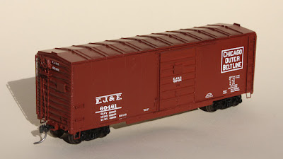
With this destination identified, I then make the waybill below, including a Weight Agreement stamp. The freight car that will carry this load happens to be my newly finished EJ&E box car built from a Sunshine Models mini-kit (for a description of that project, see: https://modelingthesp.blogspot.com/2024/01/sunshine-ej-box-car-mini-kit-part-3.html ).

For background on this waybill design, you can search this blog, using “waybills” as the search term in the search box at the upper right corner of this post; or see one of my published articles, such as Model Railroad Hobbyist (one of my “Getting Real” columns, entitled “Operating with Prototypical Waybills,” January 2018; still available to read on-line or download, for free, at: www.mrhmag.com ).

I hope this single example suffices to illustrate what can be gained from these Shipper Guides. They are particularly valuable when they describe the territory of a truly large railroad like the B&O. I am certainly happy to have this one.

Tony Thompson

Saturday, January 20, 2024

Modeling an SP Class F-125-1 flat car

In an earlier post, I commented on the recent Class One Model Works model of a General Steel Castings Corp. (GSC) one-piece cast body for a depressed-center flat car, and showed photographs of the prototype casting and of a completed SP car (see it at: https://modelingthesp.blogspot.com/2023/10/the-new-class-one-flat-car.html ). 

I mentioned there that Class One is offering essentially two body styles, differing in the end decks, whether they are wood or are screen over the open body casting. But Southern Pacific, as I showed in the previous post just cited, had neither style. Instead, they placed steel plate over the end areas, and also covered the transition areas between end and center decks with steel plate. I decided to see what I could do with the Class One model, and bought one. All I needed to specify was the “square” jacking pads.

The choice of railroad and car number here (SL-SF 3900), of course, is irrelevant, as I was going to modify the model and repaint. As I had surmised, it was quite easy to pop off the wood decks by inserting a razor blade under one edge and working it gently up until the attachment pegs let go.

Now I needed to add representations of the SP-applied steel plate. Below is a detail of the overhead photo from the previous post (see first paragraph, above, for link) showing half the car. It shows that the SP frame casting did not have as many holes in the center deck as the Class One model has. It also shows the minor number of tie-down holes in the end deck.

To model the sheet over the car ends, I chose Evergreen styrene sheet in the 0.005-inch thickness. I wanted the sheet to be flexible enough to readily cover the dropping transition from ends to center. I cut two pieces to the right width and length, then glued one to the end deck only, using canopy glue. (This adhesive does a great job and will not distort or attack styrene.) The idea was to let the glue cure to secure the sheet to the car end first, as at left below, so that it could later be pulled down and glued onto the transition area, as at right.

With both sheets secured, I laid out an approximate set of center lines for two groups of five holes on each end deck (see prototype photo above). I drilled them #75, intermediate between the smallest and largest holes in the prototype photo above.

At this point, I’m ready to paint and letter the car, and deal with the trucks (they are roller-bearing trucks, while SP had solid-bearing trucks). More in a future post.

Tony Thompson

Wednesday, January 17, 2024

Bill Neale: an appreciation

Just last December 28, one of the model railroaders I have admired most passed away. It was Bill Neale, of Farmington, Michigan (in the Detroit area), aged just 74. I know Bill grew up in Indiana, and over his career worked for GM, HP and EDS. He was active in the NMRA and in the Pennsylvania Railroad Technical & Historical Society. For a fuller biography, you can visit this site: https://www.heeney-sundquist.com/obituary/william-neale-ii . I enjoyed chatting with him every time we had the chance. Here’s a good photo from that obituary. 

I first knew Bill’s name because of his article in Model Railroader (“Plastic pocket car cards,” February 2009, pages 62–65), with his idea to use clear sleeves, intended for baseball-card collectors, to hold what are usually called car cards. Bill very appropriately called them waybills.

These waybills were simply inserted into the clear sleeves, which bore labels for individual cars. This meant that the waybills would be about the size of baseball cards, 2.5 x 3.5 inches, plenty of space for generous information (something I like) but small enough to fit in a shirt pocket and easy to handle. I thought Bill’s waybills were a little primitive, but the card sleeve idea really caught my imagination.

Since then, I’ve published several articles about my own waybill design, along with numerous posts to this blog on the topic (easily found by using “waybills”as the search term in the search box at upper right) and often mention that the entire idea and inspiration came from Bill. And as it happened, Bill later revised his own waybills to reflect some of my ideas! Inspiration flowing in both directions.

One of the great pleasures for me whenever there was an operating weekend in the Detroit area was another visit to Bill’s superb PRR layout, modeling the Panhandle Division west of Pittsburgh (I described it extensively in a post about ProRail in 2021, at: https://modelingthesp.blogspot.com/2021/11/attending-prorail-2021.html ). Of course part of the pleasure was to see Bill himself again.

I had earlier shown a few scenes from the layout taken at the GLG (Great Lakes Getaway) in 2017 (see this post: https://modelingthesp.blogspot.com/2017/12/layouts-at-great-lakes-getaway-part-2.html ). Luckily, I attended another GLG just this fall, and saw the layout one more time, along with a bunch of others (see descriptions at: https://modelingthesp.blogspot.com/2023/11/the-2023-great-lakes-getaway.html ).

This was really one of my favorite layouts, among those I like best in the whole country. His depiction of the Pennsylvania Railroad in 1939, in the tri-state area of western Pennsylvania, the West Virginia panhandle at Weirton, and into Ohio at Steubenville and Mingo Junction was beautifully done. Though it’s not a large basement, Bill masterfully designed the layout to include a significant amount of mainline running and some excellent switching areas. 

A centerpiece of the layout was his (necessarily considerably compressed) model of the Penny’s Panhandle Bridge across the Ohio River, connecting Weirton, West Virginia with Steubenville, Ohio. The state line is even marked on the fascia.

The principal yard on the layout was at Weirton, and I have operated there several times, both as assistant yardmaster and (last fall) as yardmaster. Really a nice, spacious yard to work in, and busy enough with substantial train lengths to service. In the foreground, you see a few of his impressive and thoroughly-weathered fleet of gondolas.

These gondolas were mostly well-rusted and dirty inside and nearly every one contained rubble from previous loads. As I know from watching passing trains from overhead, this is quite prototypical, and I think Bill modeled it as well as anyone. Here’s an interior view.

The other extensive switching area was at Steubenville, and on one visit, I drew the Steubenville switch job. This really was challenging and fun, with lots of planning needed for many of the moves. The power was a PRR 0-6-0, seen here passing the depot.

Before closing, I want to add one more comment. When I first met Bill in person, we really hit it off and had a great conversation. Since then, I have chatted with Bill at many meets and have operated on his layout five times, every one a delight. So it was with considerable sadness I heard about his passing. A great guy with a great layout, a mentor and a friend. I’ll miss you, Bill.

Tony Thompson

Sunday, January 14, 2024

Sunshine EJ&E box car mini-kit, Part 3

In the first post in this series, I showed the beginning steps in assembling a Sunshine Models “mini-kit” for an EJ&E box car, a distinctive car built in 1941 with 10 ft., 6 in. inside height and 8-foot panel doors. The kit supplied resin ends, doors and side sills to match the distinctive original. You can read that post at this link: https://modelingthesp.blogspot.com/2023/12/building-sunshine-mini-kit.html .

In the second post, I completed assembly of the basic model (except for a few details left for final work, such as sill steps and running board, which I almost always install last), and gave it a coat of primer. I described all that work as far applying the coat of the primer in that second post (see it at: https://modelingthesp.blogspot.com/2024/01/a-sunshine-mini-kit-part-2.html ). That brought me to the choice(s) of paint scheme. 

One choice would be the original boxcar-red scheme, which is how the cars were built. The photo below is an in-service view from the 1940s (George Sisk photo, Joe Collias collection). Note that EJ&E placed its repacking stencil to the left of the car door, above the side sill.

But there is a second choice. Starting in 1953, EJ&E sent 409 of the original 500 cars back to American Car & Foundry for refurbishing. What that work comprised is evidently not known, though the external features remained the same. But the appearance was quite different, because a new all-green paint scheme was applied, with orange lettering. That scheme was shown in an AC&F photo in an article by Ed Hawkins in Railmodel Journal, “Modeling Modified 1937 AAR 40-Foot Cars, Part II,” Vol. 8, pp. 8–13, October 1996.

The green scheme is very attractive, and was one of the early examples of railroads moving away from very plain paint schemes,which many did during the 1950s; but since I model 1953, it’s a toss-up whether I really want to operate this brand-new paint scheme, or rely on the original EJ&E lettering. I have decals for both, so really was torn in making this decision.

Finally I decided to go with the original scheme. I used the nice Rail Graphics decals provided in the mini-kit. Below you see the model at this point, with kit trucks and Kadee #58 couplers, but with the running board yet to be installed. The Hawkins article lists the running board as Apex Tri-lok, helpful to know since that isn’t visible in any of the prototype photos I’ve seen. Kadee makes a superb version of this running board, which I will use.

Next the Kadee running board was installed with canopy glue, and an overall coat of clear flat (I prefer Tamiya TS-80 for this) was applied in preparation for weathering. My usual acrylic wash technique was used to weather the model (for description of the process and examples, see the “Reference pages” in the upper right corner of this and every post). Finally, I added some chalk marks with Prismacolor white and gray pencils, and route cards.

I have enjoyed this particular project, really an advanced kitbash of a Branchline kit with resin parts from Sunshine Models. This car will be going right into layout service. But its first public viewing was at Cocoa Beach earlier this month, in the Prototype Rails display area (for more on that, see: https://modelingthesp.blogspot.com/2024/01/cocoa-beach-2024.html ), along with two other freight cars of mine.

Tony Thompson

Thursday, January 11, 2024

Cocoa Beach 2024

Yes, it’s that time of the year again, early January, and one of my favorite events, the  Prototype Rails meet, was held once again at the Hilton in Cocoa Beach, Florida. This was the 23rd renewal of this event, and I have attended all but one. The late Mike Brock ran this event for nearly all those years. Now his one-time deputy Marty Magregian has taken over, and it ran as smoothly as it did under Mike.

Once again, it was a delightful meeting, primarily a gathering of the freight car community, and I know many of the modelers who attend. This year there were 210 attendees, along with 25 last-minute cancellations due to illness, an unusual proportion.

As is true for me at most meets like this, the clinic program is my core priority. I did give a talk myself, but will have to say that the program this year, assembled as always by Jeff Aley, was really outstanding, with many excellent talks. There were a few late scratches, but most of the program went off as advertised. One person we were all delighted to see giving a talk was Tony Koester, giving an update on his layout. Here he is with his opening slide.

A close second in my regard is the huge model display. As always, there were really a lot of terrific models exhibited. One of the ones I really liked (and was impressed with what it took) was Fenton Wells’ Birmingham Southern box car. This was a 1937 AAR box car body, 10 feet inside height, but with a PRR-style flat roof and flat plate ends. Fenton built it from an IMWX box car kit, with a Red Caboose X29 roof, and an end made by filing the kit end flat and adding Archer rivets. Decals are K4.

Another model I liked was one of Bill Cialini’s modern cars with well-executed weathering and graffiti. This covered hopper, well paint-patched from a previous owner, is a good example.

As is true every year, most of the ballroom is filled with vendor tables. This is a wonderful chance to see new products or smaller vendors who you might otherwise not know about. And between all clinic sessions, a good crowd was taking advantage of the opportunity.

One striking vendor display was by 3D Central Trains, showing a huge range of 3D-printed parts, as you can see below (for more on what they do and what you can buy, go to: https://3dcentraltrains.com/ ).

For just a single example, below is the underbody for a 60-foot woodchip car, showing the way that underbody brake parts can be printed in one piece. (You can click on the image to enlarge it if you wish.)

Their representative did say that they prefer not to print grab irons and ladders, as they are difficult to make scale size and even if achieved, would be quite brittle. But everything else looks great. And as I’ve been saying for some time (see for example this post: https://modelingthesp.blogspot.com/2023/11/more-amazing-3-d-printing.html ), I believe this is just the thin end of the wedge in the future of our hobby.

A great meet, one I always look forward to, and always enjoy. If you, dear reader, have never been to Cocoa Beach for this meeting, I strongly suggest you consider it next January.

Tony Thompson

Monday, January 8, 2024

Other railroad documents

I have written blog posts about quite a few items of prototype paperwork, both about waybills and associated documents used in the movement of freight, and operating documents such as train orders. In the present post, I want to show a few more, which could readily be adapted for model use if desired. Three of the documents I show today are from the collection of Michael Litant, whose generosity in sharing these is appreciated. 

First is an interesting form, used in the movement of oversize loads which might require idler cars. It’s a Boston & Maine document and is 4.25 x 9.5 inches in size, barely fitting on a route card board and perhaps more likely on a placard board. It documents a New York Central gondola, NYC 726484, a 65-foot car with a steel floor, with a load of plate steel, 104 feet, 10 inches long. This meant that an idler car was used at each end, B&M 34015 on the east end, and EJ&E 6545 on the west end. Both were 53 ft., 6 inch flat cars. As the form shows, the overhang at each end of the gondola was approximately equal, about 24 feet in each case.

Note in the above form (you can click on the image to enlarge it) that the corporation is shown as “debtor,” and the trustee, Robert W. Meserve, is named. The B&M declared bankruptcy in 1970; the form is dated May 25, 1975.

I have shown several times examples of prototype Empty Car Bills, and here is yet another example, this one from the New Haven. Though not filled out, it evidently originated at the Roxbury, Mass. yard, as it is so stamped. It is 4 x 9.25 inches in size. Like many such Bills, it can be used to move an empty car to where it is to be loaded, or can move an unneeded empty car homeward. Interestingly, space is including in this bill for grading of the interior condition of the car.

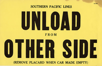
I recently was given this familiar placard, seen on many railroads though often on manila rather than yellow card stock. Since it reads “Southern Pacific Lines,” it is likely from before 1946, when SP changed both its car lettering, and most company documents, to remove the word “Lines.” Soon after 1946, most such documents began to labeled “Southern Pacific Company.” It is 7 x 11 inches.

Another Litant item, that is more of an operating detail document, is a classic “train delay” form, used on many railroads to report, as it says at the top, “Extra Time Claimed by Conductors and Trainmen for Switching, Terminal Delays and other Arbitraries.” It’s a New Haven document and is dated March 14, 1963, and was deposited at the Readville, Mass. freight agent by J.E. Bergeron, conductor, along with two brakemen, J.J. Morrisseey and J. Beale. It’s 5.5 x 11 inches.

What’s interesting here is the reason for delay (one hour claimed). It reads, “Assisted wrecking crew to re-rail car # TNO 60790 [a 40-ft. steel box car] which was derailed by consignee at Norwood St. house while barring cars down.” Likely “barring” refers to using a pry bar or crowbar to move a car, by prying under the wheel and lifting. One of the classic aspects of this document is that I’ve heard more than one conductor talk about documenting delays, and saying “we filed a green sheet,” or “we grabbed a greenie right away.”

Asking a crew on a model railroad to fill out a “green sheet” would be a little idle, as we are rarely paid for our operations. But the oversize-load document could well be included along with other normal waybills as part of a train. Regarding this particular oversize-load document, presumably the load in the NYC gondola had its own waybill, but this kind of document could be supplied also.

I continue to enjoy coming across prototype documents like these. Not only are they interesting as railroad artifacts, they are glimpses into operating procedures, and in many cases could certainly be adapted for model use.

Tony Thompson

Friday, January 5, 2024

A Sunshine mini-kit, Part 2

This thread is about a mini-kit provided by Sunshine Models at a Naperville meet at least ten years ago, that I discovered among other kit boxes. It provides replacement resin parts for a Branchline Postwar box car, to model one of the EJ&E 1941 box cars with 8-foot doors. My introductory work, and some prototype photos, are in the first post of the series (see it here: https://modelingthesp.blogspot.com/2023/12/building-sunshine-mini-kit.html ). 

In the preceding post, I showed attachment of resin ends and doors to the Branchline body, along with addition of car weights and the roof. I also removed the original “tabbed” side sill. Thus the next step on this project should be attachment of the new resin side sills. But to make sure it would be compatible with the kit underframe, I decided to work on that first.

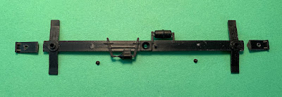
Now the mini-kit provides resin parts to completely re-do the underframe, including cross-bearers to match the door width. But a little experimentation showed me that these underframe components, though permitting a correct prototype underframe, nevertheless would be all but invisible with the car on the track. Since, like most of freight cars, the primary destination of this model is on-layout operation, not contest entry, I decided I would go with the Branchline underframe.

Once the kit underframe is attached, the new resin side sills can be securely installed, using canopy glue along the seam, and to attach to the bolster ends. The view below shows whys the underframe is minimally visible from the side: the depth of the side sill under the door area completely obscures it. By the way, bolster screw holes have been tapped 2-56.

One point I should make is that these side sills are quite thin. That’s good for appearance and for fitting to their location. But I soon discovered that they flex alarmingly when handled. I decided to add some supports behind them, and chose Evergreen #8608, scale 6 x 8-inch styrene strip, installing short pieces with canopy glue. This made them substantially stiffer. 

Next I could begin to add kit details. On the car sides, these are straightforward to do, but the ends have none of the holes ready for acceptance of detail parts, and in addition the usual styrene cement for adding styrene details to a styrene body won’t work. I decided to use canopy glue on the ends. But I began by adding the side ladders, because the end ladders must have rungs in line with the side ladders.  The A end is shown below.

The same process was followed with the side and end grab irons, with the grab iron on the end aligned with the lower one on the car side. The handbrake shown in the prototype end photo (see previous post, link in top paragraph, above) resembles a 5-spoke Ureco, and I was able to find such a brake wheel and gearbox in my parts box.

On the B end, I made sub-assemblies of the styrene parts, such as the brake step and the handbrake mount, using styrene cement, so that the assemblies could then be attached with canopy glue. The grab irons on the end sills were made from 0.015 styrene rod, attached with canopy glue. Only the sill steps (which I usually apply last), and a running board,  remain to be applied on the basic body.

With the body assembled, including Kadee coupler boxes, I gave the model a coat of primer. I used Tamiya Fine Surface Primer (Oxide Red).

I will suspend description at this point, in favor of other projects, and will return to this model in a future post.

Tony Thompson

Tuesday, January 2, 2024

Reconditioned PFE car, Part 2: model

From 1935 to 1941 or so, Pacific Fruit Express “reconditioned” (that is, minimally upgraded and repaired) more than 7600 older cars with 30-ton underframes (and a few 40-tonners). They were classed R-30-9 (or R-40-9) when completed. I gave some background on these cars in the preceding post (you can consult it at: https://modelingthesp.blogspot.com/2023/12/the-pfe-reconditioned-wood-cars.html ).
I am building a Red Caboose kit for one of these cars, as I mentioned toward the end of that previous post. Most of my kit assembly is according to the kit directions, so I won’t go into it here, and nearly all of the kit details are fine. An important and quite visible exception is the ice hatch arrangement, which is what I showed in that previous post, with wood hatch covers and  replacement hatch cover hinge supports and striker bars.

To continue: one thing I do with models of most house cars: insert weights inside. I usually use 5/8-11 steel nuts. Together, these weigh about two and a half ounces. I attach them with canopy glue, which has proven itself over the years to provide a secure and dependable attachment of these heavy objects inside models. In this photo, you can see that I’ve added the side and end details.

I would just note that these nuts cost 69 cents each at my local hardware store, $1.38 together. Comparable stick-on commercial weights, for the same amount of weight, cost about $5.00, and I have had the stick-on adhesive fail in some cases. Canopy glue has never failed in my models.

Once that is done,  I proceeded with the underframe. The kit supplies a K brake system, which in fact most of the Class R-30-9 cars, when reconditioned, did retain from their original construction. Many of these cars were rebuilt again in 1949–1950, and at that time some cars were upgraded to AB brakes. But since so many photos from the early 1950s do show K brakes, I decided to apply that system to this car.

Second choice to be made is couplers. As is my practice, I substituted Kadee whisker couplers in the kit coupler box, but I drilled out and tapped the box 2-56. The view below shows the completed underframe and floor, attached to the car body, and with the Kadee couplers installed (the brass screw heads will of course be painted). Sill steps remain to be installed. Usually I do not add the drain chutes, which are all but invisible.

The third point to consider is trucks. The kit supplies T-section trucks, a type very commonly retained on reconditioned Class R-30-9 cars; but the Red Caboose version of these trucks is simply sub-standard. I replaced them with a pair of Kadee “HGC” T-section trucks, Kadee part 1572. Again, I tapped the truck screw hole 2-56.

Withe the underframe complete and attached to the car body, I needed to choose a car number. I felt it should be well under PFE 95736, after which all reconditioned cars were given steel hatches, and not too close to the original car, PFE 91022, as the earliest cars kept ice hatch platforms. I chose PFE 93461. Here is the re-lettered model, ready for weathering.

Since the paint scheme of the model is one that was in use from 1946–48, by my modeling year of 1953, it might be fairly dirty — keeping in mind that PFE did wash its cars frequently in this period. I also wanted to include the appearance of a workman having wiped the dirt from the car number for better visibility. Weathering was done with my usual acrylic wash technique (see link to “Reference pages” at upper right corner of this post).

Note above that I have also added chalk marks and route cards to the car.

This concludes work on this model, another addition to my considerable fleet of PFE cars. And with six shippers on my layout who use reefers, they are all useful in layout operating sessions!

Tony Thompson