This is an old topic in model railroading, so I will be brief, but I think there are important points which deserve repeating.
Most of us do build layouts primarily for ourselves, and that’s often stated if any aspect of a layout gets criticized. Of course we have modeling friends and perhaps an operating group, and knowledge of those folks’ perspective will affect what we do and how we do it. And it is natural to regard these layout viewers as the “expert” audience. But I think in a number of ways, the real test comes when the layout is viewed by what one of my friends calls “civilians,” people with no particular knowledge of the hobby.
I know from having shown my layout to neighbors, friends and relatives over the years, that such visitors indeed do not know very much about any prototype railroad, and so could accept just about any railroad equipment they might see. But they have a surprisingly good sense of era. They do grasp if your era is the 1930s or the 1950s or the 1970s, partly by motor vehicles, partly by signage, partly by the clothing of figures. And they do notice anomalies within those eras, such as a girl in a miniskirt in a 1940s layout scene, or a 1980s minivan in a street scene from the 1950s. I remember visiting a layout set in “the present,” and I heard another visitor, not a modeler, say, “How come there are no graffiti?” And they readily notice out-of-era logos for familiar consumer products, for example on billboards, that are too modern or too old-fashioned.
So would I advocate that all you need to do is be “scenery consistent” in developing a layout? Not entirely, no. Those same “civilian” visitors will notice an unweathered freight car in a train of weathered ones. They will sure notice an unpainted brass engine (though they may find it more impressive looking than your painted and weathered ones). On a pre-1955 layout, which means nearly all freight cars will be boxcar red, or black, or yellow/orange reefers, they will sure notice any brightly colored cars (a few, of course, are prototypical). And they will probably notice steam locomotives mixed with modern wide-nose diesels
This leaves to one side the more flamboyant examples of freelancing. I vividly recall an NMRA convention at which one model entry was a trio of Model Die Casting ore cars, somewhat upgraded in details, but painted lime green, lettered for the Jimmy and Suzy Railroad (the entrant’s children, as he proudly explained), and of course entirely unweathered. I believe your average visitor will recognize that models of that type do not represent part of the real railroad world.
But even with nominally realistic modeling, issues can arise. In thinking about my hypothetical visitor to your layout, whether a modeler or not, you may well think, “Hey, I can explain.” Sometimes that is natural. Yes, the MKT really did have yellow box cars in the 1940s and 1950s, and so forth. But I maintain that every time you have to explain something, you are losing some of the plausibility of your layout that you have (presumably) worked pretty hard to achieve.
That is the core point I’m trying to make in this post. Be as consistent and “mainstream” and “average” in your modeling as you can, consistent of course with your particular prototype era and location. That’s the basic reason I try to avoid modeling very many rarities or oddballs, whether rolling stock, or automobiles, or billboards, or structures, or anything.
But as I mentioned above, many modelers think of their primary audience as the fellow modeler who knows something about the railroad being modeled, especially for the era which has been chosen for the layout. Now the things that might call for “explanation” are more specialized.
A number of modelers, including my friend C.J. Riley, have placed photos, drawings, or other materials on the fascia about the layout, to silently document what is seen to be modeled nearby. Then the modeler can say to himself or herself, “Oh, this model packing house really looks like its prototype,” or whatever the case may be.
These same considerations are part of what made me change my former layout, conceived as an imaginary short line, the Lompoc & Cuyama, which interchanged with the Southern Pacific, into an SP branch line. I discussed this in a post about my choice of layout locale (you can view it at this link: http://modelingthesp.blogspot.com/2011/01/layout-design-locale.html ). The branch line itself is still imaginary, but the Southern Pacific, and the area of California modeled, are real.
Best of all, it seems to me, is if the knowledgeable visitor, likely a fellow modeler, walks into your basement or layout room and says, “Ah, Hinton!” or “Oh, it’s the Oakland Mole,” or even “Hey! Sherman Hill!” Ideally, they would then go on to observe further, something like “I see it’s 1940” or whatever corresponds. You have not had to “explain” anything, because your modeling speaks for itself.
Chuck Hitchcock in Kansas City used to have a fine layout (now replaced) which modeled the transition-era Santa Fe in Kansas City and environs. [See Kalmbach’s Great Model Railroads, 1991.] I have heard Chuck relate how, when Richard Hendrickson visited for the first time, he walked into the layout room, where about the first thing you saw was the Kansas City depot. Noticing the train standing there, Richard promptly said, “Fast Mail, 1951,” and as Chuck said, sounding a little surprised, “He got it right, too.” I think many of us wish for both those things: a layout which is that accomplished in place and era, and a visitor who can appreciate what we have done.
Tony Thompson
Friday, June 28, 2013
Tuesday, June 25, 2013
PFE’s Western Pacific cars
Having posted my comments about a “what if” Rock Island car in the PFE fleet (you can see it at: http://modelingthesp.blogspot.com/2013/06/a-pfe-what-if.html ), and having mentioned that Rock Island wanted to obtain terms similar to those of Western Pacific, I received a couple of questions about how the WP arrangement worked. This topic is fairly well developed in the PFE book (Pacific Fruit Express, 2nd edition, A.W. Thompson, R.J. Church, and B.H. Jones, Signature Press, 2000), and I will only summarize here.
In 1922, Southern Pacific was endeavoring to prevent the Central Pacific part of the railroad from being divested by court order. As part of an agreement before the Interstate Commerce Commission, SP negotiated several agreements with Western Pacific, though the Commission had imposed no conditions on SP regarding the WP. One of these was the famous joint-trackage agreement across Nevada. Another was a contract between WP and PFE, to incorporate WP-owned refrigerator cars into the PFE fleet. These cars were built to PFE blueprints, and were to be entirely operated and maintained by PFE. PFE paid a fixed monthly charge to WP, and in turn collected all mileage payments resulting from operation of the cars. Any repairs or upgrades to the cars beyond routine maintenance would be done by PFE and billed to WP.
The contract between WP and PFE specified that WP would provide enough cars to carry its proportional share of the total PFE perishable traffic. In 1923–1924, this was computed to be 2775 cars. PFE already owned about 36,000 cars at this time, so the WP contribution was 7.7 percent of that total. This fits with SP estimates, which concluded that WP’s traffic volume across Nevada at the time was little more than 5 percent of SP’s traffic on that route. The WP cars were numbered PFE 50001–52775.
There are two observations to be made about modeling WP cars. First, there has long been a “tradition” to decorate models of the WP PFE cars in yellow instead of PFE orange. In fact, the WP cars were never different in color from the rest of the PFE fleet. When new, the WP cars were a color close to Armour Yellow, as were all other PFE cars at that time. In 1929, when PFE adopted Light Orange to replace yellow, WP cars were repainted in the new color right along with all the other PFE cars. (This color was later chosen by SP as part of the color scheme of the Daylight trains, and today is best known as Daylight Orange.)
The second idea one hears from modelers is that the WP cars were preferentially returned empty to WP for loading by Western Pacific customers. It is clear from my interviews with retired PFE employees that there was certainly no policy to do that, nor could it have been very common. The whole PFE fleet was operated as a single fleet. The WP cars could be loaded anywhere, as could the regular “SP-UP” cars. I can understand that WP modelers like to see WP reefers in their trains, but they should be no more numerous than the percentage of WP cars in the PFE fleet.
By 1938, PFE was rebuilding its huge fleet of Class R-30-12 and -13 cars to more modern standards. In particular, the PFE rebuilds received steel-framed superstructures. The WP cars equally needed rebuilding, so PFE requested the funds from WP to do so. Western Pacific, chronically short of money, declined, and the WP cars instead were “reconditioned,” meaning that they got new wood-framed superstructures, instead of steel. Unfortunately, this meant that the remaining service life of the cars was sharply reduced. The wood framing was only expected to last eight years or so, in contrast to the 15 to 20 years PFE expected for its steel-framed cars.
By 1950, less than 1000 of the WP cars remained in service; most of the original 2775 cars had been scrapped (or returned to WP for use in company service). The remaining cars in service were substantially deteriorated by this time, and in late 1952 PFE recommended that they be given solid steel roofs and Dreadnaught steel ends, as PFE was applying to its own rebuilds. Once again, however, WP requested a minimum-cost project. This time the cars did get steel-framed superstructures, along with car fans, and were renumbered as 55001–55899. This work was done during 1952–1953.
With less than 1000 WP cars at the time I model, I need a maximum of one of these cars in my fleet. That reflects my modeling strategy for PFE, to model one PFE car per 1000 prototype cars, as a simple way of obtaining a realistically proportioned model fleet. (I discussed this idea in a prior post, which you can see at: http://modelingthesp.blogspot.com/2010/12/choosing-model-car-fleet.html .)
As a 1953 modeler, I could choose to model either a 50,000-series reconditioned car or a rebuilt 55,000-series car. I chose one of the older cars. Since evidence indicates (see the PFE book) that about the first 200 cars purchased by WP had the Bettendorf single-beam underframe (characteristic of PFE Class R-30-12), the Red Caboose kit with that underframe should have a number within the first 200 WP cars. Red Caboose is well aware of this and has numbered their kit cars in accord with that. (The remainder of the WP fleet appears to have had what PFE called a “built up” underframe, the same as PFE Class R-30-13.)
Building the Red Caboose kit is straightforward and needs no commentary. Changes I made: I installed Kadee no. 58 couplers in Kadee boxes, attached with 2-56 screws; added Reboxx wheelsets in the Accurail sideframes supplied by Red Caboose in the kit; and used my usual car weights, which are a pair of 5/8-inch steel nuts (attached with canopy glue which, if you don’t know about it, I’ve described in a prior post; you can view it at this link: http://modelingthesp.blogspot.com/2013/05/a-few-words-in-praise-of-canopy-glue.html ). You can see these weights below, along with my painting of the inside of the car sides black, which minimizes any translucence of the orange plastic body molding.

The car body rests in my simple work cradle (you can read about it at: http://modelingthesp.blogspot.com/2013/05/a-working-cradle-for-model-freight-cars.html ).
With construction complete, I proceeded to weather this car, using my normal procedure with acrylic washes, using a mixture of Neutral Gray, Burnt Umber, and Ivory Black. With weathering complete, I added a patch of fresh paint and a reweigh location and date, in this case TUC 9-50, meaning the PFE shop at Tucson. Here is the car being spotted for icing at Shumala by Consolidation 2829. Some will recognize the engineer’s cigarette as locomotive rebuilder Al Massi’s signature detail. (You can click to enlarge the image.)

Delivering ice to the icehouse at right is the Ice Service car described in a previous post, http://modelingthesp.blogspot.com/2013/06/ice-service-refrigerator-cars.html .
With modeling work complete, this WP car joins my PFE fleet, an interesting detail among all the cars with SP and UP medallions, but carrying perishables just like all the others.
Tony Thompson
Saturday, June 22, 2013
Waybills, Part 29: Waybill Preparation
An old friend of Tony Koester’s, Harry Dolan, retired recently from Norfolk Southern management. His career ranged widely across NS territory, and included working on parts of the former Nickel Plate, Wabash, AC&Y, W&LE, N&W, Interstate, L&N and Southern. His time on the former NKP (including working the Yard Clerk job at Lafayette, Indiana, and supervisory work at Frankfort, Indiana), is especially interesting to Koester, since Harry’s recollections of his experience naturally provide core information for how the freight car paperwork for Tony’s layout should be managed. But even if you’re not interested in these specific NKP details, there is rich information here for all of us. I believe that for anyone interested in prototype waybills, this is a superb summary.
In what follows, I quote, with Harry’s permission, an excerpt from one of his narratives about the waybill process, which I think vividly illustrates how things were done. Any material in square brackets was added by me, mostly for clarity.
“Perhaps an explanation of how waybills, the 8-1/2 x 11, paper versions, either Revenue, or Non Revenue, are generated in the Agent's Office will help. Let’s take the Frankfort [Indiana] Agency (I hope I can remember all the numbers from 50 years ago) as an example. The Frankfort Agency had three series of waybills. Each series of waybills was maintained on a post binder. The post binder had a heavy, cloth-covered, cardboard back with two vertical, 1/8" diameter, steel posts at the top. The binder cover was of similar material, with a slotted, stamped metal latch, that engaged the steel posts.
“Each [of the three] series of waybills had a different waybill number series. For example, Frankfort maintained General Freight (Merchandise) series waybills and assigned waybill numbers starting at 300000 and ran continuously year after year. Because of Ralston Purina, Frankfort also maintained a Transit (grain milling in transit) series of waybills and assigned them waybill numbers starting at 250000. The third series of waybills at Frankfort was the “Non Revenue” series of waybills which were assigned, say, waybill numbers starting at 190000. All series ran continuously and [when complete] were bound up with string, 1000 waybills at a time.
“Other agencies might have other series of waybills. For example, the ore dock agency at Huron, Ohio, had a separate series of waybill numbers for Iron Ore. The specialty (Transit, Iron Ore, Coal & Coke, Set-up Automobiles, etc.) series waybills, quite often had special preprinted, multi-part, waybill forms. However, General Freight and Non Revenue Waybills were both typed using the same, eight-part, standard waybill form.
“So let’s “bill” (waybill) a few cars. First [one] is a box car load of corn being shipped by one of the grain elevators downtown, and the process begins with the elevator manager dropping off a Bill of Lading, or more properly a “shipping order” at the railroad, or the agent picking it up at the elevator. The first action on the part of the railroad is for an agency employee to sign (actually hand sign the agent’s name) all copies of the Bill of Lading, and return all but the shipping order, to the elevator manager. Next a railroad, date/time stamp is placed on the shipping order and it is ready to go to the bill clerk.
“The bill clerk places a standard, eight-part, blank waybill form in his typewriter, lifts the top cover of the General Freight series waybill file to get the next waybill number, and begins typing. When he comes to the block reading “Waybill Number” he assigns the next number in the General Freight series, and continues transcribing the information on the shipping order to the waybill. By the way, in that little square box just to the right of the Car Initial and Number, marked “Kind” [of car], the clerk will type the capital letter B, not XM.
“Once the typing is done, the waybill will be removed from the typewriter, laid flat on the desk, and, while the thumb and fore finger of the left hand hold the top of the waybill form, the right hand is used to jerk the top two copies from the eight-part form. The top copy (original) goes to the “Industry” bill box at the Eastbound yard clerk’s desk so the waybill can be mated with the car when the “Commercial Engine” [switch job] drags the load of corn back into the yard that afternoon.
“The shipping order is then placed behind the second copy of the waybill, a two-hole paper punch is used to punch two holes in the top of both the copy of the waybill and the shipping order, and both are placed [on the posts atop] the General Freight series waybill file. The remaining six copies, and the carbon paper are discarded. [A few kinds of shipments could require use of more than two copies of the waybill, for example, if a waybill copy is sent by U.S. Mail to the destination agent, so he can notify the consignee of impending arrival.]
“Next, the General Foreman’s clerk drops off a shipping order for a flat car load of freight car wheels on the RIP Track at Frankfort, [which is] being shipped to the Mechanical Department, at Bellevue [Ohio]. In this case, the shipping order is not signed, but all copies are date/time stamped, before the “Agent’s Copy” is sent to the bill clerk. The bill clerk again puts a standard, eight-part, waybill form in the typewriter, but this time he opens the “Non Revenue” series waybill file, and assigns the next “Non Revenue” waybill number. The bill clerk will then complete the waybill the same as he would do for any other load, except when he gets to the space reserved for Freight Charges, he will enter, “Co Matl Free” (Company Material Free).
“As with the revenue waybill for the car of corn, the top, or original copy, will go to the Eastbound yard clerk, the second copy and the shipping order to the Non Revenue waybill file, and the carbon/balance of copies to the trash.
“Next, let’s bill an empty GACX covered hopper being released by Mars Candy Company. In this case Mars Candy notified the Frankfort Demurrage Clerk they were releasing the GACX covered hopper car, empty. The first thing the Demurrage Clerk will do regarding disposition of the empty car, because it is a private ownership car, is check the inbound waybill to see if the car is leased to anyone. In this case the inbound waybill noted that the car is leased to Domino Sugar Company, hence the Demurrage Clerk will check his file for any letters, or instructions from Domino Sugar. If he finds instructions from Domino Sugar he will note the time and date the car was released and forward a copy of the instructions to the bill clerk.
“If no instructions have been received by the time the car is released empty, a copy of the inbound waybill is made, a notation reading “Released Empty (date/time) - Return Reverse Route” placed on the copy of the inbound bill, and this, in effect, becomes a shipping order which is forwarded to the bill clerk. The bill clerk again places a standard, eight-part waybill form in the typewriter, and opens the “Non Revenue” series waybill file to get the next Non Revenue waybill number to assign to this waybill.
“[On this waybill] the shipper is shown as “Agent NYC&StL, Frankfort, Indiana” and the consignee is the original shipper and location of [loading the] car. In the “Contents” portion (lower left corner of waybill), the bill clerk will type, “1 Empty Covered Hopper, L/C (last contained) Granulated Sugar NOI (Not Otherwise Indexed), Returning Reverse Route.” In the Freight Charges column, he will simply type the word “FREE.” In this case the car will follow the exact reverse route, including all junctions, back to its origin.
“For other empty cars, the cardboard, Empty Car Slip (NKP term), Form 667, is the only paper work required for the car to move on the NKP, and was not attached to any other paper work. This form is filled out by the yard clerk.”
To me, this is a fascinating, detailed look at the process, at least as it was done on the Nickel Plate. It would be very interesting to know how similar the process was on other railroads (probably pretty similar, except maybe for nomenclature). Harry has said that these procedures were pretty much the same, in his experience, on the WAB, ITC, AC&Y, N&W, L&N, and SOU, in addition to NKP, indeed differing only in terminology, and it would be interesting to range farther afield. But this account stands on its own as a valuable insight.
Tony Thompson
Wednesday, June 19, 2013
Modeling storage tanks
I have built storage tanks for several of my on-line industries, and need to add more. This post is an introduction to what I have been and am doing. In this first post, I discuss two scratchbuilt storage tanks.
Scratchbuilt tanks are not difficult, and I have done several in the past. Today, with Archer rivets, these are not so challenging. In past years, I have made tanks with simple cores such as plastic pipe or toilet paper rolls, with overlays of 0.005-inch styrene, embossed with rivets. There are also other cylindrical objects which can be similarly converted to storage tanks. For example, I used a white glue bottle for this fuel storage tank.

This interior view shows that I used the top half of the bottle, with the spout cut off.
To make this into a storage tank, I just used the styrene overlay method with embossed rivets, and painted it black. Southern Pacific often put their medallion on oil storage tanks, so I did the same, using a freight car decal.

The ladder at left is simply brass ladder stock, folded so the stile is at right angles to the rungs. (You can click on the image to enlarge it.)
On the top, I added an access hatch (modified from a left-over ice hatch from some kit), a vent, and ladder top rails, bent from flat brass wire. I also added some spillage around the top.

How big is the capacity of this tank? it is 17.5 scale feet in diameter and 23.5 feet high at the outside. The formula for volume of a cylinder is simple, and I have posted how to apply this with tanks previously (the post is available at this link: http://modelingthesp.blogspot.com/2012/10/naperville-tank-car-handout-part-2.html ). In my formula, all dimensions are converted to scale inches, multiplied out in the formula to give cubic inches, and then divided by 225 (converting cubic inches to gallons). This tank would hold 43,400 gallons, equal to the contents of more than three of SP’s standard 12,500-gallon tank cars.
How fast would this gallonage be consumed by steam locomotives? Tenders behind SP steam, in the size range from 7000 to 10,000 gallons of water, had fuel oil capacities of 2900 to 3100 gallons. Looking at some typical oil consumption figures from different parts of the SP, I conclude that a round trip on my (mythical) SP branch line would use less than half an oil bunker. Of course the bunker would be filled before each run, but probably in the amount of about 1000 gallons. So I will only need to deliver company fuel oil to this tank about every other week.
Another scratchbuilt tank I made was kind of a response to a skeptic. I had idly remarked that toilet paper rolls were not a bad size for storage tanks, and a listener said that since those rolls were pretty flexible, he doubted I could make a tank out of one. So of course I went ahead and did it.
I decided to make a horizontal tank. First, I made supports from quarter-inch balsa wood sheet, and painted them concrete (a little too gray a color, though). The curved parts were made, of course, to have the diameter of the toilet paper roll.

Then the tank body received the same styrene overlay with scriber-impressed rivets, both around the tank and on the ends. They aren’t great rivets, but as long as they are not at the front edge of the layout, they do the job.
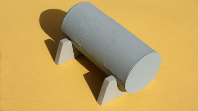
The tank is dark gray for the time being, and will probably be repainted to match the other tanks of whichever one of my bulk oil dealers eventually receives this tank.
These are pretty simple tanks, but they illustrate what can be done, even without using Archer rivets. In a future post, I will describe how I have used Archer rivets for making tanks. Of course there are also lots of kits for all kinds of tanks, and I will talk about those in the next post on this topic.
Tony Thompson
Sunday, June 16, 2013
Ice service refrigerator cars
Many owners of refrigerator cars assigned a few old, worn-out ones to ice service. Ice service was the transportation of ice from places it was produced, to smaller ice houses which didn’t have ice manufacturing capability, which then simply stored the ice for later use.
Pacific Fruit Express was no exception, and in fact maintained a number of cars in ice service. As explained and illustrated in Chapter 13 of the PFE book (Pacific Fruit Express, 2nd edition, Thompson, Church and Jones, Signature Press, 2000), PFE had separate listings for Ice Manufacturing and Ice Transfer plants. Many of the latter were commercial ice companies, such as Union Ice and many other companies, but a few were small enough to need ice brought in by means of ice service reefers.
In addition, when ice got a little short at facilities serving a heavy harvest, additional ice could be moved to those facilities with the ice service cars, usually from PFE’s own Ice Manufacturing plants, but sometimes from commercial ice companies.
We know from several sources that PFE lettered its ice service cars just like all the other cars, except for the added legend ICE SERVICE, in 9-inch lettering in place of the usual PACIFIC FRUIT EXPRESS legend above the reporting marks. This lettering has been provided in Microscale set 87-501 for years, so you can letter any kind of PFE car with those decals, and obtain an ice service car.
Recently Red Caboose re-ran its PFE R-30-9 model reefer in Ice Service lettering, which appears to be entirely correct. This is my lightly weathered version of the ready-to-run model.

This is the style of PFE lettering after early 1952, when lines above and below reporting marks and numbers were omitted, along with periods in “PFE.”
I will add a comment about weathering. There is a tendency among modelers to weather ice service car models heavily, and it’s true these were probably rarely washed; but they did get repainted from time to time, as part of car upkeep, so a relatively recent paint job like the model shown above is entirely appropriate. For photos of cars like this in service, see page 154 of the PFE book.
There is another kind of ice service car, which some railroads used to deliver ice to section houses, homes of signal maintainers and others, and many depots (before the days of widespread refrigerators instead of ice boxes in homes). Ice might also need to be delivered to stations at which passenger equipment needed to receive ice, usually for ice-activated refrigeration, but also for dining car kitchens. Among them was SP, and they bought old PFE reefers from time to time, and then used them for this delivery service. This is shown in Chapter 4 of Volume 4 in my series on Southern Pacific Freight Cars.
Among the SP company ice service cars were some elderly cars which had been classified as Class R-30-2 on the PFE, and were retired by PFE in the 1930s. The SP bought ten of them. As with most other SP ice service cars, they were painted boxcar red and given SPMW lettering.
Some years back, I built one of the Westerfield resin kits for those early PFE Class R-30-2 cars, so I could represent one of the ten that were purchased for SP company use. Here is my version of the lettering on one of these cars.

Just one word of caution: these kinds of ice service cars would rarely be interchangeable. That is, the PFE cars would not be in use for SP company delivery, nor would the SPMW cars be employed by PFE to move ice around. So having both kinds introduces still more operational variety.
In summary, Ice Service cars provide a variant kind of refrigerator car operation, for those interested, and even if you don’t model an icing facility, you can still move ice cars like the PFE ones in mainline trains, en route to someplace that is short of ice. And of course company-service ice cars like the SP ones can go anywhere on the railroad.
Tony Thompson
Pacific Fruit Express was no exception, and in fact maintained a number of cars in ice service. As explained and illustrated in Chapter 13 of the PFE book (Pacific Fruit Express, 2nd edition, Thompson, Church and Jones, Signature Press, 2000), PFE had separate listings for Ice Manufacturing and Ice Transfer plants. Many of the latter were commercial ice companies, such as Union Ice and many other companies, but a few were small enough to need ice brought in by means of ice service reefers.
In addition, when ice got a little short at facilities serving a heavy harvest, additional ice could be moved to those facilities with the ice service cars, usually from PFE’s own Ice Manufacturing plants, but sometimes from commercial ice companies.
We know from several sources that PFE lettered its ice service cars just like all the other cars, except for the added legend ICE SERVICE, in 9-inch lettering in place of the usual PACIFIC FRUIT EXPRESS legend above the reporting marks. This lettering has been provided in Microscale set 87-501 for years, so you can letter any kind of PFE car with those decals, and obtain an ice service car.
Recently Red Caboose re-ran its PFE R-30-9 model reefer in Ice Service lettering, which appears to be entirely correct. This is my lightly weathered version of the ready-to-run model.

This is the style of PFE lettering after early 1952, when lines above and below reporting marks and numbers were omitted, along with periods in “PFE.”
I will add a comment about weathering. There is a tendency among modelers to weather ice service car models heavily, and it’s true these were probably rarely washed; but they did get repainted from time to time, as part of car upkeep, so a relatively recent paint job like the model shown above is entirely appropriate. For photos of cars like this in service, see page 154 of the PFE book.
There is another kind of ice service car, which some railroads used to deliver ice to section houses, homes of signal maintainers and others, and many depots (before the days of widespread refrigerators instead of ice boxes in homes). Ice might also need to be delivered to stations at which passenger equipment needed to receive ice, usually for ice-activated refrigeration, but also for dining car kitchens. Among them was SP, and they bought old PFE reefers from time to time, and then used them for this delivery service. This is shown in Chapter 4 of Volume 4 in my series on Southern Pacific Freight Cars.
Among the SP company ice service cars were some elderly cars which had been classified as Class R-30-2 on the PFE, and were retired by PFE in the 1930s. The SP bought ten of them. As with most other SP ice service cars, they were painted boxcar red and given SPMW lettering.
Some years back, I built one of the Westerfield resin kits for those early PFE Class R-30-2 cars, so I could represent one of the ten that were purchased for SP company use. Here is my version of the lettering on one of these cars.
Just one word of caution: these kinds of ice service cars would rarely be interchangeable. That is, the PFE cars would not be in use for SP company delivery, nor would the SPMW cars be employed by PFE to move ice around. So having both kinds introduces still more operational variety.
In summary, Ice Service cars provide a variant kind of refrigerator car operation, for those interested, and even if you don’t model an icing facility, you can still move ice cars like the PFE ones in mainline trains, en route to someplace that is short of ice. And of course company-service ice cars like the SP ones can go anywhere on the railroad.
Tony Thompson
Thursday, June 13, 2013
An operating session at Jim Providenza’s layout
On Saturday, June 8, Jim Providenza hosted a final operating session on his Santa Cruz Northern layout – as it now is. Over the summer he plans to make a number of changes to improve operations (while replacing the water heater which is in close proximity to his helix). So although much of the layout will remain unchanged, there will also definitely be changes, at least on the upper deck.
This post is certainly not intended to document Jim’s layout, as that has been done professionally a number of times. Among other places, the layout has been described in Model Railroader in May 1996, in Railroad Model Craftsman in November 2011, and in Alan Keller’s Great Model Railroad video no. 35. Instead, I just offer a few snapshots taken during the event.
A full crew, many of them Jim’s regulars, showed up for the event. Most people naturally wanted to run trains. But since the layout control scheme is timetable and train order (T&TO), there are other positions too. John Barry dispatched, Jim acted as Trainmaster, and Larry Altbaum and I filled the operator’s positions, Larry at East Rica-Dougherty’s and me at Fallon-Zayante. Both these positions are cramped, as the layout was not built with these positions in mind, and they have had to be shoehorned in where they would fit. Here is a snapshot of Larry at his post, which unfortunately is pretty much in the aisle used by crews.

My position, located under Zayante, is at least as small, but not in a narrow aisle. You can see here the tools of the trade, including a train crew’s throttle (the operator doesn’t get to move a train), and especially that all-important phone to the dispatcher. Waybill racks are above the controls for the train order board at Fallon.

Trainmaster Providenza took a photo of me copying an order here, typically juggling phone, pencil and order blank.

From here, if you turn around, you have a fine view of both decks, West San Jose on the lower deck, with the power for a WP train just emerging from WP staging, and on the upper deck, Fallon, with the Del Monte just passing.

Here is the conductor on the Mountain Local, Steve Williams, working through his switch list so he can instruct his engineer, Seth Neumann (background) for the next switching move. The lower deck is nicely shown here also.

Here is the state of their switching at Fallon a few minutes later.

Conductors tend to spend their time thinking ahead and planning moves. Here is conductor Paul Weiss at left, with engineer Scott Kew at right. They are approaching Dougherty’s with their train, the West Perishable toward San Jose.

Like almost every session at Jim’s, the railroad ran well and everyone had fun. Of course there were snarls from time to time, for example when a train running late held up another one’s progress, but that is part of the game. Still, it was a terrific afternoon. As I often think at the end of such a fine operating session, our hobby doesn’t get much better than this.
Tony Thompson
Monday, June 10, 2013
Electrical wars, Part 4
Last fall, I posted a brief series of comments about electrical work I was doing on the layout. The core of it was described in the first of those posts (it is at: http://modelingthesp.blogspot.com/2012/09/electrical-wars.html ) and there were two more following posts. The third one contains a link to the second one, if you want to view them in addition to Part 1 (the third one is here: http://modelingthesp.blogspot.com/2012/09/electrical-wars-part-3-hand-throws.html ).
This spring I have continued with some of the same work, adding more feeders to track segments and cutting more gaps at frogs, so that turnouts are no longer serving to route power (except to their own frog). But this alone has not solved the (apparently) mysterious short circuits in my control panel at Shumala.
This panel was designed and wired in the days of cab control, and to permit operation of locomotives moving to and from the turntable, while both mainline and switching operations are going on, I had divided the Shumala trackage (or Jalama, as it then was) into a number of small parts. This is evident in the schematic track diagram on the old control panel:

The panel was made by painting a rectangle of Masonite yellow, then adding tape striping, and overspraying with black. The notations “IE” and “OE” refer to Inbound and Outbound Engines, respectively. The arrow points in the direction of the branch line track to Ballard.
The number of switches on this panel, many of them double-pole, double-throw (DPDT) and some of them four-pole, double throw, made for a lot of wires inside the panel. Here you see at right the twelve-pin Jones plug which permitted the panel and its wiring to be detached from the layout for work at the bench.

I used Jones plugs in a number of places around my prior layout in Pittsburgh, since they are sturdy and reliable. But if not used very often, their pins and sockets can get a little oxidized and have high friction, not a desirable arrangement. When I have the chance to replace them today, I usually do so.
[What’s a Jones plug? It’s a type of cable connector with flat pins, so arranged that they can only be plugged into the receptacle one way, for example with one or more pins turned at 90 degrees to the others. They are now sold by Cinch and sometimes called Cinch-Jones plugs. Here are some illustrations of them: http://www.cinch.com/products/misc-commercial/jones-plugs-sockets .]
The twelve-pin Jones plug at the control panel was to permit detaching the panel from the layout, either for more convenient work on the panel or in case the layout might be moved. But in any case, I had outgrown the 12-pin capacity. I decided to replace it with a 25-pin D-subminiature plug (DB-25). [If you don’t know about these, you may be interested in a Wikipedia article, at: http://en.wikipedia.org/wiki/D-subminiature .] Some will remember them as serial connectors for RS-232 devices, for example printers. These connectors are smooth working and easy to wire with the solder-bucket style I use. They are made by ITT-Cannon and others.

Because of the “D” shape, the plug and socket can only go together one way, but it’s nevertheless vital to number your pins (note the “24” at the top of the left connector in the photo) so you can keep track of what you connect to what.
In planning my new electrical arrangements at Shumala, I spent some time deciding how I wanted things to work. I then took a digital photo of the panel front, similar to the one shown at the top of this post, and simply rearranged and modified its elements in Adobe Photoshop until I arrived at an arrangement I liked. Even the photographed DPDT switches can be moved around as needed. Here is that photoshopped panel, with some tentative labeling:

Next I had to modify the physical panel to match, and also to adjust the cosmetic appearance to match this design! But I will get to that in the next post.
Tony Thompson
Friday, June 7, 2013
Fixing a C&BT Shops Santa Fe reefer
Yes, a Santa Fe reefer. Since I model SP, you may wonder why I would model one, given that SP and Santa Fe (including their refrigerator department, SFRD) competed vigorously in California. And in particular, SFRD and PFE (owned by SP and UP) did not load each other’s cars, but promptly returned them empty to the owner. This is testified to by people who worked for PFE, as well as for SP and Santa Fe. So why would I model one? Well, there is no question that PFE and SFRD cars moved on each other’s railroads, even if not loaded there; there is ample photographic evidence of that. So as a “mainline car” on my layout, a Santa Fe reefer or two is not only okay but should be present.
Today we have an excellent InterMountain steel reefer for Santa Fe, which models SFRD rebuilt classes such as the RR-32. But Santa Fe also had a great many other rebuilt classes, so, you might ask, can they be modeled too? That’s what this post is about, though only secondarily about Santa Fe reefers as such. I’ll explain why in a moment.
Back in the fall of 1992, C&BT Shops introduced a kit for Santa Fe rebuilt refrigerator cars. I reviewed them for Railroad Model Craftsman magazine (January 1993, p. 109), and Andy Sperandeo reviewed them for Model Railroader (January 1993, p. 52). I must confess that I was not an entirely disinterested observer, as C&BT Shops was founded and owned by a friend in Pittsburgh, Dick Schweiger. But I did identify the shortcomings in the kit, and it was intriguing to me to note that Andy Sperandeo found and corrected the exact same problems.
And as it happened, one of the cars I reviewed was actually a discard from the C&BT Shops lettering machine, given to me by Schweiger, with different lettering on each side. Of course, for the review, that was no problem; just photograph each side separately. Having uncovered that review car recently, I decided to go ahead and complete fixing it up, with correct and period-appropriate lettering on both sides.
On my layout, with no reversing loops, cars always present the same side to viewers unless physically reversed. I decided to use an early slogan on one side, from Microscale set 87-517, and on the other side, a post-1947 slogan, using Microscale set 87-509, for Santa Fe ice reefers in the paint schemes after the famous maps were replaced with the slogan, “Ship and Travel Santa Fe all the way.” That replacement took place in April 1947. So with the original lettering painted out on the model, I could simply replace it with decal lettering correct for my modeling period.
I should mention that extremely complete, detailed, and authoritative information about Santa Fe ice refrigerator cars has been published by the Santa Fe Modelers Organization, a predecessor of today’s Santa Fe Railway Historical & Modeling Society, in a book. It is entitled Refrigerator Cars: Ice Bunker Cars 1884–1979, by C. Keith Jordan, Richard H. Hendrickson, John B. Moore, and A. Dean Hale, Norman, OK, 1994.
But beyond that, this car is no particular importance of itself. I have chosen to write about it because it illustrates a problem which modelers need to recognize and be able to solve. That problem is essentially the relationship between the heights of the truck bolster and the top of the coupler box. I showed how to check this with the Kadee coupler height gauge in a previous post (see: http://modelingthesp.blogspot.com/2012/03/replacing-snap-in-trucks.html ). On this car, the problem is more complex. The kit underframe has the coupler located wrongly, below instead of through the end sill. If the original box is removed, the top of the coupler box would be at the bottom of the car floor, and correct in height relative to the truck bolster. Here it has been removed.

The car is resting in the simple cradle I described in an earlier post (see: http://modelingthesp.blogspot.com/2013/05/a-working-cradle-for-model-freight-cars.html ).
But simply removing the old coupler box and installing a new Kadee box on the car floor would not solve all problems. The car rides too low on the trucks, so much so that wheels will rub on the floor. This of course means that there needs to be a washer between the truck and the body bolster. That in turn requires shimming the coupler box lid trackwards below the car floor, by the same amount as the truck is offset by a washer between the body bolster and the truck. This was very briefly mentioned by me in my review of this kit, and shown in much more detail by Andy Sperandeo in his review.
In my original modification to this car, I shimmed the two locations by 0.015 inches, which now looks to me inadequate, so I tried 0.020 inches. I used pieces of Evergreen styrene strip, 0.020 x 0.080 inches, to shim the coupler box, and 0.020 sheet to make into truck washers. This ensures that the two spacing changes are identical. The truck washers are readily created by drilling a 1/8-inch hole in the 0.020-inch styrene sheet, then cutting around the hole and filing it to a rounded shape. Here is a rough piece at left, next to a completed washer.

But now the boss on the body bolster, intended to center the truck, would be almost lost with a spacer of 0.020 inches, so the kit boss is cut off and a new, taller one glued on, taken from a Kadee coupler box lid. Then each washer was glued to the car bolster. In the photo below, you can see the 0.020-inch styrene shims on both the coupler location and the bolster; the truck is already installed at the far end. Edges of the shims, and the screw head, have been painted black.

The later rebuilds, such as the Class RR-27 car I chose, did not retain their original Andrews trucks when rebuilt, but instead were given new ASF cast-steel trucks. Athearn plastic trucks are an approximation to the ASF design. Another issue with the C&BT Shops car is the prominent hatch rests, which are not only brittle and vulnerable atop the hatches, but are a pretty thick section. I replaced them with pieces fashioned from flat brass wire. Here are two prepainted ones. They are about 1/4-inch long in their long direction, with that extended flat leg to provide a secure gluing surface.

I also added an A-Line step under each door, as the prototype had. Then with addition of a slogan correct for this rebuild class, from Microscale set 87-517, the car was complete. I then weathered it with my usual process using acrylic washes. (For a brief summary of the materials used, see: http://modelingthesp.blogspot.com/2011/10/weathering-clinic-handout.html .)

Compared to today’s InterMountain Santa Fe reefer model, this car is not worth the work to correct it, and I would not have undertaken it, had I not already done most of it in past years. I do think it illustrates the process of correctly relating coupler box height to bolster height. This SFRD car will be primarily a mainline car on my layout, as I said at the top of this post, and as such is an essential part of the variety of freight cars in passing freight trains.
Tony Thompson
Tuesday, June 4, 2013
Signs for structures, Part 2
I have offered comments in earlier posts about typography on the layout, which means choices and arrangements of type faces, which are used, for example, for signs on structures. That previous post can be viewed at: http://modelingthesp.blogspot.com/2011/11/type-and-typography-on-layout.html . Further, I wrote about signs for several structures in my town of Shumala, in the first post in this series about structure signs, available at: http://modelingthesp.blogspot.com/2013/02/signs-for-structures.html .
Having discussed Shumala, I now want to address some signs in my town of Ballard. These include the winery, the Union Oil dealer, and the wholesale grocer’s warehouse. These are built from, respectively, a modification of the Magnuson power house; mostly from a Chooch kit; and scratchbuilt, with wood and Bristol board. First, the winery. The appearance of this structure was chosen for its general resemblance to the Firestone vineyard in northern Santa Barbara County, not far away from the area I model. I gave it a tile roof. In my first post about typography (the first link given above), I showed an early version of the new sign. Its typeface is Hadriano, created by Fred Goudy in 1918, so has an appropriate “old fashioned” or traditional look. I ended up increasing the type size to make it as readable as possible. After printing it out on glossy stock and backing it with a strip of 0.010-inch styrene, it looked like this. (You can click on the image to enlarge it.)


This lettering was made with “open” letters for the firm name, then carefully filled in with an art marker pen (practice your “coloring inside the lines” first). The age of the firm is shown also, along with the many grocery categories they handle. When I built this building, my layout locale was Santa Barbara County, which is no longer the case; but that is the adjoining county, so I think it can remain.
These examples are just three of the business signs at Ballard, but they illustrate a range of techniques and appearances. Like practically anything else in modeling, it is often helpful to look around you at prototype signs, but remember that styles do change over the years, and it may be more useful to look at period photographs from the time you model.
Tony Thompson
Having discussed Shumala, I now want to address some signs in my town of Ballard. These include the winery, the Union Oil dealer, and the wholesale grocer’s warehouse. These are built from, respectively, a modification of the Magnuson power house; mostly from a Chooch kit; and scratchbuilt, with wood and Bristol board. First, the winery. The appearance of this structure was chosen for its general resemblance to the Firestone vineyard in northern Santa Barbara County, not far away from the area I model. I gave it a tile roof. In my first post about typography (the first link given above), I showed an early version of the new sign. Its typeface is Hadriano, created by Fred Goudy in 1918, so has an appropriate “old fashioned” or traditional look. I ended up increasing the type size to make it as readable as possible. After printing it out on glossy stock and backing it with a strip of 0.010-inch styrene, it looked like this. (You can click on the image to enlarge it.)

My Union Oil Company bulk oil dealer has not had a proper sign, and I added one with dark blue lettering, like the Union emblem. The typeface is Copperplate Gothic. Like the other color examples in this post, I used my local copy shop’s high-resolution color laser printer to do these. As was often the case with bulk dealers, the sign is positioned at the roof ridge of the warehouse/office building (a styrene scratchbuilt addition to the Chooch kit). The sign is double-sided, easily accomplished by printing two copies instead of one and gluing back to back, and framed with scale 1 x 6-inch styrene strip.

Incidentally, the small warehouse/office building shown above is a severely simple structure, supplying a missing building which one expects at bulk oil dealers. It is nothing but styrene clapboard and some Grandt Line windows. Interior corners are braced, in the way I usually do this.

Here is a view of the entire Union Oil bulk dealer complex, including the warehouse/office on the far side, and a delivery truck.

The third sign is for my wholesale grocer, which is named Peerless Foods, a common type of name in this business category. This is a great industry, by the way, as so many different cargoes can be delivered there, in both box and refrigerator cars. The sign is on the peak of the dark green warehouse roof. It is made from paper glued to styrene sheet, and framed with scale 1 x 4-inch styrene strip.

This lettering was made with “open” letters for the firm name, then carefully filled in with an art marker pen (practice your “coloring inside the lines” first). The age of the firm is shown also, along with the many grocery categories they handle. When I built this building, my layout locale was Santa Barbara County, which is no longer the case; but that is the adjoining county, so I think it can remain.
These examples are just three of the business signs at Ballard, but they illustrate a range of techniques and appearances. Like practically anything else in modeling, it is often helpful to look around you at prototype signs, but remember that styles do change over the years, and it may be more useful to look at period photographs from the time you model.
Tony Thompson
Saturday, June 1, 2013
A PFE "what if"
In the early 1950s, Pacific Fruit Express was approached by several companies about the possibility of becoming part of PFE. (I will just summarize what is provided in more detail in the PFE book, Pacific Fruit Express, 2nd edition, by Thompson, Church and Jones, Signature Press, 2000). Two of these were meat packers, Armour and Cudahy, who wanted to sell their car fleets to PFE and then lease the cars back. PFE did not really want to get into meat shipping, with its very different geographical patterns, and with operations which would range far afield from the PFE shops where its cars were maintained. They turned the packers down.
The more interesting one was Rock Island, whose contract for refrigerator cars with General American was about to expire. They wanted to connect with PFE in the same way as the Western Pacific had done: buy and provide to PFE a sufficient number of new cars to account for their share of PFE’s total perishable traffic, while PFE would maintain, and more important, operate the cars year-round. The cars would essentially be pooled with all other PFE cars, not preferentially returned empty to Rock Island for loading, just like the situation of WP. And like the WP, Rock Island was happy to accept a monthly payment for car use which would pay slightly more than their equipment trust charges. PFE could expect to make money because they normally realized more revenue than the bare-bones payment for the equipment.
This discussion apparently was begun through the Southern Pacific, long a partner with Rock Island in the Golden State route to Chicago via Tucumcari, New Mexico, and PFE put together a package of how the work would be done. In particular, Rock Island was prepared to purchase up to 1000 new steel cars (built to PFE blueprints), and wanted their own emblem to be on the cars, just as was the case with Western Pacific. The PFE memo about the proposal stated that they had no objection to so decorating the cars, and expected that car numbers could start in the 58,000 series (a number series which in fact PFE never used). Along with this memo came an SP letter stating blandly that the proposal should be considered.
When this package of information went off to Union Pacific (both parents of PFE would have to agree to anything like this), there were fireworks. The UP was strongly opposed, and this came from several parts of management. (I know this because the entire file, including memos from lower-ranking managers to their superiors, is in the UP President’s Office microfilm at the UP Museum, from which I made Xerox copies.)
Not only did UP feel that they did not want to help Rock Island, which they saw as a competitor, but the RI mileage to market would be much smaller than PFE’s traditional cross-country hauls, thus generating less revenue per car; the RI operations were a long way from PFE shops, and would either require a new eastern shop, or long empty hauls to service cars in existing PFE shops; and Rock Island’s perishable season was the same as the ones PFE already served, so the added cars would not be of benefit at that time of year. Lastly, UP could foresee competing routings of perishables via Tucumcari or even joint routings of Rock Island with D&RGW via Ogden. With UP being opposed, the proposal was turned down.
Among the several intriguing things in all this correspondence was a note from one of the UP managers, that he wished to forestall PFE’s plan to decorate an existing PFE car, in the Rock Island medallion and number series, for management approval. He felt that this would give the RI proposal more reality than he thought it should have. But I have wondered ever since if perhaps this car decoration had already happened.
To that end, I decided to make a model of such a car. The Rock Island proposal was in 1953, so I thought it might be reasonable for PFE to have chosen a little older car, such as a Class R-40-23 car, to do this sample paint job. I simply upgraded the details on an old Athearn reefer I had on hand. I added brass wire grab irons, placed placard boards, and installed A-Line sill steps, then repainted it Daylight Orange.

The original Athearn roof-end piece can be used for this car, but the ice hatches have to be modified (see my previous post on the ice hatches at: http://modelingthesp.blogspot.com/2013/04/upgrading-old-models-athearn-reefers.html ) and the running board replaced. I used a Plano etched-metal Morton running board, installed with canopy cement. I also widened the brake step with a piece of scale 2 x 4-inch styrene, and added a Detail Associates Equipco handbrake wheel (part BW 6401).
Lastly, the cars of Class R-40-23 were built with air circulating fans, and a nice way to represent the fan shafts is to install Precision Scale boiler washout plugs (part no. 48201), which are the same size and are cast with a square “shaft end.” I prepaint them black before installing in drilled holes. Here the black trim parts have already been painted.

Note also the route card board, added with scale 1 x 4-inch styrene on the left bolster. As I pointed out earlier in an earlier discussion of route boards (see: http://modelingthesp.blogspot.com/2011/11/route-cards-4.html ), this was the standard PFE location for these boards on steel ice cars.
Next, I was ready to letter, using Microscale decals to letter it as car 58001. Most of the lettering was taken from set 87-414, and entirely follows the lettering practice for Class R-40-23. For a Rock Island medallion, I had to choose between black and red, and chose red as perhaps the image the railroad would have wanted to project with these new cars. Advice on the RI decal was provided to me by Rock Island expert Steve Hile; it is a Rail Graphics product. Here is the result.

I have not added a reweigh date, because I haven’t decided if I will weather the car in order to use it regularly on the layout.
For now, I consider the car complete, and it will probably reside most of the time in my display case, rather than operate on the layout. But every now and again, it may show up in mainline trains, just for fun.
Tony Thompson
Subscribe to:
Posts (Atom)