Tuesday, February 27, 2024

Shake ’n’ Take Seaboard box car, Conclusion

The Seaboard box car which was the 2020 “Shake ’n’ Take” project at the Cocoa Beach Prototype Rails meeting that year, a model project designed and presented by Steve Hile, is being built in this series of posts. For prototype photos of the car class being modeled, see the first post in the series (it can be found at: https://modelingthesp.blogspot.com/2024/02/the-2022-shake-n-take-seaboard-box-car.html ). 

The only major deviation from the project instructions was that I did not correct the side panel spacing to the right of the doors, using the Archer rivets provided with the project. I have done this on other models and will have to confess it is pretty hard to see on a completed model. I did remove the second rivet row at each panel seam, as mentioned before.

At the end of the previous post, describing construction (at least the steps where I differed from the very clear Steve Hile written directions), I was ready to paint the model and the yet-to-be installed running board (that post can be viewed at: https://modelingthesp.blogspot.com/2024/02/shake-n-take-seaboard-box-car-part-2.html ). As mentioned there, I chose Tamiya “Red Brown,” color #TS-1, for this model. This fits Steve’s comment that the Seaboard cars were a color “on the brown side of boxcar red.”  

I should mention that there are two things not yet installed on the body as you see it, Both were held back so that paint would cover areas underneath where these parts would go. One is, of course, the running board, very evidently absent in the photo above. 

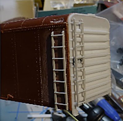
The other thing missing is the replacement levers for the Camel roller-lift mechanisms on the car doors. These were made from short lengths of scale 1 x 2-inch styrene strip, pre-painted, and installed with canopy glue, as shown below at right. The original Bowser door is at left. You can compare the model, below, with the prototype photos (see link in first paragraph, above).

The running board was cut apart, as mentioned above, and the center part installed first. The photo below shows the roof “indent,” nearest the camera,  which accepts the lateral running board. (You can click on the image to enlarge it if you wish.)

I then installed the lateral boards to fit, using canopy glue again. With all modeling and paint completed, I could turn to lettering, using the very nice decals provided for the project by National Scale Car. I chose to use the original all-white Seaboard emblem, since I have a bunch of Seaboard cars with the red “Heart of the South” emblems. 

Here is the model, fully lettered and awaiting weathering. You may note that I added a route card from the very nice decal set of such cards from Owl Mountain Models, their set 1220 (see: https://modelingthesp.blogspot.com/2023/12/route-cards-part-30-modeling.html ).

My usual weathering method, with acrylic washes, was applied to this model (for full description and examples, see the “Reference pages” link at the upper right of this post). I attempted to make the roof dirtier than the sides, as is often observed in the prototype, and then added a protective coat of clear flat (I prefer Tamiya’s flat, TS-80, nowadays). Then of course I added some chalk marks with Prismacolor pencils to complete the project.

This was an interesting Shake ’n’ Take project and I enjoyed doing it. I am also pleased to have one of these distinctive Seaboard cars in my fleet. Thanks to Steve Hile for his work on getting this together. Greg Martin would have been pleased.

Tony Thompson

Sunday, February 25, 2024

Investigating a model paint scheme

Awhile back I bought a model at a swap meet, an Athearn metal reefer nicely built up. This was obviously an event that took place a long time ago, because the car has Mantua couplers, not often seen in the hobby since the 1950s. It has an attractive paint scheme, so I decided to try and find out more about it, in particular, whether I could use it as you see it. This quest turned out to be an interesting example of how information can be pursued, which is why I’m reporting it.

I quickly learned that the paint scheme shown is the way the cars were delivered, with the green stripe at top and bottom of the yellow car sides, green side lettering, and aluminum roof. Side sill tabs and ends are black. The model has black ice hatch covers and running board, and at least the ice hatches should definitely be aluminum also. The new cars had placard boards and route card boards, and since these were also yellow originally, their outlines are printed on the Athearn sides.

I had a recollection that the roofs were later repainted, and I knew that there had been discussion among freight car people as to whether the ends originally were the same green as the side lettering. The consensus, back in the last century, was that the ends were indeed green. I can illustrate that point:

My late friend Richard Hendrickson maintained a file box of 3 x 5-inch cards, on which he wrote down information he could find about groups of cars on many railroads. I inherited this file, and here is his entry for these IC reefers. He does state that ends were green. Note that at the bottom he states that by 1948, roofs were black or dark green.

Consulting with the many freight car experts on the Steam Era Freight Cars list online, there were a variety of opinions. Soon, however, actual information began to appear. First, George Corral provided a General American builder photo of one of the cars, IC 50200, confirming the overall look of the car, and visibly riding on Type B trucks. General American built 300 of these cars in 1937, numbered IC 50000–50299.
Since my model doesn’t have trucks like this, I immediately thought of replacing them. But before I got underway with that idea, luckily I was directed by George to the Illinois Central’s diagram for these cars, as you see below. (You can click on the image to enlarge it if you wish.)
In the lower right corner, you will note the listing for trucks. Cars 50200–50299 did indeed have Type B trucks, as the builder photo shows, but the preceding 200 cars did not. My model, lettered as IC 50037, should have ASF double-truss trucks. The existing trucks are not an unacceptable version of that. By the way, this diagram reflects early 1950s revisions, by which time the cars had been retrofitted with Preco fans.

But what about the debate on end color? Opinions continued to differ, until Bill Kelly sent me copies he had made of the Illinois Central stenciling diagram on the internet. I really appreciate his generosity. Though not high resolution images, they do illustrate all the main points. I show an overall view below.

Here is Bill Kelly’s list of the paint colors from this drawing:

Roof  -  Aluminum
Moulding & Trimming - Black
Underframe - Black
Ends - Black 
Sides - Yellow P.P.G. Co. 29-16
Door - Yellow P.P.G. Co. 29-16
Side Sill - Green P.P.G. Co. 29-23
Side Sill Reinfororcement - Black

Stencilling:
Green on Yellow 
White on Green & Black

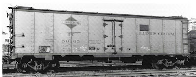
 This seems to settle the question of correct colors for these cars, as originally built. My model does have black ends, and I could paint all the roof parts aluminum. But then I would have a 1937 car, not really appropriate for my 1953 modeling year. For the appearance in later years, I would have to add fans and paint the roof and placard boards black. Not only that, but the IC emblem and reporting marks were moved to the right to clear the fans. Below is an in-service view, also from George Corral, showing this appearance, with the obviously retrofitted fan control.

I am not yet sure what I want to do. Perhaps correcting the car for 1937 and putting it in my display case would be a good move. I already have an IC reefer in my operating fleet and don’t really need more. (I might add fans to that car.) But I enjoyed learning about the history of these cars, which is why you’re reading this report.

Tony Thompson

Thursday, February 22, 2024

The steel express cars of PFE

A previous post on this blog showed both prototype photos, and model examples, of the wood-sheathed 50-foot express refrigerator cars in the Pacific Fruit Express fleet. Those cars, originally 300 in number and built in 1923, were supplemented in 1953 with 40-foot steel refrigerator cars, which are the subject of the present post. You can view the previous post at: https://modelingthesp.blogspot.com/2024/01/pfe-express-refrigerators.html .

Those 40-foot cars came about when PFE, responding in the summer of 1952 to a shortage of express cars on the part of the Railway Express Agency (operator of pooled express reefers from a number of owners, including PFE), drew 50 cars from the 4700-car class of steel cars, R-40-10, and equipped them for express passenger service. 

The cars chosen were among the R-40-10s that had already been upgraded with Preco electric fans and steel-grid running boards. The additional modifications included marker light brackets, upgraded brakes, steam and signal lines, and most visibly, high-speed trucks. They retained their Type E freight couplers rather than receiving tight-lock couplers.

There is more about these cars in Chapter 8 of the PFE book (Thompson, Church and Jones, Pacific Fruit Express, 2nd edition, Signature Press, 2000), for which I wrote all the parts about PFE cars. I also posted  previously, going into the history is some detail (that post is accessible at: https://modelingthesp.blogspot.com/2016/02/pfes-40-foot-express-reefers.html ).

The new batch of express reefers was numbered PFE 901–950. Below is a photo of the first car, PFE 901, at Los Angeles Shop, freshly painted but not yet weighed (PFE photo, CSRM).

Since the car bodies overall were unchanged, it is tempting merely to paint a Class R-40-10 model in Dark Olive Green paint on sides and ends (black roof), letter it in Dulux Gold, and have yourself a PFE steel express reefer. And that is basically what InterMountain Models did a few years ago. (And you could also add a fan control box and a steel-grid running board.) But the issue of trucks, at least, calls for more effort. I have briefly addressed that before; see my post at: https://modelingthesp.blogspot.com/2016/02/pfes-40-foot-express-reefers.html .

The prototype 50 cars, in process of being prepared for express service, received two sets of trucks that Union Pacific (co-owner of PFE) had been experimenting with, 25 sets of each type. These had been tested in UP’s high-speed stock trains from Salt Lake City to Los Angeles, but were superseded by roller-bearing trucks.

The first 25 cars, PFE 901–925, received a Chrysler FR-5 truck with hydraulic snubbers. The second 25, PFE 926–950, used the Symington-Gould Type XL trucks. Each is shown below, in photos taken from the PFE book. The Chrysler truck, with its prominent angled snubber outside, is at left; the Symington-Gould truck is at right.

As it happens, the appearance of the Symington-Gould truck is much like, though not identical to, the Cape Line T-13 truck, and I have used them to model a car from PFE 926–950. Shown below is the model of PFE 928, with the Cape Line trucks, being spotted for icing on my layout.

For the Chrysler truck, there is no commercial equivalent, but I’ve shown how I modeled this truck (see it at: http://modelingthesp.blogspot.com/2016/02/pfe-40-foot-express-cars-part-2-trucks.html ). The core idea was to add a resin casting for the snubber parts.

My set of these parts came from Ross Dando’s Twin Star Cars (you can visit them at: https://twinstarcars.com/WP/product-category/twin-star-cars-products//  ), though these parts are not currently on the website. If you wished to do the same truck modification, you would need to contact Twin Star directly to see if they can be ordered. Here is the truck with the Ross Dando casting attached.

The result was that I could model one of the first 25 cars in this PFE group. Here’s my model, starting with an InterMountain kit, correcting the trucks to resemble the Chrysler FR-5 and adding the etched metal running board (the fan control box is on the other side: there was only one per car).

I enjoy being able to operate these 40-foot steel express cars together with the conventional 50-foot wood-sheathed PFE express cars, reflecting the prototype fleet, whenever my seasonal produce shipping from layout packing houses calls for the use of express reefers.

Tony Thompson

Monday, February 19, 2024

Shake ’n’ Take Seaboard box car, Part 2

In the preceding post, I gave some background on the Shake ’n’ Take projects, invented by the late Greg Martin as features of the annual Cocoa Beach, Florida “Prototype Rails” meetings, which were long directed by the late Mike Brock.

I am describing the construction of a project to build a Seaboard Class AF-1 40-foot automobile car, modified from a Bowser body for a PRR X31 box car. This project was the work of Steve Hile. That previous post, showing replacement of ends, is here: https://modelingthesp.blogspot.com/2024/02/the-2022-shake-n-take-seaboard-box-car.html .

In that previous post, I had removed the Bowser ends and substituted new resin ends. Meanwhile, I was working on the underframe. An Accurail underframe was provided to the project. I added the Accurail brake parts and rigging, then used canopy glue to attach my usual car weights, 5/8-11 steel nuts, on the top side. (Those are just interim trucks.) I followed Steve Hile’s lead and didn’t detail the underframe beyond what you see.

Also needing work were the styrene doors supplied by Bowser. The doors have the type of Camel rolling-lift mechanisms correct for the Pennsylvania X31 box cars that Bowser models, but the Seaboard cars had a later style of this equipment (see the first post in this series, linked in the top paragraph above, for a prototype view). I used curved riffler files to clean up the Camel mechanism levers preparatory to adding new levers. In the photo below, the two center doors have been cleaned up, the two outer ones show the moldings as supplied. (You can click on the image to enlarge it.)

With the doors ready to install, I decided to add them at this point, as they are not fragile relative to later work. Then I could begin work on the body details. I began with the side and end ladders, partly because they need to be in place to position B-end brake details.  As I have begun to do in recent years, I used canopy glue to attach these. I have been impressed with the tenacity of this glue when set.

Below is one of Steve Hile’s photos at the stage I am at in the project. The side ladders are seven-rung and the end ladders are eight-rung; both are cut from the Des Plaines Hobbies ladders, and placed so that the rungs line up on side and end. The reason for this, if you think of a trainman on one or the other ladder, is obvious.

I continued with other details. I like to get the B end all put together before doing the A end or the sides, just getting all those parts done and out of the way. For attaching the grab irons, rather than drill holes to receive their locating pins, I simply cut off the pins and attached the parts with canopy glue, on both sides and ends. It worked fine.

I also decided to fill the holes in the roof, using Tamiya putty. When dry, this was sanded flat. A perfect fill wasn’t needed, I just didn’t want there to be voids underneath the running board. Here is the body at this point, almost ready for paint. Missing parts here are, of course, the running board, and the grab irons above the side ladder (those were bent from wire to fit the space). Trucks and couplers are temporarily installed.

The Kadee running board supplied for this project is an exquisite part, but it has no running board supports, nor does the Bowser body. The project box included Tichy running board supports, but they are intended for a peaked roof. Rather than fuss with sanding them down, I added the supports as styrene scale 2 x 4-inch strip, attached to the bottom of the running board. 

It seemed logical to me to attach them to the running board before putting the running board on the body, rather than try to align them perfectly on the roof prior to running board installation. The underside of the running board can then be painted along with the body. With Steve Hile’s comment that the Seaboard color was “on the brown side of boxcar red,” I  painted the running board with Tamiya “Red Brown,” color TS-1. Its underside is shown below.

One further note: though the running board is a good length for the Bowser body, the lateral boards are not located at the right point to fit the body’s roof. I will slice the two lateral boards off, install the main board, and then come back and glue on the lateral boards later, all with canopy glue.

With the running board about ready to install, and the body ready for paint and lettering, I’ll close this post, and continue in a future post.

Tony Thompson

Friday, February 16, 2024

Waybills, Part 113: freight train procedures

Recently on several internet groups. attention has been called to an excellent Santa Fe color film called “Assembling a Freight Train.” It’s just 11 minutes long, and if you like, you can view it at this link: https://www.youtube.com/watch?v=tRXMvR7DBkc . It has enjoyable close-ups of numerous freight cars (evidently dating from about 1955), but what I liked the most is the depiction of the work of the clerks and carmen, particularly the parts having to do with route cards and waybills.

I will show a few screen grabs from the film, intended to clarify what each one shows and what they can tell us about prototype operating procedures. The freight car paperwork depiction begins with what Santa Fe called an “industry clerk,” who visited shippers to collect the Bills of Lading that they had filled out, and likewise (to me, this is the interesting part) to attach appropriate route cards to the cars (shown below on a refrigerator car).

Though this at first glance seems like an urban procedure, where shippers are not distant from the yard, it could certainly be the practice in any small town too. I am not aware that other railroads did it this way, nor that Santa Fe did it this way everywhere, but notice it means that cars arriving in the yard as outbound loads would already by marked for destination.

A further interesting detail is that the same industry clerk shown above, is also shown in a very brief clip attaching a route card to a tank car, attaching it to the edge of the wood running board. I know this was common, so it’s interesting to see it shown here.

But evidently not all cars were carded by an industry clerk before leaving the shipper, because the film also shows a clerk putting route cards onto cars in the yard.

There are a couple of close-ups of Santa Fe route cards in the film, such as the one below; this format is familiar from other examples (see this post: https://modelingthesp.blogspot.com/2016/07/route-cards-part-11-examples.html ). Here an actual tack is being used to attach the card.

Then the film shows a yard clerk using the Bills of Lading as the information so he can type the waybills. An interesting part of this view is that this is a typical “billing typewriter,” with a very wide platen. These typewriters were usually only capable of upper-case or capital letters, which is why most waybills before the 1960s had no lower-case letters typed on them.

As the train is being made up for departure, now the yard clerk takes the fresh waybills and a wheel report form out to the train crew. He is shown below walking across the yard. The larger form on the bottom of his stack is the wheel report; on top are the waybills.

For the camera’s benefit, the clerk riffles the stack of waybills, which is quite interesting for two reasons. First, you can see that all the waybills are already folded in half the long way, typical practice throughout the country. And among those bills are some Empty Car forms, manila in color and the same width as the folded waybills.

All this conforms well to what I had already understood about the process of waybilling and use of route cards. But I quite enjoyed seeing this process illustrated in a film made by the railroad about its own work. And as I mentioned, a nice additional benefit is that there are lots of good views of mid-1950s freight cars. I’ve watched it all the way through several times (only 11 minutes, after all), and still enjoy it.

Tony Thompson

Tuesday, February 13, 2024

Another Maintenance of Way model

I find most Maintenance of Way (MOW) cars interesting, and they offer some distinctive modeling opportunities and challenges. The Southern Pacific was certainly no exception to this. One way I incorporate them into my layout is that I have provided what SP called an “outfit track,” a spur set aside for MOW use in certain locations. This is a natural place both to place static displays of MOW models, and also to switch, in that equipment may come and go from such a track. 

Recently I was reviewing some of the MOW photos I received from Arnold Menke. and below is an image taken by L..L. Bonney at West Oakland on November 22, 1938, of a boarding bunk car, SPMW 4622. It’s evidently based on an old box car, with light-duty trucks. Note that window screens are outside of the sliding windows, and that there is no end door (though such doors were common on boarding box cars).

Why did I focus on this image? Because it suddenly registered with me that I have a model of this exact car, built I believe by Al Massi (or from his collection), a scratch-built car which is hand-lettered in white ink.

What’s the background to this car? One naturally turns (if so equipped) to Ken Harrison’s magnificent book, Southern Pacific Maintenance of Way Equipment (SPH&TS, 2022), which I reviewed when it came out (see: https://modelingthesp.blogspot.com/2023/02/ken-harrisons-marvelous-addition-to-sp.html ). The book pages are amazing enough, but still more amazing is the enormous collection of roster data, supplied on a disk inside the back cover of the book. 

This information reveals that SPMW 4622 was converted from a 30-ton box car owned by El Paso & Southwestern, one of a group of American Car & Foundry-built EP&SW box cars from 1902. The EP&SW had already converted the car to MOW use, numbered 1163, by the time of the SP takeover in late 1924 (it is listed in EP&SW entries in Official Railway Equipment Registers prior to that date), though the official date of SP’s MOW conversion at El Paso was in October of 1925. Of course. the El Paso shops may well have modified the car to suit SP needs at that time.

The car design seen in SPMW 4622, with “over-and-under” windows, was widely used by SP for boarding bunk cars. Here is another example, from the John Signor collection (date and location unknown), a Class B-50-6 box car converted to MOW in 1942. It was the third SPMW car to carry the number 80. Again, there is no end door; but note the shadow of a tank car on the end, probably a domestic water car for the outfit. Stoves in this era on the SP burned coal.

Another interesting example, with slightly different window pattern, is SPMW 1728. It’s another L.L. Bonney photo, taken at Truckee in 1960 (Arnold Menke collection). It was originally Class B-50-2 box car 86529, and was converted to MW in 1939. The tall chimney is noteworthy.

I have long thought about making up styrene sides for such cars, not too difficult a job but fiddly work with all the window framing to place. But the cars I already have may well meet my MOW needs. The scratchbuilding possibility is going to stay on my “long-range” project list.

Tony Thompson

Saturday, February 10, 2024

The 2022 Shake ’n’ Take Seaboard box car

The late Greg Martin originated the idea of what he named “Shake ’n’ Take” model projects, meaning relatively straightforward kitbashing or kit modifying projects, which were presented at the Cocoa Beach, Florida “Prototype Rails” meetings. Richard Hendrickson and a number of others have pitched in over the years to help choose prototypes and build the models for these projects. 

You had to sign up for the project and attend a clinic about it at Cocoa Beach. With the cooperation of a number of manufacturers and other producers of model railroad parts, participants at the clinic were given a car body and associated parts, ranging from underframes and major parts, to very minor parts like side-sill tabs or brake steps, and often custom decals.

The first of these projects was presented at the 2006 Prototype Rails meeting, and it was a rebuilt Kansas City Southern box car. I built that project and reported on it in blog posts (see the conclusion of the series at: https://modelingthesp.blogspot.com/2012/07/shake-n-take-kcs-rebuilt-box-car.html ). For those interested, I show below a list of all the projects, taken from a PDF by Ben Hom on the groups.io site for these projects: https://groups.io/g/shake-n-take/files ).

I have signed up for most of these projects, though I skipped a few. They involved cars that were too late for me (the PRR Class X45 in 2008), too early for me (the 2024 project), or cars I didn’t need because I already had them (the 2009, 2012, 2014, and 2020 projects. But I have built most of the rest. 

Among those that I have reported on were the Kahn’s reefer (see: https://modelingthesp.blogspot.com/2011/12/shake-n-take-modeling-project-kahns.html ), the DT&I gondola, one that I really enjoyed doing (described at: https://modelingthesp.blogspot.com/2012/01/shake-n-take-modeling-project-dt.html ), and more recently, the Hormel reefer (conclusion at: https://modelingthesp.blogspot.com/2020/07/my-greg-martin-car-part-2.html ).

Greg’s original idea was that these would be a “weekend project,” and for most of us, the projects have grown well beyond that! But they have been interesting cars for the most part, and some of the kit modification ideas quite ingenious. We have been having quite a bit of rain where I live, so it seemed like a good time to look at one of these projects in my stash: the 2022 Seaboard box car. Here’s a builder view (Pullman-Standard photo, Illinois Digital Library):

These cars were built by Pullman-Standard at their Bessemer, Alabama plant in 1940, 700 cars numbered 11000–11699. Their round roof is reminiscent of the Pennsylvania “wagon-top” cars of the X31 subclasses, built in 1936. But the Seaboard cars were distinctive in having a proprietary end stamping that was different from the PRR cars (builder photo below, same credit). Accordingly, this Shake ’n’ Take project is to use the Bowser round-roof body, and to replace ends and some other details.

Before describing the modeling, I should credit the various donors of parts for this project. Bowser contributed the car bodies and doors; Accurail, the underframe, brake parts, and trucks; Southbound Model Works, the resin replacement ends; Kadee, running boards, brake wheel and step, grab irons; Des Plaines Hobbies, ladders; National Scale Car, resin side sill tabs, tack boards, and decals. The generosity of them all is appreciated. Steve Hile designed the project, gave the Cocoa Beach clinic on it, and wrote the directions.

To begin the model work, I removed the molded-on side ladders and grab irons. They are of very low relief, and are removed so that better parts can be substituted. For removing details like these, I take a brand-new #17 X-Acto blade to carefully slice away whatever isn’t wanted. Finally, the Bowser body has double rivet rows at some side panel boundaries, so the extra rows were removed.

The more substantial modification began with removing the Bowser ends, conventional Dreadnaught configuration, which are to be replaced. I used a razor saw to slice inside the side walls, along both sides of the end, then a knife groove was made across the top of the end, so it could be snapped off. Here’s a view before sanding the end completely flat.

I then followed the project directions and added an end bulkhead of 0.040-inch thickness styrene. I reinforced the inside corners with 1/8 x 1/4-inch styrene strip. This stabilizes the body as well as providing a gluing surface for the replacement ends.

With these bulkheads in place, and with the new resin ends carefully cleaned up to fit, I glued the new ends in place with canopy glue. Here is the car at this point, just needing addition of all the smaller details before painting.

I will continue with descriptions of the work on this interesting project in a future post.

Tony Thompson

Wednesday, February 7, 2024

A model railroading weekend

I’m reporting today on something that I haven’t often reported before, but it occurs to me that it may be informative for some readers to revisit the topic (there is an earlier report at: https://modelingthesp.blogspot.com/2018/01/the-bay-area-layout-design-and.html ). It’s a meeting that’s been held in the San Francisco Bay Area for about 25 years, chaired during practically the whole time by our own Seth Neumann. The weekend chosen has always been the ”football-free” weekend before the Super Bowl, for what I assume are obvious reasons. To see the current announcement, you can visit: http://bayldops.com/ .

This meeting began, all those years ago, with 8 or so people meeting in a living room, and had grown past 100 attendees before the pandemic. We had about 80 this last weekend (a mix of in-person and virtual attendees). It encompasses both layout design and operation through the respective NMRA Special Interest Groups or SIGs, the Layout Design SIG and the Operations SIG. In recent years, the site has been rotated among the South Bay, East Bay, and North Bay in the immediate Bay Area, and Sacramento.

This is something that could be done almost anywhere, as a means of getting people together with common interests (such as, but not limited to, the two SIGs mentioned above). I can recommend discussions of layout design issues, and even a “design challenge” — ours was to design a small layout to model the Northwestern Pacific terminal and ferry dock at Tiburon — something the Bay Area meeting has long included. This is invariably an intriguing component of the day, as various respondents show their layout ideas, and I’d recommend it. 

Anyone planning such a meeting might also consider including discussions of operation procedures, whether in the form of talks, panel discussions, or audience participation. Also, attendees always enjoy evening or next-day layout open houses and open operating sessions. We have long had these, and they seem like obvious possibilities for other meets.

This year, our meeting schedule began with Friday layout open houses and a dinner, then quite a nice Saturday meeting of our usual kind, a bunch of talks (I gave one of them), the Tiburon design challenge, which brought forth some quite interesting responses, and a switching puzzle. 

We also had our usual “layout design consulting,” where experienced layout designers privately evaluate your layout ideas or design, one on one, and give feedback. This was followed on Sunday by operating sessions for the Saturday attendees.

I was at Paul Weiss’s outstanding Central Vermont layout on Sunday, to act as yardmaster at the principal yard, East New London. It was a really rainy day, somewhat unevenly with heavy showers alternating with light ones, but still a very gray and wet day. Here’s a view from the layout door with rain pelting down (and yes, that’s a crossing gate in the distance: the former NWP line, now SMART commute trains):

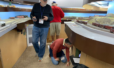
But inside, of course, we were dry and happy (doubtless aided by the availability of copious coffee and donuts). My crew at East New London was Jim Radkey and David Gibbons, both experienced people who got all the yard switching done in a quite timely manner. Adjoining our yard was one of the windows to an operator’s desk at the lower level, sometimes resulting in amusing scenes like this: Robert Bowdidge, conductor on the Montville job, kneeling down to communicate with the operator; at left is Phil Edholm, Superintendent of our local NMRA division, and behind him, Jim Radkey.

The layout is being built and developed by an impressive and talented crew. I always enjoy each visit because progress is always evident. The crown jewel of the new work is the superb model, built by Doug Nelson, of the Union Station at Palmer, Massachusetts (the prototype still stands), an H.H. Richardson stone structure. In the view below, the double track in front of the depot is the Boston & Albany main line, with the CV crossing at right.

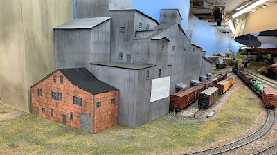
Another very impressive new structure on the layout is the Yantic Grain & Produce mill and elevator, shown below. This faithfully reproduces the remarkably complex prototype structure’s roofline, and the addition at left, with a quite good representation of New England’s ubiquitous “insulbrick” sheathing, the work of Jim Providenza. A great model, and now an interesting industry to switch!

It was, as always, a fun weekend, with lots of friends and acquaintances to meet and reconnect with, nice information in the Saturday session, and (for me anyway) a terrific operating session on Sunday; I’m sure others enjoyed their Sunday layout sessions too. 

But as I stated at the outset of this post, my point in describing all this is that I think this kind of get-together could be reproduced in many places, and local modelers would have the chance to enjoy them as much as I do ours. If you see an announcement for such a meeting in your area, I’d recommend you give it a try. And if there is no such meeting locally, why not organize one? I always enjoy them, and I’ll bet you would too.

Tony Thompson

Sunday, February 4, 2024

Modeling an SP Class O-50-9 tank car, Conclusion

This series of posts is about modeling the last class of tank cars that Southern Pacific purchased that had circumferential rivets joining its tank sections. Designated Class O-50-9 (for Oil car, 50 tons capacity, ninth class), the cars were built by General American in 1924 and were numbered 47880–48079. (All subsequent SP tank cars were numbered in the 58,000 series prior to the 1956 renumbering.) Below is a builder photo (General American photo for SP, author’s collection).

Prominent in this photo are the original T-section trucks and K brakes.  Both were replaced after World War II, as documented in the SP Car Ledger records (described previously, at: https://modelingthesp.blogspot.com/2024/01/modeling-sp-class-o-50-9-tank-car-part-4.html ) on nearly all cars. Accordingly, my model has those changes also.

The model, degree of completion of which was shown in the post just cited, now needed to be painted. I used Tamiya “Rubber Black,” TS-82, a not-quite-dead black color, and painted both tank and underframe this color. Here is the model at this point, with Kadee #158 whisker couplers installed, and Athearn trucks with Reboxx “scale-width” wheelsets. The safety valves are toward the B end of the car, as they should be.

The paint scheme shown in the prototype photo above was replaced in 1946 by a scheme in which the road name was spelled out. Below is part of an SP lettering diagram (you can click on the image to enlarge it if you wish). The drawing you see here had been revised in 1952 to remove stripes above and below the name and car number, but since SP tank cars were rarely repainted, I decided to retain the stripes as indicating a pre-1952 paint scheme. (You can click on this image to enlarge it, if you wish.)

I used Tichy decal set 10053 for lettering. I did the original art work for this set, as Tichy has been kind enough to note on the decal sheet itself. The sheet does contain everything needed to letter one of these cars, following the prototype diagram, including suitable built dates, gallonage capacities, and class numbers.

Next came weathering. As I nearly always do, I used my acrylic-wash method (see links to “Reference pages” in the upper right corner of this post) to weather this car. This car also has route cards and a few chalk marks. Only remaining task is to add placards; but that’s really a separate topic, about which I’ve provided background before (see, for example: https://modelingthesp.blogspot.com/2012/03/tank-car-placards-modeling.html ).

This has been a fun project, despite having been set aside for awhile. It adds to the completeness of my fleet of SP tank cars of the 1950s. And this one is certainly going right into service on the layout!

Tony Thompson

Thursday, February 1, 2024

Trackwork wars, Part 9

From time to time, I document some of the maintenance and upgrade work done on my layout. The most elusive solutions and most persistent problems seem to be trackwork and electrical ones, thus the names of a series of posts about each, under the “wars” title. The “electrical” series is the longer, but as the present post demonstrates, I have my share of trackwork problems too. 

The previous post in this series,though not a logical predecessor as it was in an entirely different part of the layout, did focus on track leveling issues (see that post at: https://modelingthesp.blogspot.com/2023/12/trackwork-wars-part-8.html ). That was very much an issue in the area to be discussed in the present post, which is shown below.

This is the area where the layout transitions from the town of Ballard, to the left of the creek, to Santa Rosalia, at the right of the creek. It has been troublesome for some locomotives in several previous operating sessions, but recently has become worse. 

The building with the gray roof, against the backdrop, is the site for the MP1 switch machines powering the adjacent switches. (For a discussion of the MP1 machine, see: https://modelingthesp.blogspot.com/2019/02/powering-turnouts.html ). With that building removed, the MP1’s are visible (below). I’ve been pleased with these linear-motion switch machines, following their installation (see: https://modelingthesp.blogspot.com/2023/03/powering-few-more-switches-part-2.html ). It was essential to use surface-mounted switch machines in this area because there is trackage right under it.

Note in the above photo the small level on the track at left. I quickly discovered considerable variations in track level over short distances, an excellent arrangement to cause derailments. Even this simple tool can easily reveal the level differences that are causing trouble, as you see below. The area depicted in both photos is a close-up of the area shown above, one photo for each switch.

This sharp difference in level over a short distance has to be corrected. I used white styrene (HO scale 1 x 10-inch strip) to cut shims, and try them out under the track to get closer to cross-level throughout. Below is a first cut at these corrections. They are not final, but closer to what is needed.

The next step was to try and use the transparent “test car” to check consistency in the track leveling. One attempt is shown below. But this is not a very effective test, because the truck mounting is not very stable against tilting. One can carefully level the car, and try to gently move it over the track to be tested; but even the slightest of bumps will change the tilt of the car. Something better was needed.

My next test was to bring one of my steam locomotives to the area, and slowly and rapidly back through and then go forward through, the affected area. After all, this is the real goal of the track project, to avoid derailments. This is shown below. Note that the trackage being tested is all unballasted, which won’t change until the track problems are at least close to “fixed.”

Much of the previous problem, and at the usual derailment location, was remedied. But one position of the switch to the right in the above photo still gave some derailments. So further work is needed beyond the leveling that was described above. I will return to this problem.

The work so far seemed successful, though more is needed, and more thorough testing. Of course, the real test, as any layout owner knows, is an operating session with visitors, ideally ones you want to  impress; but that will have to wait. Right now, things are certainly improved, though I need to continue to experiment, modify, and of course, test and test . . .

Tony Thompson