Friday, March 31, 2023

Modeling another SP diesel fuel car

My operating sessions normally are primarily steam-powered, with a few diesels, reflecting the reality on Southern Pacific’s Coast Division in 1953. The most visible diesel is a switcher that is normally used in the yard work at Shumala, in part because it is shorter in length than an 0-6-0, and in some cases that makes the work easier.

But until recently there was no storage tank for diesel fuel in the Shumala engine terminal, so no need to spot tank cars of that fuel anywhere. That changed when I finally added diesel fuel storage a few months ago (for a description and photo, see this post: https://modelingthesp.blogspot.com/2022/12/adding-storage-tanks.html ). That post also shows one of SP’s tank cars with the distinctive aluminum-painted end band, the diesel fuel scheme used after 1951.

But SP originally (in the late 1930s, to service the diesel locomotives of the City of San Francisco, SP’s only diesels at the time) had painted such cars with aluminum tanks and black lettering, and continued to use that scheme into the 1950s. I wanted to model one.

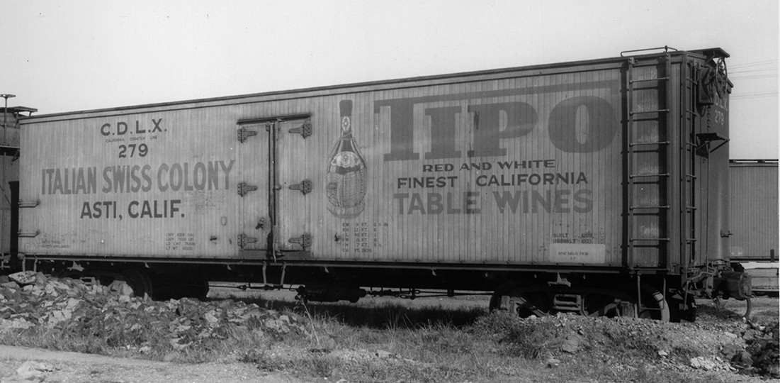
Below is a photo of the left side of one such car, SP 58409 (at left of the photo is the end of an aluminum-stripe car, as mentioned above). Built in the summer of 1928, SP 58409, Class O-50-12, received the all-aluminum scheme in 1948 when it was assigned to diesel fuel service. The photo was taken at Los Angeles on January 22, 1955 (Chet McCoid photo, Bob’s Photo collection, used with permission). The spillage, incidentally, is another modeling goal!

[For more on these tank cars and their paint schemes, you may consult Chapter 14 of my book, Southern Pacific Freight Cars, Volume 5: Hoppers, Covered Hoppers, and Tank Cars (Signature Press, 2008).]

To model a car like this, I used my normal modification to the Athearn “42-foot” tank car. I posted a full description of this process some time ago (see it at: https://modelingthesp.blogspot.com/2011/05/modeling-sp-tank-cars.html ). Accordingly, I won’t go into those preparatory steps, except to show the core of the work on the tank body, as described in the post just cited.

Below is an illustrative photo of an Athearn body. The dome height has been corrected by adding the top of another dome, the safety valves have been re-located to their correct position, the dome walk on the near side has been removed, and I have sanded off the extraneous rivet rows near the dome on the original body. The safety valves were always toward the B end of the car, thus the removed walk was on the right side.

The present project is intended to correct mistakes in a project that’s been stalled for several years, because of an error I made. Below, I show the modeling at the point that the dome height has been corrected but the dome walk was removed on the wrong side (typical SP practice to have a walk only on one side, the left). You can see I have already done some lettering. Note also the new wire grab irons at tank ends. The next step on the body is to correct the wrong-side walk removal, and to make a new handrail.

One option would be to remove the walk on the far side of the model shown above, and build a new one on the near side. But there is a simpler solution: remove the safety valves from their location shown above, and re-install them on the other side of the manway cover. Since those valves are always toward the B end, moving them immediately makes the walk-less side into the right side of the car.

Once that correction is made, next comes work on the frame. To the kit underframe, I usually add some brake piping and rigging with wire, because it is so visible on tank cars. Below is an illustration of a minimal amount of this modification.

Before going any further, I should mention that SP’s silver diesel fuel tank cars had black bottom sheets. Commercial models have sometimes missed this point, but prototype photos are quite clear (for example, see the one at the top of the present post). 

For another example, the view below was taken at Tucumcari, New Mexico on December 17, 1947, and though the photographer doubtless was far more interested in Class AC-9 no. 3807, it’s also a fine view of the left side of diesel fuel tank car SP 58691, Class O-50-13 (Al Phelps photo).

Correcting the dome top and forming a handrail are the first tasks. Then, regarding finishing, obviously I need to add a black bottom sheet to my model, along with touching up the body paint and completing lettering. I will return to this modeling project in a future post.

Tony Thompson

Tuesday, March 28, 2023

The wine tank cars of AAR Class XT

 The tank cars that were classified by AAR as “XT” were described as “A house car with or without doors, with or without insulation, either metal lined or enclosing one or more tanks.” This means that on the outside, such a car looks nothing like a tank car. Since I have a few such cars in my freight car fleet, and do include them in operating sessions, they sometimes generate questions.

The first question is usually something like, “Why didn’t they just use tank cars?” I don’t know for sure, but suspect it was a matter of cost. The model cars I have all represent cars that the new owner purchased used from Pacific Fruit Express, old cars that were likely sold well below a new-car price. The car is already insulated, so all it needs for tank car use is the tanks.

There were 41 of these cars, purchased by California Dispatch Line, a major lessor of equipment for wine transport. There is much more about them in the PFE book (Pacific Fruit Express, 2nd edition, Signature Press, 2000), located in Chapter 4.

We know from PFE records that the roofs were removed, in one piece, tanks put inside, and the roof put back on. In most cases, ice bunkers were removed inside, to make more space, but in many cases, the ice hatches were left where they were, so that the original roof structure could be retained. At least some cars had hatches removed and the opening blanked off. Either way, the car is no longer a refrigerator, it’s an insulated house car. Here’s a view of a model roof with blanked hatch openings.

Some years ago, Red Caboose used their PFE wood reefer model in HO scale, and applied a number of wine lessee schemes to them, at least three of which have prototype backing. For example, here is a car obviously leased to Italian Swiss Colony in Asti, California (photo at Oakland, February 11, 1939, by Wilbur C. Whittaker). 

This scheme is one that was copied by Red Caboose, and in this case the colors are known, from the Italian Swiss advertising of the era. Here is one of these models, being switched across Nipomo Street in my layout town of Ballard by Consolidation 2752:

Another Red Caboose model had its logo design and color based on a CDLX car found at a logging camp, lettered for Roma Wine Company. Below, you see it spotted at the winery on my layout. (You can click on the image to enlarge it if you wish.)

Most of these CDLX cars contained six glass-lined tanks of about 1000 gallons each. (The familiar six-compartment wine tank cars also had about 1000 gallons per compartment.) Some other XT cars contained just two tanks, of 3000 gallons each. Though I don’t have an interior photo of the wine cars, the view below (a General American photo) shows a 3000-gallon tank in a milk car. This tank has its own insulation, in addition to that of the car itself.

So some of the wine that is shipped out of my two winery facilities on the layout do move in these distinctive tank cars: AAR Class XT, in former PFE reefers owned by CDLX, and leased to wine growers, processors or marketers.

Tony Thompson

Saturday, March 25, 2023

Modeling in O scale, Part 3

I’ve exposed my clandestine interest in O scale, especially freight cars, in a couple of previous posts. When I lived in Pittsburgh, PA I could run this equipment on my late friend Larry Kline’s layout, but now I am going to be reduced to a display case. The preceding post on this topic is here: https://modelingthesp.blogspot.com/2023/02/modeling-in-o-scale-part-2.html

In the first previous post, I showed two of my O scale models, an Athearn metal box car (originally owned by Paul Shimada) and a styrene PFE steel reefer from InterMountain. Another Athearn metal model that I like is a 50-foot automobile car (defined by the AAR as a box car with double doors, regardless of the cargo it carried) This one is decorated for the St. Louis Southwestern, or Cotton Belt, in the famous “Blue Streak” paint scheme. Cars like this often operated in automobile or auto parts service in the train with the same name, the “Blue Streak Merchandise,” from St. Louis to California.

Next I will mention a two-compartment American Car & Foundry tank car I have, a W.A. Drake model, that was factory painted and lettered as SHPX 83. This car was included in the 1956 tank car tariff, though with slightly different capacities of the two compartments, compared to what is lettered on the model. Note the single ladder, aligned with one of the domes, at the right end of the dome walkway. It’s the same on both sides.

This model came without trucks or couplers, so I had to add those. So far this model hasn’t been weathered, though cars like this got pretty dirty in service. I may get around to weathering it one of these days.

Another model I really enjoy owning is another contribution from my good friend Larry Kline (he built it for me). It represents a PFE rebuild of Class R-40-4, and like all those rebuilds, numbered into the 71,000 series. There was also a much larger group of Class R-40-4 cars built new by PFE, in a different number series. There were 510 cars in this rebuilt class, numbered variously from  71253 to 71953, with additional rebuilt Class R-40-2 cars mixed in that number series. It is modeled with the 1942 paint scheme. 

Finally, I do have a locomotive (essential in the days I could run on Larry’s O-scale layout!). I managed to find a Pacific Fast Mail SP Class C-9 Consolidation, SP 2579, for sale, painted and set up for sound. 

Southern Pacific and subsidiaries bought 225 engines in this class, so the model represents one of the largest SP steam classes, and many C-9s lasted to the end of steam. Here is a shot of my model, obviously unweathered  but a delight to operate. And yes, the red trim is prototypical.

With the equipment I’ve shown so far, I can mount a pretty good train, and I have really enjoyed the times I was able to operate these cars and locomotive together. I have already started installing my O-scale display case (saved from Pittsburgh), so that some of these attractive models can be seen in the layout room.

Tony Thompson

Wednesday, March 22, 2023

BayRails IX, 2023

 This last week, the ninth edition of the BayRails operating weekend was held. As has been true in recent years, my layout was on the schedule, and I hosted two sessions, on March 17 and 19. The usual four-person crews visited to run the layout.

On the first day, the 17th, my crew comprised Tom Callan, Bill Jolitz, Mike Jordan, and Steve Schiffman. I was especially happy to host Mike, as I had really enjoyed operating on his layout in Minneapolis and exchanging information and ideas about reefer operations (PFE in particular). Since Bill has very similar interests as Mike and me, the two of them really had great fun. Here they are, switching at Shumala, with Mike acting as conductor at left.

And because Mike and I have enjoyed getting to know one another, and operating on each other’s layouts, Bill Jolitz took a photo of us together. I see at photo right that the crew was about to spot a gondola of sand at the Shumala sand house.

The other crew was also photographed when it was their turn at Shumala, with Tom at left. At this point, Tom was clearly doing the engineer’s job, since he’s holding the throttle.

On Saturday the 18th, I was acting as yardmaster at Paul Weiss’s Central Vermont, a job which I’ve documented <grin> in a recent post (see it at: https://modelingthesp.blogspot.com/2023/03/layout-operating-can-be-demanding.html ). Then on Sunday, my layout was active again. This time, the crew was Dave Clune, Al Daumann, Eric Dervinis, and Jeroen Gerritsen. Below, Eric (at left) and Al Daumann, clearly the conductor, are working at Shumala.

The other crew, Dave and Jeroen, were at Ballard, with Dave as engineer. They appear to be quite puzzled by something, hopefully not my paperwork.

This was a good weekend, as far as I could tell, and all the operators I spoke with, at my layout or at Pal’s, seemed to really enjoy it. So after missing our chance to host a BayRails in 2021 during the pandemic, it is nice to have this event back.

Tony Thompson

Sunday, March 19, 2023

Layout operating can be demanding

 There can be many meanings here of “demanding,” but I refer in the present context to physically demanding. This is of course not what one usually associates with operation, but I will show a vivid example.

It happens to be drawn from a session at Paul Weiss’s excellent Central Vermont layout here in the Bay Area. I have taken on the assignment of Yardmaster at the principal yard, East New London, several times. This job was envisioned as operating out of an office below the layout, where desk space and telephones were provided. 

The communication with the yard crew was intended to be through a window at floor level in the layout, but for the yardmaster, at desk level in the office.

This is really a clever idea in one sense, to find office space outside of the layout operating area. In the photo above, you see reflections in the upper window of people standing in the aisle. The gray desk surface is evident.

The working space for the yard crew is generous, a fairly wide aisle, with that window at one corner of the long dimension of the yard. Here is a distant view, with yard switchman Paul Deis at work. The yard is the lower layout level in this view, with the office window below.

Well, the phone by which the dispatcher can call the yard for information is inside the window, to the right as you face it in the photos above. But such a phone call isn’t easy to take if, like me, you prefer to supervise your yardmen in person, up at layout level. In one session, I took such a call by lying on the floor, with head through the window, as you see here.

This position looks dramatic (though actually not too uncomfortable, provided the call is short). But a  closer view may not look quite so relaxed.

From the office side of the window, it looks distinctly less comfortable, and that’s probably an accurate view. These three photos of me are by Paul Weiss (he was fascinated by the use to which his facilities were being put).

Paul and I discussed this problem, and realized that there are two possible solutions. One would be to add a phone outside the office window, on the layout side, up at waist level. That would make it quite easy for the yardmaster to take calls. The other solution is for me to train the dispatcher not to call the yard. That’s almost certainly faster and definitely less construction. We’ll have to see where it goes.

Tony Thompson

Thursday, March 16, 2023

Powering a few more switches, Part 2

In the preceding post, I described a project I am undertaking to power some layout track switches that are awkward to operated manually, at the boundary between my layout towns of Ballard and Santa Rosalia (here is a link to that post: https://modelingthesp.blogspot.com/2023/03/powering-few-more-switches.html ). 

 An important part of this project is to design and build a new control panel, where the new electrical switches for these switch machines will be located. 

My first effort to use an MP1 linear-motion switch machine (as I had described in an earlier post: https://modelingthesp.blogspot.com/2019/02/powering-turnouts.html ) gave rise to this obviously temporary and rather clunky panel, showing the selection of either Track 7 or the main line (it’s just a scrap piece of Upson board):

Now, of course, I was going to re-locate the switch you see above, and add to it at least two more switches. I realized I could also perhaps power the switch between main and siding in the town of Ballard, which would be good to plan for. So I grabbed a piece of scrap card stock, eyeballed the approximate size that would fit the space where the clunky panel (above) was located, and sketched what might work.

Here I tried to reproduce the curvature of the mainline track in this area, just using a kitchen mixing bowl upside down to make a curve of the right size. I drew rough circles where each electrical switch could be located, four in all. Then I experimented with labels, making up a few to see how they would look, and how they should be arranged. I used the Hamilton type face, in 16-point size, which is what you see above.

Based on my experience, I know that the simplest way to do a track diagram is to start with the base color (in my case, I chose yellow) and use masking tape to make the track. Then over-paint with a final panel color (black). So the first step was to reproduce (approximately) the sketch above. Here is my piece of yellow-enameled Masonite, with tape applied. Note that I would now have to re-make the labels shown above, to be yellow letters on black.

 I then oversprayed this panel with Tamiya Matte Black (TS-6) and let it get mostly dry, then stripped off the tape. Tape will come off more cleanly at this point than later, in my experience. Here is the result:

Next, I re-made the labels you saw above, to have yellow lettering on black (easy in Photoshop). These labels were printed out, cut to size, and applied with canopy glue. Then holes were drilled for the four SPST switches (though only three would be installed at this time, as shown below). Also visible are the two wood screws attaching the panel to a support behind.

Incidentally, the empty hole at left is intended for the control of the track switch I showed in the previous post, the one that is operated by a Caboose Industries ground throw far from the switch itself (the last photo in this post: https://modelingthesp.blogspot.com/2023/03/powering-few-more-switches.html ). It isn’t powered yet.

With the panel complete and wired, I could go ahead with mechanical installation of the MP1 switch machines. I will show that work in a future post.

Tony Thompson

Monday, March 13, 2023

Waybills, Part 107: tank cars

I realized in some recent discussions that I had not ever really been specific about some tank car issues, both about waybills and about cargoes. Because these touch on other issues of tank car handling and use, I will summarize those briefly also.

To begin, non-pressure tank cars (ICC types 103 and 104, the overwhelming majority of tank cars in the transition era) were loaded through the dome manway, the dome-top opening. Here is an excellent view of that process. (The photo was taken by John Vachon in November 1942, at the Phillips refinery in Borger, Texas; the image is from the Library of Congress, image no. LC-USW3-011638. I’ve written about Vachon in an earlier post: https://modelingthesp.blogspot.com/2016/01/vachon-tank-car-photos.html .) This happens to be a screw-top manway cover.

Such cars had bottom outlet valves (controlled by a long shaft up into the expansion dome, and operated from there). Many photos show this kind of unloading; this one is a Standard Oil photo at Bayway, New Jersey (undated). The nearest tank car, with CYCX reporting marks, belonged to the Conley Tank Car Company. Note also the wheel tread width . . .

On the end of the CYCX tank car, the gallonage is prominently displayed. In the era of riveted tank cars, manufacturing did not produce identical tanks, and each car, when completed, had to be measured and its exact gallonage determined. What did this refer to? It was called the “shell-full” capacity. This was the amount present when the liquid just filled the horizontal part of the tank. It could be easily seen through the manway.

This gallon-capacity is the reason tank cars were not often reweighed; their light weight was not used in calculating cargo weight, as it was in practically all other freight cars. Instead, the convenient loading determination of “shell full” equalled the gallonage on the tank’s end. This gallonage was then the basis for tariff charges.

But the tariff was not actually in gallons, in that if you look in a tariff, the tariff quantities are on the basis of a stated weight per gallon. Obviously you just multiply that factor times the gallons to get weight. As an example, xylene and lubricating oil were both listed as 6.6 pounds per gallon.

This entry is a tariff revision, one of the innumerable and frequent changes to rules in the days of ICC regulation of railroads. It is from this book, tellingly titled “Supplement 72” of Freight Tariff 2-L for the Trans-Continental Freight Bureau ( covering the western region of the United States), dated December 1974. Documents like this, issued every few weeks, filled many feet of shelving in clerk’s offices.

Now let’s look at an actual waybill. An example (generously provided by Andy Laurent from his collection of waybills) is this gasoline waybill. First, note that the waybill is prominently stamped “DANGEROUS.” Second, note that the cargo is “gasoline noibn,” with “noibn” meaning “not otherwise identified by name,” that is, that it may be any grade of gasoline (each grade, including noibn, had a specific tariff rate). Third, note that the gallonage is stated (8156 gallons), but that the tariff charge is from the calculated weight, 53,830 pounds (clearly at 6.6 pounds per gallon). It’s a UTLX car.

Another example that may be of interest is another Andy Laurent waybill, this one for a load of LPG (Liquified Petroleum Gas, usually mostly propane). This waybill too is stamped “DANGEROUS.” Here the car contained 30,701 gallons of LPG, and the weight was 144,295 pounds (4.7 pounds per gallon).

Note that the waybill records that “dangerous” placards were applied; the gasoline waybill above notes the same. This cargo moved in an NATX car. It is important to recognize that a pressurized cargo like this was certainly not loaded to a visual “shell full,” but the liquid was metered as it went into the car.

In summary, tank cars present a number of differences in their cargo handling and waybilling from other freight car types. This of course can be a point of interest and value in model railroad operations — if we choose to take advantage of it.

Tony Thompson

Friday, March 10, 2023

Powering a few more switches

 It has been my philosophy from my earliest modeling days that any track switches that were hand-thrown on the prototype should be hand-thrown in my model trackage. This continues today. I have written a number of posts touching on this topic, including my recent one about adding more Bitter Creek throws on my layout (see it at: https://modelingthesp.blogspot.com/2023/01/installing-more-bitter-creek-turnout.html ).

But switches in difficult locations, either awkward to reach or merely distant from the aisle, present a problem with this philosophy. I do have a single switch at present that is powered, where industrial Track 7 diverges from the main line in my town of Ballard. (Background on Track 7 was described here: https://modelingthesp.blogspot.com/2019/03/putting-my-track-7-into-service.html ).

Awhile back, when I decided to power the switch that leads to Track 7, I realized I needed to surface-mount the switch machine, because there is staging track right under the switch. I used a relatively new product, an MP1 switch machine, as I described ( https://modelingthesp.blogspot.com/2019/02/powering-turnouts.html ) and have been quite happy with it. Here is a photo from the post just mentioned. A foreground tool house covers the machine when in use.

I have in addition two switches which are not only somewhat distant from the aisle, but also require reaching between buildings to operate manually. These are the leads to Jupiter Pump and Compressor, the track at left rear of the photo above, and just to its right (out of view in the photo above), the cannery track lead at Santa Rosalia. Here is a view of those two switches.

The switch at left, the Jupiter lead, is a Peco, while the one at right is a Walthers. The small section house at left is the same one as in the upper center of the photo at top. I have begun to carve two trenches for the operating rods. Also shown in this photo, a little left of the upper center, are the two MP1 switch machines that will be installed at the ends of the trenches. A structure will cover them when installed.

(In the photo above you can also see that I have not yet created any scenic treatment where the backdrop meets the layout surface. This is also planned as part of this project.)

Here is a perspective view of the area, somewhat like the view that a train crew would have, when needing to throw these switches. Obviously they have had to reach in between structures. This is what I want to eliminate.

To mechanically connect the switch machines with the track, I decided to encase the operating wire in brass tubing, so that the wire could be buried out of sight. That’s what the trenches are for in the photos above. For the tubing, I used K&S Precision Metals 3/32-inch brass tubing, their number 1144, and with it, some 0.045-inch steel wire. This wire is plenty stiff enough but slides freely in the tubing.

This wire-in-tube method is something I first used years ago, and it remains the operating system for the east-end switch at Ballard between the main track and the siding. The switch is located right behind the Wine Co-op building, thus difficult to see and all but impossible to reach to operate a ground throw. The photo below illustrates my solution: the red arrows show the turnout’s throw bar at top, and the Caboose Industries ground throw which operates it, at the bottom, via a wire in a tube below the ground surface.

I expect the same method will work fine for the new switch machine installation. As this project progresses, I will return to it in future posts.

Tony Thompson

Tuesday, March 7, 2023

A signal repeater for the layout

A couple of years ago, I posted a description of the yard entry signal that I installed on my layout, at the yard limit on my branch line as it approaches the yard at Shumala, California. It is a dwarf signal, and is aimed into a tunnel, where approaching locomotive crews can see it before exiting the tunnel, but of course this means that operators on the layout cannot possibly see the signal indication from the aisle. That post can be consulted at this link: https://modelingthesp.blogspot.com/2019/04/a-yard-entry-signal.html .

To repeat a view of that model signal, since it’s been a few years since I showed it, below is a view looking toward the yard, with the yard limit sign at right.


The way I decided that a signal indication could be conveyed to operators in the layout aisle is a repeater installation, which can show the color displayed (supposedly) by the dwarf signal. In this case, the indication would either be “stop,” red, or “proceed at reduced speed,” yellow.  

My first job for such an installation is to make a panel for the color lights, along with a switch for manual control of the signal indication. This should be recessed into the fascia so that a passer-by cannot bump the switch. I decided it should look like the nearby panel for layout power and throttles. That panel is shown below, with a yellow face for visibility.

I simply cut a rectangular hole in the existing fascia (well to the left in the view above), and added a yellow-painted piece of Masonite behind it, recessed with pieces of 1 x 2-inch lumber, as in the other panel.

At this point, the edges of the opening still need to be cleaned up, and the screw heads need to be painted to match the surrounding Masonite. 

What I wanted to install here is a “signal repeater” from Model Railroad Control Systems, in the form of their “simple low-cost signal,” the low-head “dwarf” style since that is what my layout model signal is (you can visit their site to see this item at: https://www.modelrailroadcontrolsystems.com/simple-signaling-and-accessories/ ). 

This repeater signal contains LED illumination. To power the LEDs, I provided 12 volts DC. The circuits for LEDs are not complicated; for those in need of a refresher or a first look, the Wikipedia article is a good resource: https://en.wikipedia.org/wiki/LED_circuit

In my case, though, my friend Seth Neumann (of Model Railroad Control Systems) installed the parts for me, with his expertise in both the circuits and the methodology of installation. When it was done, the panel looked like this (label not yet applied, edges of opening not cleaned up, and screw heads unpainted):

The toggle switch is center-off (double throw), so the repeater can be illuminated, either yellow or red, at the times desired by the yardmaster, or left un-illuminated. I made a label with black lettering on yellow, printed it on paper, cut it out and attached it with canopy glue.

Above is the final version, with the yellow LED lit. This panel will provide future yardmasters control over local freights arriving from the branch — provided I can train the local freight crews to watch for and obey the signal!

Tony Thompson

Saturday, March 4, 2023

Waybills, Part 106: briefing, Part 2

 In the previous post on this topic, I mentioned that Paul Weiss had inspired me to create a written version of the oral briefing I provide to visiting operators, before starting an operating session on my layout. The first part of the resulting write-up is here: https://modelingthesp.blogspot.com/2023/02/waybills-part-105-briefing-part-1.html

Having covered the basic waybill, and the Empty Car Bill, that are the primary documents that direct the movement of freight cars, I go on to some added features, all of which follow prototype practices.

First would usually be a waybill with a weight-agreement stamp and various handwritten notations on it, something that is quite common in prototype examples I have seen, and something I do with most of my model waybills. This is to convey that many waybills seen in a session are not pristine.

The most important document in this group is the perishable waybill. For many years, AAR recommended that perishable waybills be printed on pink stock. Southern Pacific was one of many railroads which did so (but it was not required, and a few roads did not bother). The majority of the form is the same as a regular freight waybill, except for notations about icing.

Note that this particular waybill has an “open” routing. This may well mean that the shipper feels it is likely that the load will be diverted to some other destination, evidently as soon as it reaches Ogden, as shown in routing. The “CPS” box (Carrier Protective Service) shows Section 2, which is normal bunker icing.

Next in my briefing would be a pair of tank car waybills. The waybill for the loaded car is a completely normal waybill, except the cargo is shown in gallons instead of pounds. But for empty tank cars that were privately owned (the vast majority of the national fleet), it was common for a regular freight waybill to be used for the return of the empty car to wherever its owner wanted it to go. This is an example.

Note that the “shipper” is just the local SP agent, not the original consignee. And note that the previous cargo (“L/C” means “last contained”) is also shown, a safety matter if the cargo was dangerous in any of several ways.

Next I would show a “switch” card, something I modified from a Union Pacific route card. (The original UP card is shown toward the bottom of this post: https://modelingthesp.blogspot.com/2016/07/route-cards-part-14-still-more-examples.html ). Here the intent is that the town’s agent is requesting the crew of the local freight to re-spot a car, usually because it was left off-spot by the previous crew. It is just inserted into the waybill sleeve for the car in question. Here it’s a Colorado & Southern gondola with a load of pipe.

Finally, I usually show a “memorandum waybill,” a temporary document that allows a car to start its journey to the consignee even though the regular waybill wasn’t filled out in time by the local agent for him to give the paperwork to the crew picking up the car. The actual waybill will be put into the mail, usually to the yard office at the junction where the car leaves the originating railroad, so the paper can accompany the car on its remaining journey, but sometimes to the agent at the car’s destination.

On the SP, this kind of waybill was called Form 704, as I described in some detail in a previous post (see it at: https://modelingthesp.blogspot.com/2021/09/waybills-part-91-model-form-704.html ). Here is an example, filled out by hand, which would be the usual usage.

This concludes what I normally present in an introductory waybill briefing before starting an operating session. Occasionally other forms do show up in the briefing, if needed, but this is the basic set of documents that operators will encounter and need to understand.

Tony Thompson