Wednesday, May 30, 2012

SP Car Ledgers and Class A-50-4 auto cars

In this post, I want to describe resolving a situation often encountered in freight car modeling: how long did a particular car group last in service, and which cars? This can be quite difficult without access to specialist documents. Recently on the “Espee” list on Yahoo Groups, this subject came up and was discussed relative to the SP Class A-50-4 automobile cars. I will present the core of that discussion, with some expansion of the information.
     The key information for this case is found in the Car Ledgers maintained by SP until about 1960 (when computer record-keeping took over).  After the merger of SP into UP in 1996, Steve Peery and I were able to acquire the entire set of these Ledgers which were in use at 1960, eleven volumes in all. This set superseded an earlier set, containing information from the 1890s to about 1920, which are at the California State Railroad Museum (CSRM). Once I have completed use of these Car Ledgers for research, they too will be donated to CSRM.
     The volumes in my possession appear to have been begun in 1920, likely after the return of U.S. railroads to private control after the United States Railroad Administration (USRA) had operated them during the World War I traffic emergency. The good news contained in that date is that older car data were copied into these volumes to make a complete record, instead of keeping the prior Ledgers in service; but the bad news is that a few car classes which had been entirely scrapped over the 40-year service of these Ledgers had had their Ledger pages discarded. So there are a few data missing which the date range alone would suggest would be present.
     These eleven Ledger volumes were the research core for the five-volume book series I wrote, Southern Pacific Freight Cars. (If you wish, you can read more about these books, or even order them, at the Signature Press website (http://www.signaturepress.com/ ).
     Now I will turn to the Class A-50-4 automobile cars. Background: in 2005, Speedwitch Media made an HO scale kit of this car, for the SPH&TS convention that year. The instruction sheet for the kit implies that this class was scrapped without applying AB brakes (they were built with K brakes), and thus would have had to be all gone by the 1953 date at which K brakes were outlawed in interchange. But in this regard, the instruction sheet is incorrect.
     A fair number certainly got scrapped in the 1948–1953 time frame, but many of the cars received AB brakes before that. I can make this statement because the date of application of AB brakes is given in the Ledger for every car. I show below a pair of Ledger pages, facing pages for this car class, since all the information would not fit onto a single page. Car numbers are down the left side of each page (click to enlarge). The handwriting looks very small, because the original Ledger sheets are 14 x 17 inches, obviously considerably reduced as shown here.


Car 63140 is one of the cars which survived into 1953 (see below), and its retirement date, May 1953, is shown in the first column to the right of the column with built dates. Next is the facing page; column 18 shows AB brake application.


Car 63140 received its AB brakes in 1949, well prior to the retirement date.
     Below I list some cars with retirement dates after January 1953 (these data are from the SP Car Ledger pages as just discussed). Dates in parentheses are retirement dates, i.e. removal from service; scrapping was usually within a couple of months.
First, the batch of 250 cars built for SP in 1921, numbers 63080–63328:
63084 (9-53), 63094 (3-53), 63140 (5-53), 63197 (6-53), 63297 (7-53) – all received AB brakes in 1949 or 1950, mostly at El Paso
63246 (9-53), 63261 (3-53) – received AB brakes early in 1953
63180 (6-53), 63325 (1-54) – did not receive AB brakes

Second, the 150-car batch built for T&NO in 1921 and acquired by Pacific Lines in 1936, SP 63600–63746:
63666 (4-54), AB 
brakes received in 1946
63699 (6-53), 63707 (5-54), AB brakes in 1949
63727 (6-53), AB brakes in 1948
This list probably isn’t exhaustive but it should provide car numbers for nearly all or all of the survivors past 1-53.    
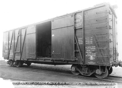
     To show what we’re talking about, here is a prototype 40-foot car when it was new, photographed by SP at Los Angeles shop in 1921. 


The “door and a half” design is evident, as are the end doors. The door opening as built was 10 feet, 5 inches, but in the early 1930s all these cars had their door openings widened to 12 feet, at which point they received a pair of equal-size doors. It is that modernized form of the car which Speedwitch modeled, with the interesting “steep” diagonal brace arrangement in the first panel to the right of the door.


This SP photo from Sacramento in 1933 shows a car with the wider doors and that “steep” brace.
     That covers what I wanted to say about using the SP Car Ledgers. Obviously the particular case of the A-50-4 cars is only one of many instances in which these ledgers provide far more information than usually available for freight cars.
Tony Thompson


Saturday, May 26, 2012

Waybills, Part 25: bill cycles

The concept of waybills controlling cycles of car movement is something familiar to any modeler who has operated freight trains. Some of these cycles are simple and easily explained, others can be complex. The modeling challenge is to reproduce them efficiently and realistically. In a previous post, entitled “Waybills-21: understanding waybill patterns” (view it at this link: http://modelingthesp.blogspot.com/2012/04/waybills-21-understanding-waybill.html ), I talked about fairly simple waybill cycles of loads and empties, simply moving in opposite directions over the layout. Here I would like to discuss more complex cycles.
     My examples in this post are from Frank Hodina’s new system. He is modeling a variant of the Chicago & Illinois Midland, which he calls the Chicago & Illinois Western, and it has the same kind of extensive coal traffic as did the C&IM. I showed one of Frank’s waybills in a previous post (available at: http://modelingthesp.blogspot.com/2012/03/waybills-20-other-approaches.html ). For his coal-handling cycle, cars are loaded at a mine, then weighed at a different location, then forwarded to destination. This means that a complete cycle for one of his coal gondolas uses several items of paperwork.
     The starting point for all of Frank’s freight car documents is the prototype. For example, here is a prototype C&IM waybill for coal from a particular mine. (You can click on any of these images to enlarge them.)


I won’t dwell on this waybill, but it will be evident in what follows that the model documents are closely patterned on it. The prototype is 8.5 x 11 inches, and to maintain those proportions, Frank’s model waybills are 4.25 x 5.5 inches.
     Frank’s model coal gondolas look like this, obviously drawn from the prototype C&IM. This is CIW 7084, for which the paperwork I’m showing was created.


We can begin with this car being loaded at a Peabody mine in Ellis, Illinois. The car is moved to Springfield for weighing, and the waybill notation says, “advise agent Ellis, Ill.” of the car weight. Note the colored box in the upper left corner of the bill. This is a coding for the destination, and is an aid to train crews. This waybill may be compared to the prototype C&IM bill shown above, and the many close similarities noted.


     Once weighed, the car is forwarded to Havana, Illinois (on the Illinois River) for transfer of its cargo to barges which will take the coal to the final customer, Consolidated Edison in Chicago. For that movement, a second waybill is used:


When the cars are unloaded at Havana, they are then sent back to Springfield to be held for loading. Thus the Empty Car Bill which is used only directs them as far as Springfield, from which they might be directed to any of several mines. Here is the paperwork:


When the car is selected to return to the Peabody mine no. 10 in Ellis, Illinois, another Empty Car Bill is made out for that movement.


     It is worth emphasizing that all these bills are, in a sense, conventional bills, in that they are documents for individual cars. Some of them are different from what most modelers are accustomed to, in that they document movements to destinations other than customers (in the usual sense of the term), but they are still individual car documents. In that sense, they resemble the Montour Railroad coal paperwork I showed in a previous post (see: http://modelingthesp.blogspot.com/2012/04/waybills-23-cuts-of-cars-update.html ).
     I emphasize this point because there is another side to this story, in handling cuts of multiple cars with single documents, an approach Ted Pamperin presented in his fine article in Model Railroader (February 2012, pages 45–49) and which I described in my original post on that subject (see: http://modelingthesp.blogspot.com/2012/04/waybills-23-handling-cuts-of-cars.html ). I will pursue further that side of the topic in a future post.
     But returning to the present post, to me, these model bills by Frank Hodina are an interesting and highly realistic reproduction of specific prototype patterns for freight car movement.
Tony Thompson

Wednesday, May 23, 2012

Survival from my old layout-2

Awhile back, I posted to this blog a general description of my old layout in Pittsburgh, and included information from an article about the layout in Railroad Model Craftsman, in March 1990. That prior post is accessible at this link: http://modelingthesp.blogspot.com/2012/03/survival-from-my-old-layout.html . I thought that post would summarize enough about the old layout as background for the layout work I’m now doing. But I continue to receive e-mail queries about the old layout, so I’ve decided to post a few more photos from those days.
     The most developed town was Jalama, as it was then called, which I now call Shumala (both are actual Chumash Indian place names). I described in an earlier post how I have “relocated” the area in which the layout is set; see: http://modelingthesp.blogspot.com/2011/01/layout-design-locale.html . In addition to the depot, ice deck and citrus warehouse, I had created a small business block. Here’s what it looked like (it’s now been modified somewhat). The “Giant Orange” stand was made from a European snack stand kit.


The “Buxom Melons” billboard is from an actual cantaloupe crate label.
     Near Jalama was a coastal scene, with the typical sandstone cliffs along which the SP tracks run, above the Pacific shore, in that area. I scratchbuilt a section house near the entrance to Tunnel 12. It’s shown here with a mainline freight train passing, powered by a Westside AC-4 locomotive:


Here is another view, taken by my wife to show me in the scene, dating from about 1986 (an era of large eyeglasses, among other things).


     The other town on the layout which had extensive development was Ballard, now being redone with a somewhat altered arrangements of industries. Photos of it may look familiar, because I have used a number of photos of Ballard, old and new, in previous posts on this blog. Here is an old one, showing a passenger train of my freelance short line, the Lompoc & Cuyama. The combine is a reworked LaBelle kit, named “Santa Ynez” for a river in the area previously being modeled. The car has a fully detailed interior and a removable roof, and did well in several model contests. It now resides in my display case.


    Another view at Ballard shows a meat reefer spotted at the wholesale grocer’s warehouse, Peerless Foods. This is a great industry for inbound loads, because everything from fruits and vegetables, to meat, poultry, eggs, dairy products, canned goods and other packaged foodstuffs, and dry goods can all logically be delivered here by rail. The structure was scratchbuilt from heavy artist’s cardstock and stripwood and, being near the backdrop, is a “half building” with no rear wall. At the time of this photo, door numbers had not been applied. In an earlier post, I used a modified version of this photo, in my post about making choices to select a fleet of refrigerator cars for the layout (see: http://modelingthesp.blogspot.com/2011/05/choosing-model-car-fleet-11-reefers.html ). This car was built and lettered by Richard Hendrickson and given to me.


     Last, I’ll show a photo taken by my friend C.J. Riley, about 1984, of me at my modeling bench in Pittsburgh. I can determine the date by the models being completed on the bench! Like many modelers’ work spaces, it wasn’t very large, but did have the advantage of storage space right above the bench, and shelves for reference books just at my right shoulder.


     Well, that should do it for an overview of the old layout, which like most layouts, had its attractions and its shortcomings. I believe the current version, as it’s progressing, is an entirely better version, but then, I would think that, wouldn’t I?
Tony Thompson

Saturday, May 19, 2012

The yard “jumbo”

In several places, including on this blog, I’ve referred to a kind of record book called a yard “jumbo.” One example would be my post about the handling of empties, at this link: http://modelingthesp.blogspot.com/2012/04/waybills-22-handling-empties.html . The “jumbo” was simply a book in which to record all cars passing through a junction point, in both directions. It not only created a record of the date and location of each junction passage, which was separately reported to the owner of each car, but also served as a record against which returning empties could be checked.
     This check was made because any empty being offered in interchange could be refused by the receiving railroad, if the car had not come through that junction in the other direction with a load. (For an explanation of this point, consult the post on empties, linked above.) How would you know? Easiest way, check the “jumbo.”
     A number of years ago at a Winterail event, there was a vendor with two “jumbos” for sale, both from the Bieber, California interchange between Great Northern and Western Pacific. One was for a couple months of 1947, as I recall (Richard Hendrickson purchased it, since he models 1947) and the other was for 1953, and I bought that one.
     I knew from talking to former car clerks why it was called a “jumbo:” because of its size. The covers of mine are 15 x 19.5 inches. Here’s my wife Mary holding it:


A plan view shows the cover, with its notation “JAN FEB 1953,” and the place name, BIEBER.


     The way these books were organized is interesting, because it reveals how clerks were accustomed to think of car numbers. The book is manufactured with tabs for numbers, every two digit number from 00 to 99. The leftmost row (toward the front of the book) is from 00 to 49, the right row for 50 to 99. Thus there are 100 tabs. The black tab contains the first digit, the yellowish tab the second digit.


These tabs together form the last two digits of a car number. If you go to such a tabbed page, it contains ten sections, each section having a different digit preceding the two tabbed digits. For example, if you go to tab 28, all the entry spaces are for numbers from 028 to 928. The clerk simply writes in all preceding digits, and the car initials.
     To describe the process of entering information, here is an extract from the book’s instructions (you can click on this to enlarge it):


If you would like to see the entire instruction document, I have placed it on Google Docs, at this link: https://docs.google.com/file/d/0Bz_ctrHrDz4wTWdjMWVGdWlKeVU/edit
     When you look up a car record, it’s the same procedure. Say the car is D&RGW 46628 (a GS gondola). You would go to the “28” tab and then on those pages, to the section for 628. It will be one of several cars with car numbers ending in 628, but now it’s a small group to peruse. Here is that number group:


The clerk has abbreviated D&RGW as “RG;” note also “AT” for ATSF.
     Under “Movements” are indicated the arriving train (by locomotive number) and date. For D&RGW 46628, the entries are: arriving Jan. 2, WP 923, departing the same day with GN locomotive 2002. The second entry, to the right, shows arrival on Jan. 12, GN locomotive 2021, departing Jan. 16, WP engine 918 (the delay probably means it was empty, but loaded vs. empty is not shown in these records).
     Further down this record, note SLSF 161628 (a box car), arriving Jan. 15 behind WP 916 and departing the next day behind GN 2017. What do we know about all these locomotives? The WP 913–924 series were EMD F7 diesels; the GN 2000 series were 2-8-8-0 articulated steam engines. Many GN 600-series locomotives are also listed in this book, and in 1953 these were EMD GP7 engines.
     Examples of this motive power can be discovered in published records. For example, here is a four-unit set of F7s, led by WP 923-D, passing Lake Almanor on the way to Keddie from Bieber. (Photo is by Western Pacific, from the Plumas County Museum collection in Quincy, courtesy Don Harris. The same image is reproduced on p. 94 of Norman Holmes’s book, My Western Pacific Railroad, Steel Rails West, Reno, 1996.) This is the locomotive identified for D&RGW gondola 46628.


     On the Great Northern side, the “jumbo” shows a mix of GP7 and 2-8-8-0 power. Here is an Al Phelps photo, taken on a bitter morning in January 1953, during the period of this particular “jumbo,” departing northward from Klamath Falls, Oregon (the first GN yard north of Bieber). Power is GN 2017 on the head end, assisted by a GP7. (Signature Press collection; this image is also in John Signor’s book, Southern Pacific’s Shasta Division (Signature Press, 2000), page 210.) This is the locomotive identified in the entry for SLSF box car 161628.


     Both these prototype photos were chosen, of course, to show engine numbers corresponding to the “jumbo” entries. The curious part of this, though, is that GN was operating scheduled freight trains on this line by timetable authority and train number, and WP was likewise operating most freight trains as scheduled train numbers. The reason the Bieber clerks used locomotive instead of train numbers is not known.
     One more point of interest. It may be noted in the book segment shown above that there is one car with four entries, which means passing through Bieber in both directions twice in these two months: refrigerator car FGEX 57628. This pattern of four entries in two months is seen occasionally throughout the book, primarily for reefers and for automobile cars and tank cars, which of course were largely in assigned service. Here’s an additional example:


The Associated Oil Company tank car AOX 1106 (with one entry for that same train on January 16 behind GN 2017, which contained SLSF box car 161628).  And reefer BREX 75106 also has four entries here. Note the abbreviation “RD” for SFRD.
     With that, I’ll wrap up this description of what I think is a fascinating chunk of railroad records. There are many data to be mined in this document, and as time permits, I expect to explore them. Any findings which seem appropriate for posting here will be reported.
Tony Thompson

Wednesday, May 16, 2012

Using model aircraft control linkage

My first exposure to model aircraft control linkage was in trying to simplify the switch machine connections for a double crossover in the hidden track on my old layout. This turned out to be one of those times you can benefit by wandering over to the “other side” of the hobby shop and having a look at the accessories for flying model airplanes. These linkage parts are intended to connect the control surfaces in the model airplane to the radio-controlled servos in the fuselage, and they are beautifully designed and built.
     The assemblies have nylon clevis connections for the servo, threaded steel wire for the long connection (4-40 threads if I recall correctly), and various bell cranks to transmit the desired motion. I purchased a handful of these parts and took them home to experiment. I quickly saw how nicely they can do the job, and went back to get enough more for my needs. I apologize that I no longer remember the brand name, but there are several brands out there today—try Googling the topic.
     Here is how the double crossover was linked when I was done. I had some old double-coil Walthers switch machines which were quite powerful (probably more than I needed), and wanted to see if they would work. Indeed they did. Here is a plan view of the completed linkage to one of the four switches; all four were similarly linked, to two switch machines, one on each side of the trackwork.


You can see here the flexibility of the parts, with the different adjustments to length and throw at the bell crank.
     The Walthers machine has a transverse brass throw bar, which moves back and forth horizontally in the photo above, and the bar has a hole in each end. It was easy to attach the nylon clevises, since they simply snap into these holes. I used a 6-32 screw up through the track board to pivot the bell crank, and set the height by arranging some nuts at the right height on this screw.
     Here is a closer look at the screw post, which could of course be arranged in a variety of ways. The nylon bell crank came with a brass bushing in it, to minimize wear, a nice design feature. The spring is a typical switch-machine connecting spring, of the kind used with twin-coil machines.


Finally, this may serve as a better look at the bell crank and its height adjustment screw (the nut beneath the bell crank can’t be seen here).  This linkage system was easy to install and easy to adjust, to optimize motion. In service, it proved utterly dependable and stable.


As I mentioned, this was hidden trackage, which is the reason for the gray-painted area immediately around the track, to suggest ballast, and the black color elsewhere.
     This is my only experience with this airplane control linkage arrangement, but I was most impressed and satisfied with the result. If you have a linkage problem anything like this, I would recommend you take a look at these convenient and well-made parts as candidates to solve the problem.
Tony Thompson

Monday, May 14, 2012

More on modeling the PFE car fleet

One of my earliest blog posts was about choosing a model car fleet, and I illustrated my points with the cars of Pacific Fruit Express. The prototype information used in that post was taken from the book, Pacific Fruit Express (2nd edition, by Anthony W. Thompson, Robert J. Church and Bruce H. Jones, Signature Press, 2000; the book can be readily ordered on-line at a variety of sites, including: http://www.signaturepress.com/pfe2.html ; scroll down to order). If you would like to view the earlier post, it can be seen at this link: http://modelingthesp.blogspot.com/2010/12/choosing-model-car-fleet.html . It’s mentioned there that I model 1953, so my choices in this post regarding car modeling are naturally directed at that year.
     In my talk about Pacific Fruit Express at the joint PNR-PCR convention a weekend ago, I talked briefly about the PFE car fleet in the same terms as in that original post, cited above. That was Part 2 of my talk. Part 1 of the talk was about PFE traffic to and from the Pacific Northwest. (The talk outline was shown in my post about that talk, which also links to the handout about PFE traffic; it, along with some brief remarks about the meeting, is at: http://modelingthesp.blogspot.com/2012/05/handout-for-pfe-traffic-talk.html .)  As a way to introduce Part 2, I showed the table below, which represents the core of my thinking on the subject. It contains data from the PFE entry in the January 1953 Official Railway Equipment Register.


The idea behind the right-hand column in this table is the proportioning of a model car fleet, by the ratio of one model car for each 1000 PFE prototype cars—give or take. Those values in turn identify the car classes you most need, and the numbers of cars from each class (those are the numbers in this column). Of course there is no need to be precise or even terribly consistent about these numbers of cars, and in reality a sample viewing along the railroad in 1953 would almost never be proportioned exactly by class size. But it’s a starting point.
     Here are a few of my models so far, to satisfy these needs. I do have several cars yet to do! To start, one of the largest groups, the 60,000 series, is represented by this R-40-19 car (an InterMountain RTR production version of Terry Wegmann’s excellent parts). I don’t yet have 6 cars in this series, but I’m getting close.


     Next is a stand-in for what is actually the biggest class group, the 91,000 series as it might be called, Class R-30/40-9. (This class, like several in the table above, was rebuilt from older cars of both R-30 and R-40 classes, thus this notation.) This car was modified from the Train Miniature wood reefer, and is scheduled to be replaced by a more refined model from Red Caboose. It is shown being spotted for icing.


     My table shows a need for five cars of Class R-40-10, and here is one of the ones I have completed so far, built from an InterMountain kit (shown at the winery in Ballard on my layout, picking up a cargo of wine in barrels).


     My table also calls for five cars in Class R-40-23. My version is again an InterMountain model, but this one was purchased RTR and then weathered lightly, since it is modeled with a later paint job than it had when it was new. It’s a load and is being picked up by the Guadalupe local after initial icing.


     The class following R-40-23 was R-40-25, a very similar car but with a diagonal-panel roof. My analysis calls for three of these cars. InterMountain has done this class also, as seen here in a passing train.


     One other class big enough to deserve three models is the interesting transition class R-30-16, with steel roofs and wood ends. My model, shown being switched at Shumala, is built from a kit by the late, great Terry Wegmann. You may have seen it in the posts that described construction of this model (see: http://modelingthesp.blogspot.com/2011/09/small-modeling-project-pfe-r-30-16.html ). I wanted to show my second model of this class, but it’s not finished yet! so I decided to repeat the older photo.


     Finally, the table includes a number of classes with fewer than three cars. I will just show a single example, a 47-foot car of Class R-50-5, built from a Sunshine kit. It is shown spotted for unloading frozen food at Peerless Foods in Ballard, the main use of this class after they were rebuilt with heavy insulation.


     As I stated, I am still working to complete the PFE model fleet that I want to operate, but things are coming along well. And since I am pretty much following the numbers determined from the table at the top of this post, I believe I am creating a good representation of PFE’s cars.
Tony Thompson

Thursday, May 10, 2012

Waybills, Part 24: routing

A question I have been asked, both in live clinics and after some blog posts, concerns how one determines routing of shipments, which would have been listed on waybills. (From the modeling perspective, this applies to creating accurate waybills, for those who find this topic interesting.)
    There are several obvious starting points, the best of which would be a file of actual waybills for your area and time period modeled. But very few of us have access to such a resource. Other rarely available but potentially rich sources include material from traffic officers who worked for shippers (paper or interviews), and railroad traffic analyses with data on junction activity—for which you would ideally have material from a whole bunch of railroads. Again, these are rarely if ever available.
     Here is what I’ve done. I start with the overall geography. I have a book of state railroad maps (a Kalmbach reprint of a Rand-McNally original), which helpfully shows main and branch lines with different line weights. It’s a 1928 document, so in some cases it’s necessary to be aware of later-day ownership and line changes. Here’s the cover of that Kalmbach book, which is often available from used book dealers on the Internet.


In addition to this version, there is also a 1948 edition of this book from Rand-McNally, available used on the Internet. I purchased it awhile back, and in truth it doesn’t add a great deal to the 1928 version. Or to put it another way, I think you can work equally well from whichever one you happen to acquire.


     In using either book I just try to see what routing could work, to make a more or less direct car movement. As another option, every railroad entry in the Official Railway Equipment Register has at its end a list of junction points, so you could use those to some extent, but you need to know where the lines themselves ran, and via which junctions.
     What about “approved routings?” Just as with tariffs, the ICC approved certain routings and not others. Especially in the eastern U.S., just about any possible routing would be an “approved routing,” so one can be reasonably prototypical with almost any choice. In the west, though, not all routings were officially “approved routings,” so you have to be more careful to use major interchange points. The “approved routing” books were regional and quite fat, and car clerks were expected to check waybills to ensure that routings were okay.
       General railroad knowledge helps too, such as knowing that UP received practically all its traffic from the east at Council Bluffs, or that both T&P and T&NO handed off westward traffic to SP at El Paso. For Chicago transfers, Jerry Stewart told me that routing would not ordinarily specify which railroad (EJ&E, IHB, etc.) would handle connections through the Chicago area, as that was up to local yardmasters and operating schedules, and the waybill would just identify Chicago as the junction. That’s what most of my waybills do also.
       From what former employees have told me, and what I’ve read, some shippers would let the agent choose the routing, or at least make suggestions, and naturally the agent would move the shipment as far on his own railroad as physically possible. But shippers had the absolute right to choose routing for themselves (still subject to being an approved routing), and large shippers typically had one or more traffic people who were responsible for getting shipments to customers. They might not use that much of their host railroad, if they believed some other routing would be faster or more dependable (or if they had some relationship to personnel on other railroads). That’s why you really can’t know for sure how most cargoes would be routed.
     Given all this background, here is a single example from my layout, of a waybill for a reasonably long-distance shipment. 


Junction points shown here are at Bluffton, Ohio (BLF), St. Louis (STL), Corsicana, Texas (COR), and El Paso (ELP). Is this accurate? I don’t know, but I believe it to be reasonable. The typeface in the body of the waybill, incidentally, is American Typewriter.
     Not everyone will find this topic interesting, but if you do, as I do, it’s a gratifying and enjoyable effort to construct realistic routings for your model waybills, and of course to fill out the waybills accordingly.
Tony Thompson

Tuesday, May 8, 2012

Handout for PFE traffic talk

At the just-concluded joint convention of the Pacific Coast and Pacific Northwest regions of NMRA, held in Medford, Oregon during May 2 to 5, I gave an invited clinic about PFE traffic. The goal was to address PFE’s traffic volume and content to and from the Pacific Northwest, obviously a suitable topic for such a convention. (The Pacific Coast Region includes Northern California and Nevada, plus Hawaii; Pacific Northwest Region includes not only Oregon, Washington, Idaho, Montana, and Alaska, but also the Canadian provinces of British Columbia, Alberta and Saskatchewan.)
     I did not prepare a paper handout for the talk, but told clinic attendees that one would become available on line. This post makes that handout available.
     Only the traffic part of my talk is described in the handout, and the sources of data are shown, along with numerical and proportional conclusions about modeling this PFE traffic. The primary background, as might be guessed, is the PFE book (Pacific Fruit Express, 2nd edition, Anthony W. Thompson, Robert J. Church and Bruce H. Jones, Signature Press, 2000). The handout document is on Google Docs, at this link:

https://docs.google.com/open?id=0Bz_ctrHrDz4wMTAxUzNEQnNIclk

Anyone is permitted to read, download, or print this document, as they wish. I hope it is helpful and informative.
Tony Thompson

Monday, May 7, 2012

My column on Waybills in Model Railroad Hobbyist

Probably most readers of this blog know that there is an electronic magazine out there, called Model Railroad Hobbyist or MRH, now issued monthly. It covers a range of topics every month, and can be downloaded free at: http://model-railroad-hobbyist.com/magazine/mrh-2012-05-may .
     Fewer readers perhaps realize that I am part of a cycle of writers who sequentially produce a column called “Getting Real,” about prototypical modeling (the others include Jack Burgess, Mike Rose, Marty McGuirk, and MRH publisher Joe Fugate). The latest issue, for May 2012, was released today and has my latest column in it, all about model waybills. It really will have little new in it, for anyone who has read and digested the various posts on waybills of this blog, but does collect in one place a whole range of ideas, and includes some new waybill images and model photos. If you would like to check out the magazine, the link above is to the site from which you can download the May issue.
     The article generally turned out well, and for the most part I like the way it is laid out and presented. (I would not have used tinted page backgrounds, but that’s another discussion.) The only problem I’ve seen is that in modifying my original figure numbers, they lost a figure. Using the figure sequence in the article, it should lie between Figures 22 and 23, so maybe it could be called Figure 22B. You can see the omission when you read the caption for Figure 23, which says “Here is that lumber load,” but no other information is given. Here is what was supposed to precede Figure 23, what I just identified as Figure 22B:


The caption for it reads, “Waybill, 2 x 4-inch format, for a load of lumber in a gondola.”
     The error, of course, is not serious and I only correct it here for completeness, Writing this column has proven to be an interesting exercise and I’m looking forward to future columns.
Tony Thompson

Tuesday, May 1, 2012

Handout for Waybills talk

I have usually distributed paper handouts at talks, but a multi-page handout gets a bit expensive to reproduce and bulky to transport. It may also run out if I haven’t correctly predicted the audience, and in some cases people who weren’t able to attend the talk in person would like a copy. For all these reasons, it seems to me that what might be called a “back-up copy” on the Internet is a sensible idea.
     For my current waybill talk, I have made a PDF version of my usual handout, and have placed it on Google Docs, where you are free to download it if you like. Here is the link:

https://docs.google.com/file/d/0Bz_ctrHrDz4wcjJObUFxVG0xTzA/edit .

     The handout document contains a brief text summary of several points which are made in the talk, has a summary Car Service Rules page, and a few examples of my current waybills, along with a fairly complete bibliography. It also offers copies of two prototype waybills, one of which is the Illinois Central one with all the stamps and handwriting on it.
     It is worth mentioning that all the material in this handout has been discussed in a series of posts to this blog, so regular readers will find nothing new. But it does collect the core topics of the oral talk in one place. Hopefully this is an added convenience for some readers.
Tony Thompson