Saturday, August 29, 2015

Modeling SP MOW cars, Part 4

In an earlier series of posts, I described some of the Maintenance of Way (MOW) cars I have modeled, following SP practice, for my layout.  I began with a box car and tank car (for domestic water) in my first post (it’s at: http://modelingthesp.blogspot.com/2013/03/modeling-some-sp-mow-cars.html ). The second post described modeling a truss-rod flat car and an on-line ice-service car, made from a former PFE car (you can find it here: http://modelingthesp.blogspot.com/2013/04/modeling-some-sp-mow-cars-part-2.html ). The third post covered a former passenger car converted for MOW use, starting from a Roundhouse “old-time” baggage car (it can be seen at this link: http://modelingthesp.blogspot.com/2013/04/modeling-some-sp-mow-cars-part-3.html ), though in fact this Roundhouse model as originally configured is much more like an RPO car.
     In the present post I want to expand on this, to some additional cars. A car type which is very well represented in SPMW rosters (see the first two posts in this series, links provided in the paragraph above) is box cars. Essentially the track forces acquired these cars by keeping in contact with the Mechanical Department, and arranging to choose the best available in a group being scrapped. Often the chosen car(s) would then get an overhaul and fresh coat of paint, but sometimes if needed immediately might only have reporting marks changed and then pressed into service. I have modeled both kinds of paint schemes.
     I show below two models built from Westerfield kits, both of the body style typical of Harriman Lines Common Standard classes B-50-2, -3 and -4. Built from 1906 through 1909, there were more than 10,000 box cars in these three classes. more than 7000 of them for the SP and T&NO railroads. They continued as major players in the Southern Pacific boxcar fleet until about 1930,w hen their numbers began to decline precipitously. By 1940, they became rare in revenue service. (For a fuller history, see Chapter 6 in my book, Southern Pacific Freight Cars, Vol. 4, Box Cars, Revised Edition (Signature Press, 2006 and 2014.)
     As soon as these cars began to leave the revenue-car roster, of course, maintenance people were selecting the soundest cars for their own use. SP rosters of MW cars do show many box cars from these classes converted to MW use in the late 1920s and during the 1930s, exactly while their revenue numbers were falling sharply. So if a modeler of the 1950s, like me, wants to operate one of these fine Westerfield models, it will have to be as a member of the SPMW roster.
     Here is one example, depicting the kind of car that would have been pressed into service without repainting, leaving the former SP emblem still on the car, but with a paint patch for the SPMW car numbering.


     More commonly, though, the MW people would have gone over the car to make sure it was mechanically sound, made any modifications they desired, and then would have given it a fresh coat of paint, with no visible indication of its former status in a revenue paint scheme. What would that look like? Here is an example of one such car, which has received an end door and a ladder and a sill step alongside the side door (the same photo was included in the first link cited at the top of this post). The photo is from the Arnold Menke collection, location and photographer unknown. Note that the only item of dimensional data is the light weight. The SPH&TS roster shows that this is a former B-50-2 car, number 89084, converted to MW on December 30, 1944.


     My model is patterned after this paint scheme, though I left the model without the kinds of body modifications shown above. I also happen to have chosen a very interesting Westerfield kit here, which models the one and only SP car to receive a Van Dorn pressed-steel end (kit 1761). I showed two views of the prototype car in an earlier post (you can see it at this link: http://modelingthesp.blogspot.com/2015/08/using-prototypes-older-than-your.html ). This model too was given the very Spartan kind of lettering shown above on SPMW 3566. It is shown in the photo below on the outfit track in my layout town of Ballard. (You can click to enlarge.)


     Both these box cars can be operated with waybills for such cargoes as track materials and supplies. Another common load would have been track tools for use on some roadway maintenance job. Here is just one example of the waybills for MW box cars in use on my layout; note that it is prominently marked as a “non-revenue” bill.


     These box cars are useful as part of the overall layout operation, because of course they are part of the work of the railroad. Having set aside an outfit track in my town of Ballard, they have a place to go, and sometimes a place to remain through several operating sessions. Just like the prototype.
Tony Thompson

Wednesday, August 26, 2015

A Union Oil Company bulk dealer

I have written several times about my creation of an Associated Oil Company bulk dealer in my town of Shumala, most completely in my “Getting Real” column in Model Railroad Hobbyist, the issue for March 2014 (you can download this or any issue of MRH from their site at: www.mrhmag.com ). But in the era that I model, the 1950s, most small towns had at least one bulk oil dealer, often two or three for the various major brands. I decided to have one in the name of a prominent West Coast oil producer, Union Oil, in my town of Ballard.
     I began with a Chooch kit for an oil dealer (no longer in production). It provides two vertical tanks and a tank enclosure or berm, along with a pump house and some molded oil drums scattered about. These parts are nicely done, but are nowhere near enough to represent a real oil dealership. My first step was to figure out how to add another large tank and some smaller tanks. I used stripwood to build additional tank enclosure in the style of the kit berm, added a medium size tank, and put together the typical ladder and stairway connections to permit access to the tank tops. Here is a view of those additions, with the original Chooch kit base glued to a larger piece of 0.060-inch styrene.


In this view, the blank space on the right is the location of the warehouse and office building, essential to any oil dealer. The stairway is mostly scratchbuilt out of styrene sheet and strip, with the stairway and its railings from the Central Valley Stairs and Ladders set.
     From the front, the three major tanks are visible, along with the small pumphouse at right, that was supplied in the kit. The various molded-on oil drums are evident here, though it seems improbable to me that drums would actually be strewn around like this. Still, they help identify the business. I added a small Union 76 emblem on one tank.


     Since a warehouse/office is essential, I simply scratchbuilt one from Evergreen styrene clapboard sheet, with Pikestuff shingle material for the roof. Interior corners of the structure received styrene strip reinforcement, as you see here.

When completed, this simple building is all set to be a vital part of this complex. Windows are Grandt Line. I chose to use the blue trim color on the building corners here.


      This warehouse is scaled to fit alongside the Chooch base, and the trim and windows pick up the same blue colors seen on the pump house and some barrels. The company sign on the roof was printed out in blue, and was framed with strip styrene. When the entire complex is put together, it looks like this, seen now from another angle.


For a view of this dealership in a prior location on the layout, you can visit this post: http://modelingthesp.blogspot.com/2012/03/tank-car-placards-modeling.html .
     On the layout, this small dealership looks fine, and in additional to the usual tank car unloading that is naturally associated with such a business, there is also a warehouse door at trackside for the unloading of drums of oils and lubricants, along with cartons of consumer products, particularly cans of motor oil, grease containers, and so on. This is thus an industry that accepts different kinds of freight car loads as well as being a typical small-town business.
Tony Thompson

Sunday, August 23, 2015

Handout for oil dealership clinic

This handout post was prepared for a clinic I have presented, starting in 2015, entitled “Building a Realistic Bulk Oil Dealership.” There really need be no formal handout, but a few factual parts of the clinic may be worth having in written form.
     Three oil companies are represented, Associated Oil, Union Oil Company, and Standard Oil of California.
     The core of the construction of the Associated Oil Company dealership was described in my Model Railroad Hobbyist article, cited below in the list of publications. In that article will be found all specifics of model parts and materials for that project. The Union Oil dealership was expanded in a simple way from the original Chooch kit (no longer in production), and details of that expansion are also being included in separate posts to this blog. My Standard of California “minimalist” dealership primarily used duckboards to create its presence; there is a separate blog post for modeling duckboards, and it is at this link: http://modelingthesp.blogspot.com/2015/08/duckboards.html
     I mentioned several published items in the talk. Here is a list.

•  Jeff Wilson, The Model Railroader’s Guide to Industries Along the Tracks, Kalmbach Publishing, 2004. (Also available as a Barnes & Noble e-book in NOOK format)
 
•  Robert Schleicher, “Standard Oil Co. Depot at Waterford, California,” Railmodel Journal, April 1996, pp. 14–22.

•  Olaf Melhouse, “Modeling the Oil Industry: Texaco Bulk Oil Depot at Devils Lake, N.D.,”   Railmodel Journal, December 1994, pages 12–18. 

•  Gerald T. White, Formative Years in the Far West [history of California oil companies prior to 1919], Appleton-Century-Crofts, New York, 1962.

•  Frank J. Taylor and Earl M. Welty, Black Bonanza, McGraw-Hill, New York, 1950 (reissued with revisions in 1956 and 1958).

•  Earl M. Welty and Frank J. Taylor, The 76 Bonanza, Lane Book Company, Menlo Park, CA 1966 (1976 revised edition by Niven and Waddell entitled Sign of the 76). 

•  Anthony Thompson, “Modeling a bulk oil dealer,” Model Railroad Hobbyist, March 2014. (You can download this any time from www.mrhmag.com )

•  Anthony Thompson, “Associated Oil Company—background,” blog post, at this link: modelingthesp.blogspot.com/2013/12/associated-oil-company-background.html 
 
•  Several subsidiary topics in this clinic have been explored in more detail in my blog, most easily found by the search box at top right. For future reference in reaching this blog, I recommend Googling “modeling the SP,” then using the search box. 

     As always, I will be happy to answer questions, either directly to me outside the blog, or directly as comments and responses on the blog itself.
Tony Thompson  

Thursday, August 20, 2015

Discovering a Tony Koester book

Tony Koester, in addition to his duties writing a monthly column for Model Railroader entitled “Trains of Thought,” and editing Kalmbach’s annual Model Railroad Planning, also writes about a book a year for Kalmbach. These range over a variety of topics (Tony may even get to choose at least some of the topics), and most are interesting and well worth reading. But recently I came across one I didn’t even know about. It’s entitled Model Railroading from Prototype to Layout, and was published in 2010. I promptly bought it.


As you can see, this copy is a little shopworn and was the only remaining one in the bookstore at the California State Railroad Museum (I was there for a committee meeting). And as happens with Kalmbach often enough, it’s out of print from the publisher, though it can readily be found from used book dealers on line.
     On the Capital Corridor train returning from Sacramento to Berkeley, I devoured a lot of the book, and since then have been enjoying rereading some parts of it more thoroughly, and taking time for the requisite amount of thought about the many points Tony makes in the book. I only get more impressed as I do so.
     All of Tony’s books are interesting, because he has thought a lot about many issues in the hobby, and is a good writer who conveys clearly what his points are. Some of the wisdom in this particular book I recognize from some of Tony’s past clinics (more on that in a moment), but the biggest feature for me in this book is how much is brought together — prototype choices, layout choices, rolling stock choices, operations choices, and so on. It really is about the entire hobby, and as always with Kalmbach, beautifully illustrated.
     The core idea promulgated in the book is the variety of ways to accomplish prototype modeling. Tony emphasizes, and states it more than once, that prototype modeling is much more than building accurate models of prototypes. Prototypical choices of layout locale and structures, as well as prototypical kinds of trains and train operation, along with consistency of era, are also important parts of the idea.
     The book chapters suggest how wide-ranging the content is. The book has an Introduction and nine chapters. They are titled as follows: What is “prototype modeling?”, Choosiing a prototype to model, What time is it?, Structures and scenes that look the part, Putting the (iron) horse before the cart, Modeling jobs, Prototypical approach to layout design, Coping with space constraints, and Prototype modeling sampler.
     The breadth of content is suggested by the chapter titles, but probably they can’t convey the depth. This is one of Tony’s strengths for me, the depth of thought that comes from so many years in the hobby, and from jobs like editing Railroad Model Craftsman, before becoming a Model Railroader columnist. And as I said, he conveys his thoughts clearly and convincingly. Not that I agree with every point, only that every one, for me at least, is definitely thought-provoking.
     Even more than most of Tony’s books, and because of the sheer breadth of the subject matter here, this one could certainly be subtitled “the wit and wisdom of Tony Koester.” It’s an impressive and memorable book, and as you can tell, I like it and recommend it unreservedly. If you don’t already have a copy, it’s worth making the effort to find one, either on line or in a shop with slow sales (as I did). But get one.
Tony Thompson

Monday, August 17, 2015

Using prototypes older than your modeling era

Many of us who are model builders at heart hate to face the fact that some interesting and desirable models are simply of too early a period to make sense. If you model, say, 1953, as I do, you may love diamond-stack 4-4-0 locomotives but they are just not going to be credible on the SP in California in 1953, The same goes for early freight and passenger cars, even structures which may no longer exist in 1953.
     But in some situations there can be an “out” for the nostalgic modeler (relative to the chosen modeling period, that is). Like most railroads, Southern Pacific did roster a considerable fleet of maintenance cars, some of them naturally purpose-built, but many merely hand-me-downs from the fleet of revenue freight (and passenger) cars. So clearly one way to be able to both build and use models of earlier eras would be to see how they were used in Maintenance of Way (MW) service.
     For me, one such very attractive and interesting group of “too old” prototype freight cars comprises the Harriman car designs, so called because they were built under Common Standards for both Union Pacific and Southern Pacific during the Harriman Lines era. Most of these cars had pressed-steel underframes and wood-framed superstructures, so their life would necessarily be limited by survival of the superstructure. And indeed, though many survived through the 1920s after construction during 1906–1910, they began to be scrapped in quantity after 1930. No doubt the Mechanical Department and the shops were unwilling to rebuild wood superstructure framing in kind by that date, but such a car could be refurbished and perhaps modified as needed for MW service.
     I have already talked about this process in describing my use of a Westerfield kit for the early PFE refrigerator Class R-30-2 (kit 1802). I helped Al with prototype information in developing this kit, and in return he sent me a free kit. Well, this class of cars was long gone in revenue service by 1953, but I did know the SP had bought ten of these cars in the 1930s, so built the kit and decorated it as one of those SPMW cars. I showed the result in a prior post (at: http://modelingthesp.blogspot.com/2013/04/modeling-some-sp-mow-cars-part-2.html ).
     Another example of this process was supplied in another post, in which I used the Westerfield kit for Harriman Class B-50-2 to model an MW car, SPMW 2621 (that post is at this link: http://modelingthesp.blogspot.com/2013/03/modeling-some-sp-mow-cars.html ). As explained in that post, the car number is that of an actual B-50-2 car which was converted to MW service. A photo of the completed car is in that post also.
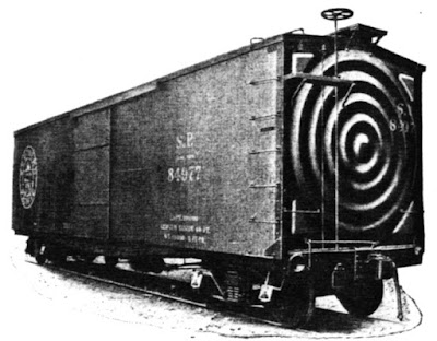
     But I wanted to do another such car for MW service, a desire stimulated by the beautiful kit Al Westerfield produced of the one and only SP car which received a Van Dorn pressed steel end (Westerfield kit 1761). Here is a prototype photo of this unique car.


This isn’t a great image, but shows clearly the B or brake end of this one car, SP 84977. Below is a view of the A end, interesting because of the lumber doors which had to be fitted to the shape of the end stamping.


Note how the end lettering is applied over the ridges in the stamping. The car itself was built in August 1906, and was chosen in 1910 for a retrofit of this newly manufactured car end. The ends were applied in May, 1910, and the car survived in revenue service until it was declared “worn out” on March 29, 1939 at Los Angeles. Though this probably meant the car was scrapped at that time, it is also possible that it was transferred to MW service instead. I don’t find this car number, SP 84977, as a former car number in any MW roster, but these rosters did come and go, so I have decided to believe the car was so converted, at least for a time. Certainly if it survived 1939 in any form, it would have to have been as MW.
     In particular, with Westerfield’s superb molding of this remarkable end, I can arrange for SP 84977 to live on in MW service, though of course with an MW number. Here are two photos of the model, assembled by Dennis Williams and lettered by me, first showing the well-rendered A end. I applied the end lettering as in the prototype photos. The sides and ends are not yet weathered.


The B end lacks the doors, but has all the brake step and handbrake attached over the ribs, in some ways even more complex than the A end. You can see those details here.


     Though the prototype of this Van Dorn car may have been scrapped by my modeling year of 1953, I have kept it alive in MW service, as just another roadway box car. I will discuss in a future post the MW and operation side of the modeling.
Tony Thompson

Friday, August 14, 2015

Duckboards

I was once holding forth on this topic in a small group of modelers and one said, “What the heck is a duckboard?” That is, of course, a perfectly reasonable question, and the easiest answer is that it describes slatted wood panels, often used to ensure good footing in swampy, oily or otherwise treacherous ground. The origin of the term seems not to be known firmly (you can walk like a duck in muddy ground?), though the term gained widespread notice in the trenches of World War I. The problem there was that water tended to stand perpetually in the bottom of trenches, and duckboards placed there mostly kept the soldiers’ feet out of the mud. There is an informative if brief Wikipedia summary at: https://en.wikipedia.org/wiki/Duckboards . It’s been true for years that hiking trails traversing swampy areas may improve the footing with stretches of duckboard.
     But what has that got to do with modeling or the Southern Pacific? Answer is, SP used duckboards all around the system. Here is one example, taken in the engine facility at Taylor Yard (Los Angeles) in July 1950 by Richard Steinheimer. The negative is in the DeGolyer Library at Southern Methodist University, from whom permission to publish was obtained.


This is an area where running gear of steam locomotives was steam cleaned, naturally making the ground wet, and blasted-off oil and grease doubtless made it even more slippery. The duckboards would help workmen move safely and comfortably along these tracks.
     Here is another example, concerned more with oil spillage. It’s alongside the fuel track at San Luis Obispo, where diesel fuel was unloaded from tank cars. In fact the two tank cars visible in this view have their bottom outlets connected to intake valves by means of hoses. This is a Southern Pacific photo, probably from 1954 or 1955. (You can click to enlarge.)


Notice the similarities in duckboard dimensions and arrangement to the first photo, but also notice in both photos that some of the duckboard panels are not perfectly aligned with their neighbors.
     Now if one wanted to model this kind of scene, what would be an easy way to do so? Obviously these duckboards could easily be scratchbuilt with stripwood or strip styrene, though it would be a tedious process and likely not easy to get the boards consistently parallel. I’ve adopted a much easier way. I use HO scale pallets. There is a Preiser set of pallets, their number 17104. You can Google “Preiser 17104” and find lots of resellers of this pallet set. My box looks like this:


Note that you get 60 pallets in this set. The cover artwork shows a color that is more yellow than the models, but the as-molded color is definitely a new-wood color.
     I should point out that these are “Euro-pool” or EUR-pallets. They are narrower than standard American pallets, so may not suit you to stack on loading docks of your layout industries, but they are fine for duckboards. (The EUR-pallet is 1200 x 800 mm; standard U.S. pallets are 40 x 48 inches, or 1020 x 1220 mm. Today there are several additional standard EUR pallet sizes. If this topic is of interest, Google “EUR-pallet” for more information.)
     I have made duckboards out of these pallets by lightly priming them first, usually with gray or light brown, sanding the bottoms, and attaching a strip of thin styrene sheet or sometimes a scale 1 x 10-inch styrene strip, to hold them in alignment. Here are two sets of duckboards, one upside down to show the 1 x 10 I used in this case. The irregularity is deliberate; one could certainly align them very precisely if desired.


These duckboards are only primed, and certainly will be given oil stains and deposits before installation on the layout, but show the kind of model you can produce.They have and should have gaps between all boards, which is an effect you would not get with scribed styrene.
     As the prototype photos indicate, both engine terminals and oil unloading spots are good places to use duckboards. I plan to do both, and will report in later posts on their placement.
Tony Thompson

Tuesday, August 11, 2015

Waybills, Part 43: Operations with MOW cars

In an earlier series of posts, I described some of the Maintenance of Way (MOW) cars I have modeled, following SP practice, for my layout. Those posts were in March and April of 2013, and can readily be found by using the search box to the right. In this post, I want to say a little about how these cars are operated on my layout.
     I will begin with ballast cars, since these are often present in photos of any roadway maintenance scene. I have discussed SP ballast cars in a post back in 2011 (here’s a link: http://modelingthesp.blogspot.com/2011/03/choosing-model-car-fleet-7-hoppers.html ). Here I will only mention my stand-in for a Class H-50-6 Hart Selective ballast hopper, modeled from a standard Athearn twin hopper, with added styrene to model the longitudinal dump doors (though they are oversize). The slope sheets should reach nearly the top of the car side, not have the lower-angle slope seen here, but that would represent a lot of kitbashing to get right. These cars were still classified by SP in 1953 as AAR Class MWB, though they carried revenue-service car number series. In the spring of 1956, SP would discontinue use of the MWB classification, and re-classify all cars like this as AAR Class HK. But as a 1953 modeler, they are still MWB cars to me.


In addition, Southern Pacific commonly moved roadway ballast in drop-bottom or GS (General Service) gondolas, and I have made a couple of ballast loads for my GS gons to serve this purpose. Whichever kind of car covers the ballast moves, a waybill like this is used (based on what I was told about how these loads were moved), since I have an outfit track at Ballard on my layout.


It’s well known that much of SP’s Coast Line ballast came from the Granite Rock quarry.
     When SP used GS gondolas to transport ballast, they tended to be the Enterprise steel cars built in the 1920s. I have a number of these in my fleet, and any one might be chosen for a ballast delivery in a particular session. I have removable loads for these cars (built by the methods described in a previous post, at: http://modelingthesp.blogspot.com/2012/02/open-car-loads-bulk-materials.html ). Here’s a photo.


The car is shown on the outfit track in Ballard on my layout. The MW-converted passenger car at right was described in an earlier post (see it at: http://modelingthesp.blogspot.com/2013/04/modeling-some-sp-mow-cars-part-3.html ).
     A waybill for a ballast load in a GS gondola, then, might look like this.


Obviously the same source and same destination, but in a different car type.
     Though MOW cars are not likely to be a big proportion of any layout’s car fleet, they do have a role to play, and including that role diversifies the car movement patterns that operators experience. I plan to add more waybills for MOW car activities in the future.
Tony Thompson

Saturday, August 8, 2015

Small modeling project: a yard limit sign

As operators can read in my timetable for the Guadalupe Subdivision of SP’s Coast line (adapted from the prototype for my layout), the entirety of the location of Shumala is in yard limits. Here is the relevant part of my timetable adaptation:

Shumala depot is at milepost 270.1. I described preparation of my layout’s timetable in a column for Model Railroad Hobbyist back in October 2014 (downloadable at www.mrhmag.com), and summarized it in a previous blog (see: http://modelingthesp.blogspot.com/2014/10/my-column-on-timetable-construction.html ).
     Placing the Shumala trackage within yard limits simplifies switching because Rule 93 was as follows (every railroad worded it a little differently, but this very clear statement is a Santa Fe version):

     “Stations having yard limits will be designated by special rule in the timetable.
      “Within yard limits all trains and engines may use the main track, not protecting against second- and third-class trains, extra trains and engines, but will give way as soon as possible upon their approach. All except first-class trains will move within yard limits at restricted speed; the responsibility for accident with second- and third-class trains, extra trains and engines rests with the approaching train.”

     But although the yard limits on the SP main track at Shumala extend in both directions beyond what is visible on the layout, that is not true for the track of the Santa Rosalia Branch, which leaves the SP main at Shumala to head down the branch. In the absence of an actual yard limit sign, I have been verbally informing operating crews where that sign should be located. I think it’s now time to install a physical sign.
     There was (as you would expect) a Common Standard for yard limit signs; the one shown below was published on page 31 of Southern Pacific Lines Common Standard Plans, Volume 1 (Steam Age Equipment Company, Dunsmuir, CA, 1992). This particular drawing is a 1963 revision of the original standard arrangement, which among other things specifies aluminum blades. But the sign geometry and mounting are clearly shown, so I can readily back-date this item to the wooden sign era. Blades are 8 inches wide and 2 feet, 6 inches long to their longest point. (You can click on the image to enlarge it if you wish.)


One point of possible era confusion from the 1963 drawing, is the instruction that blades are to be yellow. I have not found a transition-era photo showing an SP yard limit sign which is clearly other than white, so could choose to make mine white, but in the absence of evidence other than the drawing above, have decided to go with yellow.
     The simplest way to make a sign like this is just to reduce the drawing above to HO scale and print on light card stock. The blade length, 30 inches, is 0.34 inches in HO scale (divide by 87). I did that and prepared a scale 4 x 6-inch piece of stripwood for the post, painted dark brown. The blades are just the cardstock I printed out. For the choice of yellow blades, I could do it by using a yellow “highlighter” felt pen on a white cardstock sign, or simply use yellow cardstock, which I ultimately did.
     The sign was glued to the 4 x 6-inch post with canopy glue, then inserted into a hole alongside the track, also with canopy glue, and adjusted so the top of the post was 9 scale feet above the ground, as called out in the drawing above. Here is the installation, with Chamisal Road in the background.


     Now I won’t have to point to the yard limit spot when operating crews approach Shumala from Ballard; I can just remind them to look out for the yard limit sign. Gee, just like the prototype.
Tony Thompson

Wednesday, August 5, 2015

Western Packing Company

I have always been intrigued on layout visits to see industries which from the layout aisle are cutaway or one-wall, open-interior buildings which you view from inside, looking out through the loading doors, for example the hardware warehouse on David Doiron’s layout in Phoenix, Arizona (I showed a photo of that structure in my post about operating on that layout, http://modelingthesp.blogspot.com/2012/11/layout-visit-interesting-industries.html ). This is not a new idea, of course; I also clearly remember an interesting article in Model Railroader, way back in 1993, entitled “Build a see-through freight house,” by John McKeeman (August 1993, page 64).
     Probably it comes as no surprise that my plan to have two packing houses at my layout town of Ballard was running afoul of sheer space limitations. But the cutaway or front-wall-only design held out the possibility of an industrial structure with no footprint on the layout other than its loading platform. The idea is kind of like a flat, except at the front edge of the layout instead of against the backdrop. Model structures like this are sometimes called “fascia flats” to describe their location.
     In fact, using a vertical sheet of clear plastic as the “structure,” I would only need to create the inside of a wall (on the layout side of the plastic) and add a platform. The interior wall could be sheathed or even plastered, but it would be more interesting to show it as open framing. Doing that means that you have to get the framing details correct. For anyone not entirely up to speed on construction details, there is a superb book out there, Building Construction Illustrated, by Francis D.K. Ching, originally from Van Nostrand Reinhold and now a Wiley book (available in paperback or e-book format: http://www.wiley.com/WileyCDA/WileyTitle/productCd-1118458346.html ). This is how the current 5th edition looks.


The background drawing on this cover illustrates the kind of material in the book. With this kind of book in hand, I felt confident I could do accurate framing, but so far I still have not made a final decision whether open framing is the appearance I want.
     Whichever interior wall treatment I choose, I have enough space to include a little of the inside floor of the structure, thus permitting stacks of shipping boxes and similar details. I plan to make up some HO scale packing box labels to enliven the boxes. Here is one of the vegetable labels used by the prototype Western Packing Company. Reduced to HO scale, I think these will look fine on boxes.


This is not the only label used by Western Packing, but it is a colorful and appropriate one that I can use on a loading dock.
     That said, my first step was to acquire the piece of clear plastic for the layout edge. I can’t speak for other parts of the country but here on the West Coast, we have TAP Plastics. They not only sell all kinds of plastic in sheets and other shapes, but will both custom-cut to size and also edge-polish (for a fee, of course). I went ahead and ordered a suitable piece of 1/4-inch acrylic about 4 x 14 inches to provide plenty of space for the packing house, allowing for the width of the fascia alongside the future location of the packing house. And the 14-inch length was chosen to allow spotting of three reefers at once for loading.
     So with a size chosen, plenty of space on the relevant spur track, and an idea of what I want to build, along with that critical piece of clear plastic, I think I am about ready to go ahead with this project. More later.
Tony Thompson

Sunday, August 2, 2015

The new Kadee LPG tank car

Many readers by now will know about the new Kadee freight car, an insulated high-pressure car of the kind predominantly used for LPG (Liquified Petroleum Gas) in the transition era. The same size car could also be used for chlorine and anhydrous ammonia. This particular model is ICC Class 105A300W, as built by American Car & Foundry during the years 1947–1950, with what AC&F termed a Type 27 underframe. More than 1650 of these cars were built in that time period.
     As one expects of a Kadee freight car, the model is exquisite. Here is a photo of the car I just received. (You can click on the image to enlarge it.)


This car is lettered for Tidewater Associated Oil Company, and uses the TWOX reporting marks identified with the Eastern Division operations of the company, headquartered in New Jersey. However, the company freely used its cars as needed throughout the country. I have written previously about the history and operations of this oil company, if you’re interested in that (see this post: http://modelingthesp.blogspot.com/2013/12/associated-oil-company-background.html ).
     In the period after World War II, the growth in LPG traffic was, to choose a delicate word in this topic area, explosive. In an effort to speed up return of empty LPG cars for loading, the suggestion was made to paint their valve bonnets white, as you see on this car. (This was not mandatory, and not all operators of LPG cars did this.)
     One characteristic we have come to expect on Kadee rolling stock is outstanding printing of the lettering. This car is no exception. Below I show the right end of the car side, with the various specifics of lettering about car construction and inspection.


The shadow in this photos, incidentally, shows you that the running board represents see-through metal grid and is beautifully rendered.
     I have an Associated Oil dealer on my layout (the Associated Oil Company became in 1926 the Associated or western Division of Tidewater Associated Oil), so I can deliver LPG there in this car. I have posted previously about the  construction and operation of that dealership model (see it at; http://modelingthesp.blogspot.com/2014/03/more-on-associated-oil-dealer-model.html ).
     I don’t know what lettering schemes Kadee has in mind for the future of this model, but as always they will be carefully researched and accurate. Unlike most manufacturers, Kadee does not letter models for owners which did not own or operate that particular car, so you can trust any version they may choose to do. For myself, I am certainly delighted with this one, and look forward to seeing what comes next.
Tony Thompson