Tuesday, July 29, 2014

Modeling SP head-end cars, Part 7A: postal storage

One car type often seen in the Southern Pacific’s transition-era “Coast Mail,” trains 71 and 72, is a postal storage car. This was a car with nothing inside but vertical stanchions, floor to ceiling, to which mail bags could be tied. Sometimes it was a working car, adjacent to the RPO (Railway Post Office car), sometimes it was a sealed car of through mail (mail in closed pouches which did not require sorting or handling by postal clerks en route). These cars could be converted from a variety of other car types, but on the SP, it was often a former RPO, with the interior “postal apartment” removed and with the mail collector arm, the exterior signature of such a car, removed.
     There is considerably more information about the mail handling in this kind of car, in two books published by the Southern Pacific Historical & Technical Society. One is a chapter entitled “Traffic,” in The Ghost Trains of SP’s Overland Route (Mail Trains 21-22), by Randall E. Cape and Robert G. McKeen (Pasadena, 2006); the other is the Introduction to Volume 3 of the series, Southern Pacific Passenger Cars, “Head-End Equipment” (Pasadena, 2007). The latter book even has floor plans of mail-storage cars on pages 45, 48, and 51.
     To model a mail storage car, one approach is to use any available SP RPO model, remove the mail catcher arm, and reletter. Those are the most visible signs of the conversion from the outside. But I wanted something a little more distinctive, such as a clerestory car. A photo I obtained from my friend Clark Bauer years ago was an image stubbornly embedded in my memory, and I decided to see if I could model the car in that photo. Here is the photo, taken at Council Bluffs in 1954.


By referring to Volume 3, cited above, I learned that this was a 60-foot RPO car built in 1911, which came over to SP from the El Paso & Southwestern in 1924 (see page 392), and was immediately remodeled by SP to have bigger side doors and fewer side windows, for postal storage service. The original number, EP&SW 252, became SP 4263. There was even an interior photo of the car after conversion (from the Steve Peery collection), which shows the stanchions.


     Having once figured out how to kitbash an Athearn baggage car (see: http://modelingthesp.blogspot.com/2014/06/my-baggage-car-article-in-prototype.html ) by slicing and reassembling it, the straightforward method of making this model (for me) was to start with an Athearn full RPO, and cut it down to 60 feet. To illustrate what is meant, here is an image of the Athearn clerestory RPO body from their website, with the cuts marked for my conversion. (You can click on the image to enlarge it.)

     Cut number 1, at far left, removes the car end you need to keep. Cut 2, next from the left, removes the excess length you don’t need; in other words, you discard the piece between Cuts 1 and 2 (this is where you can choose the exact length of the final car). Cut 3 gives you the door edge, and Cut 4 removes the excess door width. The goal here was to create two equal-width doors, and end sections outboard of the doors which were of equal length. The SP car does not have equal-length outboard ends so this may not have been a good choice for modeling SP 4263. If you wish to remedy it, move Cut 2 to the left, about five scale feet.
      Here are three of the cuts made, yielding three car sections: first, the car end at left, already glued to the segment between Cuts 2 and 3; second, placed above the car, is the discarded piece between Cuts 1 and 2; and third, at right, the remainder of the car. Cut 4 remains to be made.


      Next, I made Cut 4, the cut surfaces were filed smooth, and the final car parts all were glued together (for joints like this, I like to use a styrene cement like Plastruct’s Plastic Weld, because it really softens the plastic and permits the joint to be pressed strongly together and eliminate any minor roughness in the cuts). I then used Squadron Green putty to fill any gaps and to ensure a smooth outer surface. I also added splice plates inside, of 0.015-inch styrene sheet, to reinforce joints. That completes the basic body shell.
     I now added 0.012-inch brass wire handrails alongside doors and at each car corner, first shaving off the molded-on Athearn ones. I also added the Athearn brake wheel at the B end. Many SP head-end cars had lever hand brakes, but this one had a wheel (see photo at top). Finally, I have found over the years that a coat of gray primer serves well as a “witness coat” to make it easy to find defects which need more work. Here is the completed body in primer.


     With the primer coat applied, I can turn to the kitbash of the underbody length, which is a whole new problem, and complete a few other details. I will return to those topics, along with lettering, in a future post, Part 7B.
    Let me hasten to say that this conversion will not yield an exact model. There should be a side window at the B end, and the center-section windows should be equally spaced, as well as set higher on the car side. The doors are almost right, having the correct 4 foot, 10 inch width, though they have three instead of four window panes. But the model certainly captures the general look of this car, which was my goal in the first place.
Tony Thompson

Saturday, July 26, 2014

Making a building flat from prototype photos

I have used several flats on my layout, both as photo backdrops and for industries being planned. I wrote a post about preparing for use the fine building flats sold by KingMill Enterprises; you can read that prior post at: http://modelingthesp.blogspot.com/2012/08/background-flats.html . I also wrote a second post on that topic, to show how I kind of “kitbashed” one of the KingMill flats to reduce the building height to better suit my layout (see: http://modelingthesp.blogspot.com/2013/02/background-flats-2-kitbashing.html ).
     In this post, I want to illustrate making a building flat by taking photos of a prototype building. The structure is a poured concrete building, on 98th Avenue near the Oakland Airport, which was built shortly after World War II. For many years, it has housed a company called “California Airframe Parts,” a company which collects and warehouses old (not to say “ancient” in some cases) airplane parts of all kinds, which of course are in demand for maintenance of older airplanes and for various kinds of restorations. It remains a thriving company today. There are Flickr photos of their old parts at: https://www.flickr.com/photos/lostamerica/sets/72057594100613805/detail/ .
     I decided I could include this warehouse on my layout, and accordingly took a number of photos of the building. Lighting that day wasn’t too great (the public side of the structure is north-facing), and in some photos you can see my hand trying to shade the lens. Still, I persisted in taking a series of images, because I really liked the hand-painted look of the building sign.


     I did manage to get a full set of images of the front of the structure. I pieced them together in Adobe Photoshop, and where the images had some “keystoning” (natural for ground-level shots where you can’t back up much), I could use the tools in Photoshop (Edit > Transform > Distort) to correct each image to a rectangle. I cropped off any sky or background visible past the sides of the building, and arrived at this.


     Now I could print the image on glossy cardstock. For this step, I go to my local copy shop, which has a high-resolution color printer, so the print is pretty inexpensive. In the photo, the foreground office structure, attached to the warehouse behind it, could remain on the final flat (its windows look all right), but my plan is that it will be partly obscured on the layout by a “shipping and receiving” building for California Airframe Parts.
     Next I used rubber cement to attach the cut-out print to some foam core backing, both to stiffen and support the flat. Rubber cement has the advantage that it won’t affect dyes in the color print. I use it in the “contact cement” mode, as I described in a previous post about assembling building flats (see: http://modelingthesp.blogspot.com/2012/08/background-flats.html ), though with rubber cement, it isn’t really a “contact” adhesive; you can lift and reposition the glued-down object a couple of times and still get good adhesion, one of the great features of rubber cement as an adhesive.
     The ultimate location of this flat is along the backdrop in my town of Ballard, but here it is with a freight car (a Broadway Limited model), just to show it as a model building.


     Many people have used this technique, of using prototype structure photos in layouts, so there is nothing original at all about the idea. What I am emphasizing here is using a group of photos assembled into a composite, and then making a flat, rather than pasting the photo to the backdrop.
Tony Thompson

Wednesday, July 23, 2014

My Ballard depot

In a few prior posts, you might see the depot in my town of Ballard. This is a scratchbuilt structure (more on that in a moment), which I based on the look of Southern Pacific depots, though it was intended for my freelanced short line, the Lompoc & Cuyama. The L&C occupied the trackage of what is now an SP branch line. For more on the old layout, including a track plan, see this post: http://modelingthesp.blogspot.com/2012/03/survival-from-my-old-layout.html .
     I set about designing the structure as a one-story depot (usual SP practice in towns where agents could rent accommodations, thus no need for living quarters to be included in the depot). There were a number of different one-story standard designs, as shown in the book Southern Pacific Standard Depots, by Henry Bender Jr., Signature Press, 2013. But when I was building my model, 25 or so years ago, I didn’t have a resource such as Henry’s book, but had to browse through photos. I now recognize that I used features of Depot No. 18, with a rectangular bay on the street side as well as a bay at track side, and otherwise followed typical SP depot floor plans.
     Construction of the depot used wood clapboard sheet, some Campbell windows, and a variety of Grandt Line windows and doors, not necessarily the same as the corresponding SP-style components since an accurate SP depot was not intended. Walls were well braced with 1/4-inch square balsa and heavy basswood strips, as you can see here. In the foreground is the street side of the depot.


     My roof was made removable, something I usually do, to facilitate later changes such as lighting or interior detail, if desired. I used heavy styrene sheet for the roof, both for strength and to avoid warping. The interior of it was braced with 1/4-inch square styrene tubing, and you can see the formers at center and each end to maintain the correct roof angle.


     My L&C paint scheme for structures was a pale brown body, with medium brown trim. The roof (Campbell shingles) was left natural, though weathered. You can see that paint scheme in photos from the old layout, for example at: http://modelingthesp.blogspot.com/2011/01/layout-design-ballard.html .
     In more recent times, as the transition grew more complete from the Lompoc & Cuyama to the SP branch, I painted the roof of this depot the SP roof color, Moss Green, using Tru-Color Paint’s item TCP-164. You can see an overhead view of the depot at this point in another of my earlier posts (here: http://modelingthesp.blogspot.com/2013/09/building-guadalupe-fruit-company.html ).
     Here is the track side of the depot with its green roof (I am not happy with the coverage of this repaint, and will airbrush it again). This side is not as refined in detail, because it faces away from the aisle in my layout room and is thus difficult to see. The angled bay on this side would be unusual in SP practice.


     One touch I added was to put the town name on a roof sign. In the original layout location, this helped with visibility. This next photo shows the way it was supported.


Placing the town name on the roof of a depot is rather untypical of SP practice. But there are examples out there. Here are two. The first is the old Roseville depot (torn down about 1973), in a 1969 photo by Rick Kang.


A second example is Truckee, photographed in 1958 by Fred Smith. Both these photos are from Tom Dill’s book, Southern Pacific’s Historic Overland Route (Four Ways West, La Mirada, CA, 1999); you can click to enlarge.


Among other depots with such signs was Colfax. Those examples are the basis for my adding roof signs to my depot.
     To make my Ballard depot really have an SP family resemblance requires repainting of the building. I will have to remove the window glazing (and shades) so that I can paint all sash and mullions white, and then the body (non-trim areas) will have to be painted Colonial Yellow. Those are upcoming tasks.
Tony Thompson

Sunday, July 20, 2014

Waybills, Part 33: more on the role of the agent

I continue to receive email and other comments about the waybill process, especially when I give one of my talks about the model layout use of waybills. I have presented earlier posts in this blog about waybill preparation, including the summary recently of an article by Dave Sprau (you can read that post at: http://modelingthesp.blogspot.com/2014/04/waybills-part-32-waybill-preparation.html ) and one back in 2013, quoting an eminently readable and detailed description of the process by Harry Dolan (which is at this link: http://modelingthesp.blogspot.com/2013/06/waybills-29-waybill-preparation.html ). But at least some readers (or talk listeners) seem not to grasp the point(s) even now. So I will add one more summary to the pile.
     This one comes from Don Douglas, who worked many years for Southern Pacific. Part of his article in an issue of The Ferroequinologist (journal of the Central Coast Chapter of the National Railway Historical Society), issue 723 for May, 2012, was used as the Afterword in the book, Southern Pacific Standard Depots, by Henry Bender Jr. (Signature Press, Wilton, CA, 2013). Here is the part of that Afterword having to do with waybill handling.

     “Felton, California [a one-man SP agency], located in the redwoods of the Santa Cruz Mountains, was a fun place to work. At 8:00 a.m., I would drive up to Olympia to make a check of the yard tracks at the sand quarry, then return to Felton to make a list of cars on the team track and storage tracks. Other duties including making demurrage reports and filling out various accounting reports. During mid-morning, Pacific Motor Trucking would deliver less-than-carload and Railway Express Agency shipments, and consignees would be notified.
     “After lunch the local from Santa Cruz arrived and was provided a switch list of cars to be pulled and spotted at Olympia and Felton. Waybills would be typed up and delivered to the conductor on the local for his return to Santa Cruz and then Watsonville Junction.
     “The agents at these one-man depots knew almost everyone in town and had a close relationship with the shippers and receivers of freight in their local communities.”

     I think this makes as clear as can be, the responsibility for making out waybills when the loads are picked up, as well as the responsibility for providing the switch crew with the information they need to do their car spots and pickups. I went through a similar description in my post back in 2011, describing “The Role of the Agent” for model railroads (see it at: http://modelingthesp.blogspot.com/2011/10/operations-role-of-agent.html ). I think the image you ought to have in your mind for an agent on your layout is something like this (you can click to enlarge):


This is a Philip R. Hastings photo (used with permission from the California State Railroad Museum, where the Hastings collection is located), showing the local agent at left, and the conductor re-boarding his caboose after picking up waybills and car orders from the agent.
     Waybill preparation and handling, along with the rest of the role of the agent, continues, I guess, to be poorly understood or even misunderstood by some modelers, judging from the questions I get after talks, or via email at other times. Hopefully this brief and clear account by Don Douglas will help.
Tony Thompson

Thursday, July 17, 2014

Modeling SP passenger cars — sleepers, Part 2

In my previous post on this topic, introducing the modeling of heavyweight sleepers (see: http://modelingthesp.blogspot.com/2014/07/modeling-sp-passenger-cars-heavyweight.html ), I talked about using the Rivarossi 12-1 model, with only some added detail and interior, for several cars of interest. At the end of that post, I mentioned that I wanted to go beyond the 12-1 (which means 12 sections, 1 compartment), and that is the subject of this post.
     But first, I have received some mail, essentially asking, “who or what was Rivarossi,” and the answer is that it was an Italian company, founded in 1945 by two men named, you guessed it, Rossi and Riva. For years their products were imported to the U.S. by AHM (Associated Hobby Manufacturers). In the 1990s, Rivarossi acquired a number of other European model railroad manufacturers such as Lima and Jouef, then in turn entered bankruptcy in 2004, and were acquired by England’s Hornby. The 12-1 Pullman is not in current production, but is readily found at swap meets and on eBay.
     Returning to modeling of SP sleeping cars, my entire perception of this topic was formed when I read the phenomenal series of articles in Mainline Modeler magazine in 1981, by the late Thomas C. Hoff. There were five articles in the series, running in the January/February, March/April, May/June, July/August, and September/October issues in 1981, and Robert J. Zenk contributed to Part 4 and was sole author of Part 5 about underbody detailing. But Mr. Hoff’s conversion method was the core of the series.
     His basic idea was founded in the fact that Pullman heavyweights were built as a basic car body of fixed length and width, and within it were built various “modules” to serve a variety of sleeping car needs. The only really visible external sign of these internal variations was the window arrangement. So Hoff realized that if you rearranged windows of a model, without otherwise modifying the car body, you could achieve a whole range of sleeping cars. The obvious starting point? the Rivarossi 12-1.
     Here is a page spread from Part 2 of the series, showing some of the process of doing this job.


You can see, left page, lower left photo, cutting out the window or windows from a sacrifice body, then cutting out a destination for those windows in the “good” body, right page, top, and filing the opening to fit, right page, bottom left. My own work removing windows just used an X-acto knife instead of the slitting saw. This is all pretty easy because the Rivarossi car body plastic is rather soft, and the real challenge is to avoid removing too much material.
     Here is one more photo from the article, to show inserting a window section into the “good” body (with care, it is easy to ensure a snug fit), after which the joint is flooded with styrene cement:

Turns out a single sacrifice body can provide windows and panel material for a bunch of conversions.  Here is one side of my sacrifice body after almost all the window sections had been removed for conversions:


This particular car body was fortuitously convenient, because the window section was a pale cream color, making the removed parts easy to see on a new body.
     Here is a conversion to a 10-1-1 car in progress (that is, 10 sections, 1 drawing room, 1 compartment), showing both sides. You can click to enlarge.


     On the second side (lower photo), it is a window pair that has been inserted, but the far side of the car is visible through the left-hand window of the pair, making it look like a solid panel and not a window. These changes simply follow Hoff’s description in his article. Incidentally, the entire Hoff series was reprinted in the “Best of Mainline Modeler” book, Passenger Cars, Volume 1 (Phoenix Publishing 1991), in case you cannot find the magazine issues.
     It won’t fit into this post, but I will show in a future post the additional steps I took for completion of that car body you see above.
     I should mention at this point that New England Rail Service now sells separate windows of all the Pullman sizes and styles, so you no longer need a sacrifice body. They also sell a well-designed air conditioning duct that can be cut to the desired length for the car being modeled. For descriptions of all their parts, and photographs of many of them, you may visit their site at: http://www.newenglandrail.net/products.htm ; all are designed to work with the Rivarossi body. The NERS parts are also sold through Walthers and thus can be ordered direct, or through your local hobby shop, as you prefer.
     The original Rivarossi cars came with undersize wheels in their trucks, about 29 or 30 scale inches in diameter, and had oversize flanges. A standard 33-inch freight wheelset will fit fine and operate better. Passenger cars typically had 36-inch wheels, but wheelsets this size don’t fit well in the Rivarossi sideframes, and also create a coupler height problem. I have usually used Kadee 33-inch wheelsets in my cars.
     To conclude, I show one of the cars I completed using the Hoff method, an 8-1-2 from the Pullman list, name chosen as Rock Pass (8-1-2 means 8 sections, 1 drawing room, 2 compartments). This model has a number of relocated or replaced windows, and has had air-conditioning ducts added. Although the prototype Rock Pass actually had been assigned to SP service once it was air conditioned in the 1930s, it returned to the Pullman pool in 1942. I chose to depict the car as still carrying the Pullman name, as though it remained in pool service, though there is one indication it was sold to the Wabash some time after 1948.


You can count the four paired window sets, just left of car center, where the four sections are located. Incidentally, the Rivarossi interior molding has also been kitbashed to suit the revised interior arrangement.
     In a future post or two, I will say a few more things about modeling SP heavyweight Pullmans and other sleepers.
Tony Thompson

Monday, July 14, 2014

Modeling SP passenger cars — heavyweight sleepers

I have posted several short comments about SP passenger cars (introduced at: http://modelingthesp.blogspot.com/2012/10/choosing-model-sp-passenger-cars.html ), with recent ones concentrating on head-end cars. But other passenger cars can also be important, especially one of my own favorite types, the sleeping car. On the Coast Route, SP ran two heavyweight night trains for many years, the Lark and the Coaster. The former was the premium service, while the latter was the economy train. The Lark, inaugurated in 1910, was from the beginning a deluxe, business-travel-oriented train. It became completely streamlined in March, 1941. The Coaster, a daytime train early in the 20th century, became an overnight train in 1926, and was so operated until its cancellation in October 1949.
     This means that in my modeling year of 1953, there was no regularly scheduled Coast Route train using heavyweight sleepers. To operate them on my layout, then, would require one of three scenarios: first, that I declare a modest time warp, and operate the Coaster anyway; second, that I take advantage of many photos showing deadheaded heavyweight sleepers on the rear of the “Coast Mail,” likely moving to and from the Pullman shop at Richmond, California; or three, that a Special Train be operated, such as a convention or other group movement, which could have a wide range of consists. My preference is numbers two and three.
     Those familiar with SP passenger train history will know there is one other scenario possible. The train which replaced the Coaster in 1949 was the Starlight, largely composed of streamlined Daylight articulated chair cars, plus a coffee shop and tavern, but with a few heavyweight sleepers on the rear end, and at least one baggage car, as late as 1954. This is a possibility if I should have enough Daylight equipment on hand.
     Where does this kind of information come from? I have put a lot of miles on my  two volumes on Southern Pacific Passenger Trains, from Dennis Ryan and Joe Shine, especially Volume 1, “Night Trains of the Coast Route” (Four Ways West, La Mirada, 1986). Of especial value, train consists for various dates are included.
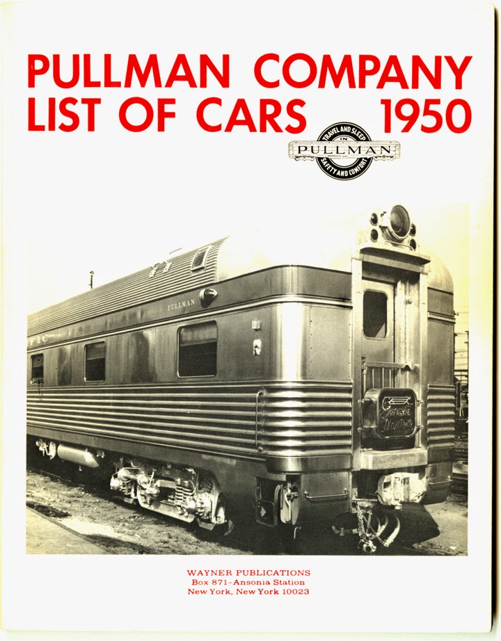
     Back in the 1980s, when I started to put together some heavyweight sleepers, the best available model in HO scale was the Rivarossi (later AHM) car. It models a 12-1, that is, a 12-section, 1-drawing room car, by far the most common single floor plan in the Pullman fleet (about half of Pullman’s 9000 cars were 12-1 cars), and thus a good choice by Rivarossi. In those days, long before the SPH&TS had published its magisterial volumes on the SP passenger car fleet, one relied on one of Bob Wayner’s books, a reproduction of the Pullman Company List of Cars, 1950. Here you can look up car names (or numbers) and find out what kind of car it was, and to whom it was sold in the breakup of the Pullman fleet in 1948.


     Using this book, I quickly found a couple of names of SP 12-1 cars I liked, and repainted and lettered a couple of Rivarossi model cars accordingly. The easiest modeling pathway is to ignore the fact that most of these car were air-conditioned by 1953 and just do a repaint, which is how I made the Tuolumne. (You can click on the image to enlarge.)


     But as I say, in reality the great majority of these cars had air conditioning, meaning pretty darn visible rooftop ducts. (Air conditioning dates for SP cars are available in the SPH&TS series, Southern Pacific Passenger Cars, Volume 2 on sleeping cars.) I made these ducts the hard way, starting with wood shapes from Walthers, then working many, many layers of modeling putty to get the contours to blend smoothly. That makes my model of Inyo a bit more realistic than Tuolumne. This model shows the common arrangement, in which ducts did not extend over restrooms or aisleways.


Next I wanted to do one of these cars in Two-Tone Gray, though in 1953 that was not yet a standard scheme for pool cars. It was certainly in use on relief cars for particular trains, which is how I chose to regard Serra (at that time having no source of information of the dates of paint schemes on individual cars; see the SPH&TS series). The only modeling complication is that white lettering is needed.


     My last 12-1 model was to capture the fact that sometimes cars from the Northwest railroads with which SP connected in Portland, NP and GN, traveled beyond their normal southward limit, the Bay Area, and reached Los Angeles. They would then return northward. I chose to model a GN Pullman with the name Columbia Glacier.


This is not an actual Pullman name, but is similar to the names of a number of Great Northern Pullmans, for example Harrison Glacier, Grinnell Glacier, Blackfoot Glacier, and Sexton Glacier. (Those cars were a series of duplex-bedroom cars.) The Pullman Company did have a “Columbia” series of 10-section observation cars, but not a Columbia Glacier in that series. Given that there is a real Columbia Glacier in the North Cascades of Washington State, and it is part of the headwaters of the Skykomish River there, it seemed like a good choice of name for a GN car.
     But I really wanted to go farther than the 12-1. Yes, the SP owned and operated a fair number of 12-1 sleepers, but SP really seems to have preferred other types, usually cars with more room accommodations, such as the 10-1-2 (10 sections, 1 drawing room, 2 compartments), the second-most numerous floor plan after 12-1, and I wanted to see if I could model some of them, too. That will be the subject of the following post.
Tony Thompson

Friday, July 11, 2014

Constructing Santa Rosalia — the water’s edge

In my previous post about the town of Santa Rosalia, located at the end of my mythical Southern Pacific branch line, I described how far I have gotten to date with painting the backdrop for this section (you can read that post at: http://modelingthesp.blogspot.com/2014/01/constructing-santa-rosalia-backdrop_29.html ). I envision Santa Rosalia located at the mouth of the Santa Maria River, just at the Pacific Ocean shore; see my earlier post at: http://modelingthesp.blogspot.com/2011/01/layout-design-locale.html .
     With that location, Santa Rosalia can have a modest waterfront, and should be able to serve as a home port for fishing boats. [I will discuss the Central California fishery and its boats in a future post.] Before I went to the next step and began arranging track for this part of the layout, then, I needed to identify where I would place a waterfront scene. This post takes up that subject.
     As is probably evident from photos of this part of the layout, I really don’t have enough space to model very much seafront or piers of any size, so I decided to settle for a modest wharf. Anyone setting out to do this ought to look over John Pryke’s fine article in the September 1997 issue of Model Railroader, pages 60–65, as he presents a number of nicely worked-out details you can add. Pryke did another nice article on waterfronts in the Model Railroader issue for February 2010, or see the  series in Model Railroader from last year, on their “Rice Harbor” layout, especially the March 2013 issue with an article on building the harbor. My main difference with these articles is in the method of making water, about which, more in a moment.
     I decided that a seawall would be an adequate way of depicting the shoreline near my future fish cannery. As it happens, Frenchman River Model Works makes a nice set of cast resin parts (part no. 1573) which are rows of pilings, one way to make a seawall. I reasoned that if I added details like bollards or bitts or cleats along the edge, I could tie up a model boat to this seawall. And Frenchman River offers detail parts of all those mooring devices, so I ordered a selection of them.
     Here is how the Frenchman River seawall parts look in the package. Each of the three sections is five inches long and about 1-1/8–inch high, a little taller than fits my situation, but if need be they can be cut down.


The molded brown color is too light and too brown for realistic pilings, but this is easily changed, and is an excellent base color.
     I approximated the size of the area I wanted to model as water, and cut the Homasote in that area accordingly. This is in the back corner of the Santa Rosalia extension structure. I only sought to have enough water to include a tied-up fishing boat [I will return to the boat in a later post], so this is not an extensive marine scene. I also added a raised walkway along the edge of the seawall, as is often seen.
     This photo shows the corner where the water will be (the exposed plywood, at this stage). It is the far corner of Santa Rosalia, visible in the second photo of the post cited ate the top of this post. At this stage, the walkway is just Homasote strips.


The next step was to prepare the area for the water coating. I like to make a small-radius cove along the edges where the backdrop meets the horizontal surface, so that the corner is not obvious.
     My usual method of making model water does not use clear casting resin. Aside from the complications and mess of placing the resin, I have noticed on the layouts of others, that over time that the resin surface becomes dull and cannot really be cleaned. I long ago decided to represent water some other way.
     In my ocean beach scene, I painted the color of the water, then used gloss medium as a top coat, which dries clear and nicely glossy (you can read about it at this link: http://modelingthesp.blogspot.com/2013/11/rebuilding-my-ocean-beach.html ). Not only does it seem to clean well with a damp sponge, it can readily be re-coated with more gloss medium if needed. I’ve been very happy with my ocean water in that beach scene, and will use the same method here at Santa Rosalia.
Tony Thompson