Reference pages

Tuesday, August 31, 2021

Cars on the layout for an op session

Not long ago, I received an interesting question about operating (or op) sessions via email. The questioner didn’t want to be identified, so shall remain anonymous, but I thought it might be useful to explore the topic that was raised. And that topic was, selection of freight cars to populate the layout during op sessions (implied, of course, is that the layout owner has far more freight cars than can be on the layout at any one time, certainly a description that applies to me). 

I have discussed several times how I set up the layout for operating sessions, including some description of car selection (see, for example, the post at this link: https://modelingthesp.blogspot.com/2021/07/selecting-cars-for-op-session.html ). But the questioner wasn’t so interested in setting up, just in car choices. So here’s an overview.

I always start with home-road cars. My layout models the Southern Pacific, so of course the SP’s cars will be very visible. However, I’m aware of several studies of SP yards and trains (and a few conductor’s books), all of which show home-road cars to be around 25 to 35 percent (for example, see the analysis here: https://modelingthesp.blogspot.com/2011/03/modeling-freight-traffic-coast-line_11.html ). So I keep that in mind in considering whether there are too many or too few SP cars present.

A related point is that Pacific Fruit Express, owned equally by Southern Pacific and Union Pacific, would be the supplier of most empty refrigerator cars spotted for loading. The exception would be in peak harvest season (August to October), when up to a fourth of all empties loaded would be borrowed cars from other owners, heavily ART and BAR, but also others such as MDT or the FGE family (meaning FGEX plus WFEX and BREX).

Second, I believe that the cars of the largest freight railroads will always have a presence, if not in one particular session, certainly in the next. In the top five for size, along with SP, were the Pennsylvania, New York Central, Santa Fe and Milwaukee Road. 

It’s well-known that the SP and the Santa Fe were fierce competitors in much of SP’s territory, and further it’s known that both railroads tried very hard never to spot the competitor’s empty freight car for loading on their own lines. 

But of course inbound loads from elsewhere in the country could quite likely arrive on either road in the competitor’s car. So the only special point to recognize is that when those cars were made empty, they were returned directly to the owner, almost never spotted for local loading. But they will certainly be present.

Next is a list of the remaining “top 15” railroads.  I repeat below the graph for 1950 that I have shown previously in several places, showing the size of car fleets, minus coal and ore hoppers. (For a defense of the adjustment, see this: https://modelingthesp.blogspot.com/2021/05/proportions-of-freight-car-fleet.html , or my article in Model Railroad Hobbyist for  December 2011).

You can readily see the railroad names to the right of the Milwaukee, which are my other “try to include” reporting marks in any session. Although Gilbert-Nelson suggests that much traffic is just in proportion to the graph bars you see above, I still tend to use MP, CNW, CB&Q, UP and NP above most of those roads. 

A further point is that Western railroads in the early 1950s, whether or not they served any grain-growing regions, had significantly higher percentages of box cars than the national average. Accordingly, the cars you are most likely to see on my layout from the Western roads are going to be box cars.

Fourth, I make an effort to include smaller railroads, ones that don’t appear in the graph above, like Western Pacific, D&RGW, DT&I, Central of Georgia, or B&M. And of course I try to include an occasional car from the “residue” little railroads or little car fleets, as I described recently (consult this post: https://modelingthesp.blogspot.com/2021/05/the-unusual-cars-on-your-freight-roster.html ). 

So when you see a scene like the one below, with a bunch of cars in the yard at Shumala on my layout, it is no coincidence that you see a B&O car, along with a New York Central flat car and a UP box car. Cars from the major railroads are present on purpose.

And at the same time, most sessions will include a car from a small or a very small railroad. An example is shown below, from a recent operating session, during switching in my layout town of Ballard. Spotted on the house track is a car from Minneapolis, Northfield & Southern (MNS), a railroad that only had a 100-car fleet: all PS-1 box cars, built in 1952, like the one shown here.

I should also mention that in the foreground, spotted at Guadalupe Fruit’s loading platform, is a car from the Lompoc & Cuyama short line (for more on the latter, see this post: https://modelingthesp.blogspot.com/2012/03/survival-from-my-old-layout.html ). Cars from the L&C show up very rarely on the layout.

My points here are that I do have a scheduling system, and I do call on waybill sequences for some of the car choices for operating sessions. But I also make sure that other criteria for representing railroads are fulfilled. I can and do juggle whatever the “scheduling” throws up. I think my position on this is that any layout contains an awfully small sample of freight cars, and can easily represent a pretty unusual lineup of cars; but I would like to have sessions appear more “typical”of averages, so make changes to suit.

Tony Thompson

Saturday, August 28, 2021

Waybills, Part 88: temporary waybills

 Ordinarily, a loaded freight car ready for pickup by a switch crew would have its full waybill ready to go with it, typed by the agent. In fact, the waybill was required for pickup — usually. But on some occasions, a hot shipment might need to move immediately, while the waybill was held up for some reason. 

Most railroads dealt with this situation by having a particular form, called a “loaded car card” (example below) or “interim bill” or “temporary car slip” or something similar, so that the car could begin its journey. The waybill might then be prepared the following morning, and would catch up later. 

A second reason why a waybill might not be available immediately is if the shipper were located at a station with no agent on duty. The temporary waybill then allows the conductor to pick up that car. The Bill of Lading then must be transmitted to a station with an agent for waybill preparation, likely a nearby station.

Below is an example from the Northern Pacific, and it is 9 inches tall and 4 inches wide: just what will comfortably fit in a stack of 8.5 x 11-inch waybills folded in half the long way. This original form was given to me by Gary Wildung, and I have briefly described it previously (see the post at this link: https://modelingthesp.blogspot.com/2015/12/waybills-part-46-more-car-slips.html ).

Use of such bills was certainly intended not to be frequent. Among the indications of that are the instructions printed right on the card, suggesting that conductors might not be familiar with this procedure. Let’s look more closely at them (I also showed these instructions in the post cited above). 

In the full card, above, there are nine instructions. For our purposes, there are really four important ones, shown below. They are largely self-explanatory. You can click on the image to enlarge it if you wish.

Note a couple of things in particular. First of all, the second instruction makes clear that this is an on-line bill only. It cannot served beyond the rails of the issuing road, just like an Empty Car Bill. And secondly, the idea is for the full and complete regular waybill to be sent by passenger train, to catch up with the loaded car at or before it reaches the destination point filled out on the slip.

In the very interesting volume, The Station Agent’s Blue Book (by O.D. Kirkpatrick, Kirkpatrick Publishing, Chicago, 1928), this kind of document is called a “Card Waybill,” in the chapter entitled “The Freight Waybill.” Little is said about it, however, and perhaps in that era it was not much used. 

But as already noted, the NP example above, dated 1950, clearly explains the usage, and Southern Pacific’s Circular 39-1, “Instructions to Station Agents,” contains extensive coverage of such waybills.

[Incidentally, I might mention that I posted a series of what I found to be quite informative descriptions of SP practices, taken from the “Instructions to Station Agents.” You can use that title as the search term in the search box at the top right of the first page in the present post. But none of those five posts were about these particular waybills.]

Southern Pacific called these waybills “conductor’s memorandum waybills,” which were standardized as Form 704. (My previous posts from Circular 39-1 mentioned several different waybills with 700-series numbers.) Directions for the use of Form 704 make clear that it was used in nearly exactly the same way as the NP form shown above. 

The directions in Circular 39-1 for using form 704 waybills are contained in rules 1103 to 1117, most of the rules dealing with details of accounting. But here are the main directions of interest, which you will note are quite similar to those of the NP form above (again, click to enlarge). 

The emphasis in the text above is on “non-agency” stations, meaning stations at which no agent is on duty.  Obviously with no agent available, there would be no one to prepare a waybill. But some other comments in the Circular 39-1 rules suggest, exactly as with the NP document, that for any situation where waiting for a waybill would delay a shipment, Form 704 was to be used.

How might we implement such a waybill slip on model layouts? I would like to have one so that it can be used just occasionally, perhaps in peak perishable shipping season, or some other kind of vitally-needed load. Obviously we can begin with the NP card — I would use an SP version if I had one — and see how it can be adapted and simplified. I have been experimenting in this direction, and will take up a description of all that in a future post. 

Tony Thompson


Wednesday, August 25, 2021

Family still operating

 The fact that there continue to be semi-formal operating sessions on my layout, involving my granddaughter as engineer, isn’t really of great importance in the scheme of things, except that as we experience a fourth surge of the pandemic, many people are again becoming hesitant to enjoy social events like operating. So in that way, I guess it does matter that we are managing to operate the layout.

As usual, she prefers to be the engineer, and has quite a good touch with the NCE throttles that are my layout’s system. She is intrigued by waybills but doesn’t entirely grasp how to organize them to carry out a session. Sometimes her grandmother serves as conductor, but the last two sessions, we have tried something different for her to prepare. First, I stage the layout, and then she and I survey the layout area to be switched, making up a switch list. In this way, she sees the planning as well as beginning to scope out the work that will be done.

For our session the other day, the area to be worked was Shumala. Below you see her operating the diesel switcher in a runaround move at the west end of town.

Runaround moves are needed at Shumala for the switching moves that are essentially facing-point in character. In this case, she is preparing to switch at East Shumala.

There are also facing-point moves in Shumala itself, in the industrial tracks at the rear of that layout area. In the photo below, taken over the head of the young engineer, you can see the diesel switcher setting out a car at Associated Oil. Next to the engine is a second tank car, which will replace the empty car seen above the turntable, at the Southern Pacific fuel spot.

Then the switcher returns with the two empty tank cars picked up in the moves just shown. Here it’s backing past the yard office with the empties.

Eventually all the facing-point moves are completed, and then the session can finish up with some much more convenient trailing-point moves. Below you see an empty SPMW reefer, about to be spotted at the ice house to pick up an ice cargo, that will be distributed to section crews. This reefer, by the way, was described some years ago as part of a series about modeling SPMW cars (see that post at: https://modelingthesp.blogspot.com/2013/04/modeling-some-sp-mow-cars-part-2.html ).

Finally, the session is almost done. Just one job remains, to spot the caboose that you see standing on the branchline main, over to the caboose service track. (It arrived with the last returning Santa Rosalia Local.) The switcher, located near the lower left corner of the photo, is about to go and do that task. All the other cars you see in the yard are the various loaded and empty pickups from the session just concluding. 

This was (deliberately) a fairly full session. We picked up or set out about 20 cars, more than I would schedule for most crews in an adult operating session at Shumala, so this was a fair amount of work. But the engineer enjoyed it all. Whether she is interested in modeling as such is less clear, but she does like to run an engine.

Tony Thompson

Sunday, August 22, 2021

Western Maryland hoppers, Part 2

 In introducing this topic, I showed some prototype photos to illustrate a few of the reasons that many modelers and railfans fell in love with the Western Maryland. I also showed models of the two major and distinctive classes of WM hopper cars, the channel-side and the drop-side designs. That post can be found here: https://modelingthesp.blogspot.com/2021/08/western-maryland-hopper-cars.html

[I should have mentioned, and apologize for forgetting, the superb book by Bob Karig, Coal Cars (Univ. of Scranton Press, 2007). This book contains a phenomenal amount of information about hoppers, from history to design and construction, and to service history. It also includes a very large gallery of car photos. If you have even a faint interest in hoppers, find yourself a copy of this book.]

When starting to draft that first post (see first paragraph, above), a very faint bell rang in my memory. I had a feeling that I owned another drop-side hopper model, somewhere. Since such a car was not in my active inventory, I opened up my “storage” box of old or discarded or unworkable models. Sure enough, there it was, a nicely assembled Ulrich hopper car that I had picked up at a swap meet.

You can see it’s lettered for the Big Four (Cleveland, Cincinnati, Chicago & St. Louis, or CCC&StL), formed in 1889 as a component of the New York Central. However, to my knowledge the NYC System never had any, or had any significant number, of the drop-side design hoppers. The number on the model, 79325, in fact lies within a group of 1918-built USRA hoppers on the CCC&StL, which were cars with straight side sills.

Although the model is nicely lettered, the lettering style is that of the 1920s (though some examples may have survived into the late 1940s), and I already have NYC System hoppers. The thought promptly surfaced that I could repaint and reletter the model as a WM car. 

(Incidentally, back in the 1950s, Ulrich offered this car body in a variety of road names, as you can see in the 1959 catalog segment below, including Western Maryland. They even lettered the car for Pennsylvania, though the body style is not exactly PRR. You may find any or all of these road names on Ulrich hoppers for sale on eBay.)

Before repainting, I removed the glued-in load, so I could make it removable. I added the missing brake wheel, and wire for the left-edge hand grab, and painted the model with Tamiya’s “Oxide Red” Fine Surface Primer, which is an appropriately rich red-brown.

Next came lettering. The issue here is which and how much lettering to apply. As built, the cars had much more lettering than when repainted. To demonstrate, below is a Bethlehem builder photo, provided to me by the late Larry Kline. This is 1942 lettering.

Incidentally, note the lettering here, between the hopper outlets, showing that the car has a Duryea cushion underframe (you can click on the image to enlarge it if you wish). I made no attempt to model this underframe, or lettering about it. I also omitted most other lettering on the right side of the car, because it was omitted in later years, as you can see in the photo below (Internet image, uncredited).

I used parts of the old Champ HN-60 set, the most valuable part of which may be the correct size railroad herald to fit the rib spacing. Most of the remainder is from the both Champ and Sunshine decal capacity data.  I lettered my car within the 10000–14400 number series of this large group of twin hoppers. Here is the model, awaiting weathering. Addition of reweigh and repacking stencils will follow weathering (I will letter the reweigh for Elkins, symbol EK, where there was a car shop).

Even if, as a California modeler, I really need awfully few hopper cars on my layout, I still find them to be interesting prototypes and models. The present post is just one expression of this. For another example, you may consult this post: https://modelingthesp.blogspot.com/2019/04/panel-side-hopper-car-part-2.html .

Tony Thompson

Thursday, August 19, 2021

Full-width diaphragms, Part 3

 This is the third post in this series about the full-width diaphragms that were adopted by a number of railroads including Southern Pacific, for new cars in the early days of streamlined lightweight passenger trains. In the first post, I described and illustrated the prototype, with several photos to illustrate the features of these interesting appliances. You can see that post here: https://modelingthesp.blogspot.com/2021/07/the-challenge-of-full-width-diaphragms.html

In the second post, I made a few observations about commercial products that can represent the full-width prototype diaphragm, either in flexible, working form or in a rigid plastic form that does capture the appearance, though not all aspects of the operation. Here is a link to that second post: https://modelingthesp.blogspot.com/2021/08/full-width-diaphragms-part-2.html .

Now I want to turn to face plates for these diaphragms, particularly the distinctive shape of many of the ones used by SP. These have sometimes been called “opera window” plates because of the peekaboo openings at the top (possibly to save weight). Below is a repeat from the first post, a clear photo of such a face plate on a 1947-built SP car.

One way to make model versions of these plates is simply to cut them from styrene, after making a pattern. I made patterns by taking a photo like the one above, increasing the contrast using Photoshop, and then sizing the height of the plate in the photo to 9.5 feet in HO scale (about 1-5/16 inch). Here’s the relevant part of the photo above.

Next I printed out this image on ordinary paper, cut it out with a hobby knife, and then transferred the outline with a pencil to 0.010-inch styrene sheet. Shown below are a paper pattern, cut from the printed-out photo above, and a “first-cut” styrene piece, obviously needing refinement, but I want to show it at this stage to show you don’t have to get it perfect at the start. 

The starting blank at right has too high a curvature at the top, and the upper holes are too small and poorly shaped. But with the thin styrene sheet, these defects are quickly corrected with small round and flat files.

Shown below is the same “blank” shown above, but refined in shape and primed with a medium gray color, prior to preparing for use on a model car. This still needs rust tones added.

This will be attached with canopy glue to a full-width diaphragm, or to a residual “narrow” remnant diaphragm. By the latter, I mean what remained after the removal of the full-width part of the diaphragm. The photo below shows such a diaphragm and face plate, on a single-unit diner, SP 10200 in 1956 (Doug Richter photo). You can click on the image to enlarge it if you wish.

I have made a number of these “opera window” face plates, for use on full-width or remnant diaphragms for appropriate cars. I will go into their application in a future post. 

Tony Thompson

Monday, August 16, 2021

A C&BT Shops box car, Part 2

 Last spring, I showed the model work behind re-detailing a box car from C&BT Shops. The idea was to take advantage of an excellent car body molding, and eliminate the unfortunately sub-par detail parts supplied in the C&BT Shops kit. I showed all my changes. You can read that post here: https://modelingthesp.blogspot.com/2021/04/redetailing-c-shops-box-car.html .

Next came a choice of prototype for which to letter the car. The C&BT Shops model is a post-WW II box car, with an early Improved Dreadnaught end and a straight-panel roof, placing it in the range of built dates between 1944 and 1949. It also has the then-common 6-foot corrugated door. I decided to use it as a stand-in for cars of that general ancestry.

My goal was to fulfill the description I offered in a previous post, that even though small or unusual railroads might singly be all but invisible in the national car fleet, collectively they do add up to something more significant. That means we should have some such cars, whatever they are. I laid out that argument in this post: https://modelingthesp.blogspot.com/2021/05/the-unusual-cars-on-your-freight-roster.html .

For this car’s prototype, I chose the Atlantic and Danville Railway, an east-west railroad across the southern edge of Virginia, from their headquarters at Norfolk to Danville, with about 200 miles of line. The choice was partly because a friend had told me that K4 Decals had a nice set for this railroad. (You can see their extensive line of decals here: https://k4decals.com/ .)

For more about the railroad, I show below the A&D Railway page from the Official Guide of the Railways, issue for January 1953. You can see immediately that the railway actually had a quite accurate name: from the Atlantic to Danville. I show the entire page, page 559, only so that you see the emblem in the lower right corner.

This page illustrates a further point I will make in passing. The Official Guide can give you information about smaller railroads that you will not readily find anywhere else. These books were at one time monthly and were published in very large print runs, so they can usually be purchased from on-line and other sellers. And as the above example shows, they are definitely not only about passenger schedules, though many railfans and modelers perceive them that way.

I can illustrate the paint scheme as shown on the photo below (photo courtesy Jim Seagrave). This is a much older car than the C&BT Shops model, having been built in 1927, but it clearly illustrates what I want to show.  And note the reweigh date, which is February 1956. I don’t know the age of the paint scheme, but this is the same emblem you see in the A&D page from the Official Guide, above.

I used K4 set ADB for this, which is intended for the 2200-series cars, though I am confident that they were not yet on the railroad in my modeling year of 1953. So I chose a 2100-series number, even though it’s not the right body. Yep, it’s a stand-in, acceptable to me in part because it’s not a well-known railroad.

These K4 decals are nicely printed and go on well. I recommend them. I did need to add a reweigh date, but otherwise what you see below is the decal set as provided, with an overcoat of flat finish. The model still rests on its “interim truck support blocks.” (These support blocks were described in an earlier post, at: http://modelingthesp.blogspot.com/2014/11/interim-truck-support-blocks.html .)

Completing the car will only require some weathering, which is not important to the present narrative. This car will definitely fulfill its role on my layout as a member of the “unusual railroad” car fleet, individually insignificant but collectively visible. Of course, like other “fun” categories of rolling stock, this one does require self-control.

Tony Thompson

Friday, August 13, 2021

Heavyweight sleepers again, Part 2

 In the previous post, I reviewed the Thomas Hoff method of cutting out and replacing window and wall sections of model Pullman sleepers from Rivarossi (sold by AHM, Associated Hobby Manufacturers). That simple method was thoroughly described in five articles in Mainline Modeler in 1981, and in the “Best of Mainline Modeler” book I showed in the previous post (it is here: https://modelingthesp.blogspot.com/2021/05/modeling-heavyweight-sleepers-again.html ). That post also showed the first steps on the present model.

One thing to do before painting the modified Pullman I’m building, inside and out, is to add partitions around the room accommodations and the restrooms. Rivarossi did produce a molded plastic Pullman interior, and it can readily be kitbashed for floor plans other than the original 12-1 (12 section, 1 drawing room), as I showed in a post awhile back (you can find it at this link: https://modelingthesp.blogspot.com/2014/08/modeling-sp-passenger-cars-pt-4-sleeper.html ). These interiors are usually available for sale on the Internet, as “AHM 1920s Pullman interior.”

But for Pullmans in deadhead moves, where no passengers would be on board, which is a common Pullman move on my layout, the interior seats (barely visible anyway) and passengers can be omitted. The only thing really needed inside, then, are the partitions mentioned above. I used 0.030-inch Evergreen styrene sheet for these. I also used some 1/8-inch square styrene strip for the inside corners of these partitions. These corner strips are effectively invisible in the car interior.

These partitions are shown below (they might better be described as “view blocks,” since there are some areas of the car where one should not be able to see clear through the car). The larger one is for the end of the car with room accommodations, divided for the women’s room at the end. The smaller one is for the men’s room at the other end. Do check clearances of these partitions before proceeding further!

Next I spray painted the entire car interior, and both sides of the partitions. I chose a Model Master color called “Light Ivory.” Pullman used a variety of interior color schemes, all of which used very muted colors. If anything, the Ivory is probably too light, but for visibility through the car windows, I thought it would help make visible the fact that there is some interior. In the photo below, partitions are loosely in place, not yet glued.

With the interior painted and thoroughly dry, I ran a strip of masking tape along the entire interior of the car. This ensures that the sides of window openings will be body color, but that the interior color is maintained. (And the interior partitions were removed for this step.)

I then airbrushed the outside of the model with Star Brand “SP/UP/D&RGW Dark Olive,” STR-29. This paint is an excellent match to the SP Common Standard drift card for Dark Olive Green. And it goes on smoothly and does not affect the bare plastic model surfaces. But because the body molding is black plastic, several thin coats should be applied to ensure that the color is fully developed. The Dark Olive car is shown  below, merely resting on the trucks, not with them installed.

The use of SP Dark Olive Green instead of Pullman green is deliberate. Pullman green would be the correct color, but that prototype color is very dark. Under indoor lighting, as on a model layout, it really looks too dark. For years I used to lighten Floquil’s Pullman Green with some of their Coach Green, but I now feel that Dark Olive Green is a better choice.

Next comes the issue of how to letter the car.  As mentioned in the previous post (link provided in the first paragraph of the present post, above), this model is intended to approximate a Pullman 10-1-1, which means 10 sections, 1 compartment, 1 drawing room. Since Southern Pacific only bought two cars of this floor plan from Pullman, I decided to model the car as one that remained in Pullman ownership (and lettering) after the 1948 sale of much of Pullman’s fleet to the railroads. 

You can find a clear and factual account of the Pullman sale, and the SP role in it, in the very informative volume, Southern Pacific Passenger Cars, Vol. 2, “Sleepers and Baggage-Dorms” (SPH&TS, Pasadena, 2005). This is described in the book’s Chapter 3, pages 165–217. Because my model is not quite an accurate 10-1-1 nor a 10-1-2, I realized that I needed to use a name for the car from one of Pullman’s car name groups that was applied to multiple car types.

(For Pullman name and railroad-sale destinations, I rely on Bob Wayner’s book, Pullman Company List of Cars, 1950, Wayner Publications, New York, 1985. For previous examples of using this book, you may consult my post at: https://modelingthesp.blogspot.com/2018/02/my-pullman-projects-part-2.html .)

I chose the “Lake” series, of which there were several. Moreover, rather than conflict with the history of an actual car purchased by SP, I decided to use a different Pullman name. I chose a name that might well have graced a Pullman in SP service, Lake Merritt, named for the prominent lake in Oakland. I chose the excellent Thin Film decal sheet, HO 160, which readily provided all I needed. (You can click on the image to enlarge if you wish.)

I still have to rebuild the car roof to include air conditioning ducts, and to manage a few more of the car details. I will turn to those tasks in a future post.

Tony Thompson

Tuesday, August 10, 2021

Electrical wars, Part 18

This is another one of those posts with a series number, clearly showing that it relates to an ongoing experience. In this series, it refers to electrical problems on the layout. I don’t mean to imply that these are of such severity that the term “wars” is really appropriate, though sometimes it does seem that way. Maintenance is just what comes with advancing age of layouts, especially if they are “exercised” fairly regularly (by which I mean “used for operating sessions”). 

(Incidentally, if you would like to seek out prior posts in this series, the simplest way is to use “electrical wars” as the search term in the search box at right.)

The problems I describe today are examples of those intensely annoying ones, that are intermittent. It is, of course, much easier to track down consistent problems. The first of these was a track that sometimes lost power, in ways that did not seem at all obvious, let alone consistent. I am still not certain of all the reasons that may have contributed, but perhaps the solution will be interesting to readers, because I had to do three separate things.

First, I notice that one of the necessary electrical gaps did not seem to be very open. I have talked about this kind of problem before (see my post at this link: https://modelingthesp.blogspot.com/2018/10/electrical-wars-part-16.html ). That post, and my current work, involved making sure there was a gap all the way through the rail (sometimes a cut-off disk doesn’t quite cut the rail foot entirely).

The solution, of course, is to make sure it’s fully open, and then put a little slab of styrene in it, usually glued in place with canopy glue (though CA works fine too). You can see that below. The uppermost rail in the photo has its white styrene gap filler a little to the left of the photo center, and the rail below it in this view has its gap about two ties to the left of that. These will of course be painted so their white color doesn’t stand out.

But that was only insurance for a doubtful gap. I also had to check all the feeders to the track that had intermittent power, and found a wire loose and partly broken at a terminal strip under the layout. That was an easy fix, of course; re-strip the wire end and re-attach to the terminal strip. 

But that fix only helped part of the problem. I eventually realized that I was also experiencing intermittent operation of a Frog Juicer, not powering the Peco switch whose frog you see above, but for the turnout just to the right of the switch in the photo above.

Let me hasten to say that the Frog Juicer, made by Tam Valley Depot, is a superb product, and has for some years now, performed flawlessly for me on a number of switches on my layout. To date, I have only used the Mono Frog Juicer models, that is, a device to operate single switches (see a description of their product line, and considerable informative material, at their web site: https://www.tamvalleydepot.com/products/dccfrogjuicers.html .) 

But this particular Juicer, after years of service, did need to be repaired. The folks at Tam Valley Depot did the repair. With the above maintenance actions, and the repaired Juicer, all the track in that area worked perfectly. 

As an illustration, below you see the switcher that’s stationed at Shumala, spotting a flat car at the East Shumala team track (the crates were described in a previous post; see it at: https://modelingthesp.blogspot.com/2021/06/open-car-loads-crates-part-4.html ). The locomotive has just traversed the former problem area.

Meanwhile, the other problem was over at the switch in Shumala leading off the main line into the (railroad) east end of the siding. There I encountered another case of erratic operation of a Frog Juicer. But in this case it was due to two (presumably) independent problems. 

One problem was a separated bond wire from a stock rail to a point rail, easily re-soldered. The other was some kind of electrical leakage that had developed in the gaps at the frog. See below. This was discovered using a multi-meter.

You can see above that I did a poor job rebuilding this Shinohara switch for the Frog Juicer, because the cuts in the point rails, where they are  hinged with rail joiners to the frog rails, are awfully close to the electrical gaps in those frog rails (just to the right in the photo above — the upper one has white styrene freshly replaced in it). 

I avoided this mistake in subsequent rebuilds of other switches. But once I had cleaned and verified the two gaps shown above, and soldered that bond rail, all was well. The Frog Juicer worked perfectly, as it always had previously. Both these problems are in trackage that has been in use for years, and has been part of dozens of operating sessions, without problems. Now they develop. Sigh.

I am once again reminded of Jim Providenza’s advice on layout maintenance: “Trust nothing. Check everything.” Excellent advice, as always. And by applying that advice, I fixed both the problems described above. Back to operating!

Tony Thompson

Saturday, August 7, 2021

Western Maryland hopper cars

 West Coast modelers like me have minimal needs for hopper cars, at least for carrying coal. There certainly was some traffic of that kind, as I showed in a post awhile back, but not a great deal of it. (That post can be seen here: https://modelingthesp.blogspot.com/2018/02/coal-in-california.html .) And in fact, I had written more about that topic in an earlier post about coal traffic, and here is that link also: https://modelingthesp.blogspot.com/2016/06/coal-traffic-on-my-layout.html . This latter post in particular goes into the reasons that eastern coal hoppers may appear on my layout.

One can of course choose whatever eastern coal roads one wishes, but in fact some coal roads had far more off-line traffic than others, generally through brokers, compared to the roads whose coal traffic was heavily slanted to export coal piers. One of the roads with significant off-line traffic was the Western Maryland. 

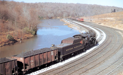
Now in one sense, the WM was just another small railroad, but to many, it was a railroad that stood out beyond its size. One reason in steam days was the pride of WM employees, revealed in so many ways, perhaps most visibly in the clean locomotives and tenders. Roundhouse employees wiped down engine jackets and tenders with kerosene between runs. 

Innumerable photos show this appearance, though the WM was a hard-working railroad hauling mostly coal. I show just a single example below, one of a great many superb Bill Price photos from his book, Western Maryland Steam Album (published by the Potomac chapter, NRHS, 1985).

This photo shows Class H9 Consolidation 821 at Thomas, West Virginia,  in the fall of 1953 (BTW, these were big locomotives). Who would expect gold striping and a color emblem (called a “fireball”) on steam tenders, and invariably kept clean like this? Note also the distinctive WM channel-side hoppers behind the engine.

Years ago, I wanted to model one of these channel-side hoppers, representing some 1500 cars that had 7 channel-section side posts. They were built new this way by Bethlehem Steel in 1927. As it happened, I wrote a piece about my model for Model Railroader’s then-monthly column, called “Paint Shop,” conducted by Jim Hediger, in the June 1983 issue, on page 122. Here’s a photo of my model.

The model is an Athearn “blue box” twin hopper, with ribs carved and sanded off and replaced with Plastruct channel. I also replaced the brake wheel and trucks. I used Champ’s HN-60 WM decal set, and weathered the car, especially the interior. The Athearn body is a little larger than the WM prototype but has close to the same proportions, so looks all right in use.

The other distinctive WM hoppers were often called “drop side” cars, with side sheets extending below the side sill. Cars of this design were not widely owned — the Lehigh Valley, Atlantic Coast Line, and the Reading had some, and the N&W had a lot — but they do stand out on the WM, totalling 4400 cars. That’s a lot on a 13,000-car railroad. Bethlehem Steel built these cars for the WM and the LV. (I should emphasize that the enormous majority of hopper cars in North America had straight side sills.) Here’s an example of the WM drop-side car.

This photo is by Robert Collins, showing a mid-train helper, Class I-2 Decapod 1124, on the Mount Savage grade near Frostburg, Maryland. Note that a channel-side car is visible here also, thus showing both kinds of distinctive 7-rib WM hoppers. Incidentally, this photo is from a book with the wonderful title, The Western Maryland Railway: Fireballs and Black Diamonds, by Roger Cook and Karl Zimmerman, Howell-North, 1981.

Stewart Hobbies years ago produced a styrene model of this drop-side hopper, and I had one in my stash. I decided I should assemble it to keep my channel-side car company. It does have separate ladders, helping the appearance, and I replaced the brake wheel and the wheelsets, while installing Kadee #158 couplers in the kit boxes. It of course needs weathering, which will be applied in an upcoming session for multiple cars from the “paint shop.”

And there is one other point to  make, in addition to the distinctive WM locomotive appearance in its heyday. That would be my own experience, when I lived in Pittsburgh, visiting former WM sites like Elkins, West Virginia, during Chessie days (and talking to employees, who would immediately tell you if they had started on the WM). That very much makes it fun to model a bit of the WM. So when I enjoy occasionally spotting a car of eastern “met” coal (metallurgical) at my Jupiter Pump & Compressor industry, it’s especially nice that these two WM hoppers can be among them. But this isn’t the end of the story. More to come.

Tony Thompson

Wednesday, August 4, 2021

Full-width diaphragms, Part 2

 The full-width diaphragms adopted by Southern Pacific (and other railroads) for lightweight streamlined equipment present a modeling challenge in any scale. Not only are our model curves and switches far more sharply curved than the prototype, our car separations are much larger than prototype (the two problems are connected, of course). I introduced this topic in a previous post (see it at: https://modelingthesp.blogspot.com/2021/07/the-challenge-of-full-width-diaphragms.html ).

In this post I discuss various commercial diaphragm products that can serve on our model passenger cars. Two of them are shown below, on the left the Broadway Limited working Daylight diaphragms, the same as the ones on their ready-to-run Daylight cars. On the right is a package of the American Limited styrene versions of the same diaphragm, which although not operating in the same sense as the rubber-sheet ones, does provide some relative motion of an inner and an outer frame.

Incidentally, the Broadway Limited package costs about five times as much as the American Limited package; each will do one car. The BLI diaphragms are already decorated for the Daylight, while the AL parts are unpainted. I should mention that Coach Yard has intermittently offered working diaphragms also.

I assembled the pair of American Limited diaphragms shown in the photo above. These comprise the same core pieces (an “outer bellows” and an “inner bellows”) as their regular “Pullman” diaphragms that I have shown before (you can find that post at: https://modelingthesp.blogspot.com/2021/07/passenger-car-diaphragms-part-4.html ), and the core pieces are assembled the same way.

The difference from the “regular” AL diaphragm is the different, full-width outer or striker plate. That plate is sized to fit just inside an outer shell. In the photo below, I am holding the two parts sort of together. You can see the edge of the inner bellows.

The intent here is to attach the outer frame-like part to the car body, and to attach the inner assembly to the car’s end door opening. That way it is free to move on curves, within the outer ring. Below is the drawing from the AL kit, showing how this is arranged.

This would still need one of the distinctive face plates, as I showed in the preceding post.

The flexible, working BLI diaphragms shown in the upper photo are pretty impressive. Below I illustrate the point with a Coach Yard one, and at this angle you can see that its construction appears very much like the prototype photos shown in the introductory post (link in the first paragraph of the present post). It does not have a face plate, and that is a topic I will return to in a separate post.

These working diaphragms compress with only a light force, which of course we want for HO scale passenger car operation. Below I photographed the same diaphragm, very lightly compressed on one side.

As mentioned, the Broadway Limited ready-to-run Daylight cars have working diaphragms. Below is one end of a Broadway Limited coach. Again, it lacks a face plate, and I will supply that later, but you can see how good it looks. 

Actually, when you get one of these cars, the entire end surface is unpainted stainless steel, likely the best for rubbing against adjoining cars. In effect, the end piece of this diaphragms acts as a face plate in train operation. But I want to be able to run this at the end of a train, so have painted most of the end plate Daylight Red, and will add a face plate.

As just mentioned, any of these diaphragms need the distinctive face plates I showed earlier, if they may run at the end of a train (within a consist, these are not needed). A further issue that can arise with any full-width diaphragm is painting. I will pursue both these points in future posts.

Tony Thompson

Sunday, August 1, 2021

Another family operating session

 I had the good fortune to have my granddaughter visiting this last week, and as always, she was enthused to have an operating session on my layout. As we usually do, we just switched one side of the layout, but this time, we switched a full train of 8 cars, about the same as I would stage for experienced operators. There was a re-spot and 8 cars to be picked up, so a reasonable amount of work.

In the past, I have simply provided waybills for all the cars that were to picked up or spotted or re-spotted. This time, because the usual conductor sometimes gets snarled up with a fistful of waybills while also trying to plan the switching, I made up a switchlist. In previous sessions, I have tried to persuade the conductor to do the same, usually without result, and so this time I made the list. 

The train for the branch line was already made up at Shumala, with the locomotive running tender forward as usual. Since there are no turning facilities on the branch, the engine crew decides which direction they want to run tender-forward. As many readers of the blog will know, interviews with SP crewmen who worked out of San Luis Obispo revealed that they wanted to run tender-first in the morning. In the afternoon, some drivers of autos had just come out of taverns and weren’t paying great attention at grade crossings, and in that situation you wanted to be running engine-first.

Here’s the train. I’m making sure all the switches are correctly thrown. You can see the locomotive, SP 2829, just beyond the end of the ice deck. The engineer, foreground, is ready to go.

Next the train hauled out onto the Santa Rosalia Branch, and the first town on the branch that is modeled is Ballard. Here we are planning a move, with the train in two parts in the middle of our work. This photo shows us in the process of working the nearest tracks (the north side of the main track).

As we switched, first with the industries on the north side of the main track, then doing those on the south side, we steadily worked through the switch list. A car had to be re-spotted from one location to another, and there were a number of set-outs, some replacing cars that were picked up and some being single-car moves. But we got all the Ballards done. 

Over at Santa Rosalia, one of the industries has moved. Back on April 1 of last year (entirely a coincidental reporting date), I showed a small scrap yard owned by Hohrn and Hooke. The post reporting on the creation of the industry is here: https://modelingthesp.blogspot.com/2020/04/adding-off-line-industry.html . But the problem with that location, up against the backdrop, was that the pile of “scrap” was almost invisible except as a dark mound. So the business changed locations, and is now at the layout front, as you see here.

Back at Ballard, as is visible in the photo below, the locomotive has run around the train and is beginning to assemble all the outbound cars for return to Shumala. In that direction, the locomotive, seen here backing across Nipomo Street, will be able to run engine-first. I see that the caboose is still on the house track, where it was spotted during all the switching, so the train isn’t quite ready to depart.

We got the work finished in a quite respectable amount of time, obviously a skilled crew! It continues to be fun to operate with my granddaughter, particularly as the pandemic seems to surging again, and she definitely enjoys it. She owns a couple of the freight cars that somehow find their way into each session she does, and that aspect is fun too. A nice experience on an otherwise slow summer day.

Tony Thompson