Monday, July 31, 2023

Route cards, Part 19: grading freight cars

 By “grading,” I mean an inspector’s grade of the quality of a car’s interior, not grading of models in a contest, or photographs in a photo competition. This was done on the prototype to identify high-quality cars for loads that would require them, and low-quality ones for rough or contaminating cargoes (and avoiding the reverse). Few modelers (including me!) choose to incorporate this aspect into layout operating sessions, but it’s a visible part of  prototype operation. 

Included in the very interesting route card collection of Michael Litant are a number of cards obviously printed for use of car inspectors (I have used a number of Michael’s cards in my previous post, which can be found here: https://modelingthesp.blogspot.com/2023/07/route-cards-part-18-further-examples.html ).

I will begin with a very complete New York Central System card, defining all the usual four grades, as shown below. Grade A meant good-quality floor and lining, free from leaks, odor, oil spots and contamination (and as the card stages, “must not be used for lading that will contaminate”), and the example cargoes are cereal, grain, flour, bagged foods, and similar lading. Class B required a car free from leaks, with a fair floor and lining and unbowed end lining, thus suitable for cargoes like grain in bulk, plasterboard, paper, home appliances, tin cans, canned and bottled goods in cartons, and palletized items.

Class C only required a car free from leaks, and could be used for fertilizer, cement, plaster, steel, merchandise in cartons, crates, boxes and barrels, and contaminating chemicals. Class X (on the NYC; on many roads, Class D) was a car that was leaking or contaminated, to be used only for lading not subject to damage by water, cinders or contamination. This classification was also used for open-top cars, for which Class X quality was suitable for sand, gravel, coal, ore, steel, pipe, export boxes, trucks and tanks.

Like many railroads, the NYC prepared this card so it could be folded, and only the relevant part visible when stapled to a route or placard board. It was double-sided; I show below both sides. Unfolded, it is 4 x 6 inches. The written part is for Class B, and was stapled uppermost. It is stamped at Elkhart, Indiana, October 5, 1965.

A very similar arrangement of a double-sided grading card shown below is from the Louisville & Nashville. A 4 x 5-inch card, its attachment staple unfortunately was placed right in the number of the GN car, but it was given a Class A rating. It gives even more possible cargoes in classes B and C than does the New York central card above. It had not been folded.

And just to show one more example of this type of grading card, this one is from the Bangor & Aroostook, a 4 x 6-inch card intended to be folded. Interestingly, the “D” code was outward, and no car initial or number is written; instead, it merely says “bad floor walls & ends,” obviously the reason for the D grade.

Recently on TrainOrders.com a really interesting document was posted, a Milwaukee Road guide on grading cars. The Milwaukee system was like those above, grades A through E, except for grades A through D, a sub-grade of AX, BX, etc. was included. This meant the car could be, say, Grade A, if crews removed protruding nails, oil spots, etc. Thanks to Bob Chaparro for pointing me to this document. You can see it at: https://trainorders.us/cargrade/MilwGradeingAndInspectionCars1939.pdf

I show an example of both sides of such a card, 3 x 4 inches, below, and it’s interesting that the “X” is made more obvious with color.  In this case, crews were directed to take action in preparing the car for loading if the “AX” side were displayed.

Finally, an interesting combination of two functions on the two sides of one card, 3.5 x 7.25 inches from the Southern Railway. One is the same grading categories, A, B and C, along with a category S for “special.” The other side directs the car to be light weighed. No car identification or location is shown on this card, and the dirtier, thus outward, side of the car is the weighing direction, so that must be how this one had been used.

Grading is certainly an interesting aspect of freight car handling (specifically, preparation for loading of empties), and something we could implement in layout operation in simplified form, especially if you model a yard with a variety of empties that can be used for particular industries. More on that later.

Tony Thompson

Friday, July 28, 2023

More family layout operations

I haven’t been writing about it lately, but my granddaughter continues to enjoy and even demand a chance to do a little switching on my layout, when she visits. This is of course real fun for me too. In her earliest sessions, a few years ago, her grandmother acted as conductor, and she just ran the engine, with me making occasional explanations or clarifications. Then we progressed to me as conductor, with her still running the engine, but beginning to understand patterns of car movement.

This last year, though, she is beginning to be able to use my model waybills directly, and plan switch moves, though I still act as the brakeman on the ground. Typically, we just switch everything that needs to be moved in one town or another. The two sessions I’ll mention here were in Shumala and Ballard.

The Shumala session went very well. The switching is not too complex, and there aren’t too many sidings to observe and service. Shown below is the beginning of the session, and she’s making a run-around move with the diesel switcher that is the usual power for this job.

Later in the session, with much of the work done, she began sorting out the yard to get ready for the Guadalupe Local to arrive and set out more cars, while picking up the ones that were outbound.

Weeks later, a second session took place, this one at Ballard. By now she knows that the front and back parts of the town (relative to the main passing through) are most efficiently switched separately. In the photo below, she’s holding a clipboard with the local’s waybills on it, and preparing to switch the front side. That’s her train on the track just past the depot, and at far right, the locomotive beginning a run-around move.

Later in the session and well along in the switching, in the view below she has completed work on the front-side tracks, and is beginning to work on Track 3, which has six car spots along it. The locomotive is visible at right center of the photo. She continues to enjoy prototypical switching speeds.

I really enjoy being able to spend this kind of time with my granddaughter, both to show off my hobby interests and for her to experience some of what’s involved on the “top level” of a layout: prototypical operation. And she definitely takes it seriously, and concentrates on carrying it out. Fun for both!

Tony Thompson

Tuesday, July 25, 2023

Route cards, Part 18: further examples

 As the series number in the title shows you, I have been writing about route cards for quite some time. If you’d like to view any of the many examples I have previously shown, the easiest way to find them is to use “Route cards” as the search term in the search box at right.

A quick review: freight cars until relatively recently always had a small tack board on each side, for the purpose of attaching route cards. Though they were not required to have a particular size, there was a recommended size, which after World War II was 5-1/2 x 9 inches, ordinarily wood (for background on this, see: https://modelingthesp.blogspot.com/2011/12/route-cards-6.html ). Car-side locations varied from railroad to railroad.

The cards attached to these boards were immensely varied, conveying information about the outgoing destination, or train, or yard track, for a loaded car; inbound destinations or trains for empty cars; information about cargoes; needs for cleaning, inspection, or repairs; and indicating the class of car interior quality, for suitability for various specific cargoes. All these and more have been shown in the many examples I have already shown, and will continue to show.

These were affixed to cars by yard clerks, walking the yard tracks (likely with a clipboard in hand, listing all the cars on a track along with information on what was to be done with each car). A variety of tools was used to attach the cards. A widespread choice was the hammer stapler, with which you only had to swing the head against the target to drive a stapler into the target.

Here’s a photo I have shown several times before (Cotton Belt photo), just to refresh memory. You can see the card already positioned on the stapler (the staple points stick out, so the card can just be impaled into place on the stapler head). This clerk is about to attach the card to the car’s placard board. There is also a route card board on this car door, just visible behind the clerk’s face.

These cards were small, so they could fit (or almost fit) onto the 5-1/2 x 9-inch route card boards. They are accordingly too small in HO scale for their lettering to be visible, so one can model them (as I do) with small squares or rectangles of white, manila, or colored paper.

Recently my friend Michel Litant loaned me a collection of cards retrieved from freight cars in the late 1960s. Some are dated, many are not. The sheer variety is impressive — and to me, interesting and enjoyable as windows into prototype practice. I show a few of these below, and will be showing more in future posts.

First, a classic kind of route card, 3 x 4 inches in size, directing a car, MKT 91710, to be switched to the Minneapolis, Northfield & Southern. It’s a Great Northern card, identifiable only by the small emblem at upper right.

For a second example, again a classic type, a Norfolk & Western card, this one 3 x 5.25 inches, for car L&N 100494 simply to move eastbound (probably meaning  “any train”). No indication of location, except written in, “Cherry St.” which may have been a particular yard.

A third example is interesting because it wouldn’t usually be stapled to an exterior board, but is of the type that would commonly be included with the conductor’s bills. A New York Central System form, in use by the Chicago River & Indiana Railroad, it’s for car NYC 100069; the destination written in is Boston. It’s 4 x 9 inches in size.

These three are pretty conventional, but here’s a type of card I’ve never seen before. It is a card from the shipper (Agway), not a railroad, and evidently was attached to identify cargo. It’s actually a tag intended for a 100-pound container (noted at top), but was stapled on the outside of a car. It’s about 3 x 5 inches.

Probably that’s enough for one post, but these are interesting example of the kinds of route cards that might be encountered on the prototype. An O scale modeler could hope to suggest some of these letterings in model form but in HO there are definite limits to what can be done. I’ll return to that point, and to further cards, in future posts.

Tony Thompson

Saturday, July 22, 2023

My MRH column for May 2023 (correction)

 Back in May, my latest “Getting Real” column in MRH (Model Railroad Hobbyist) appeared, and I wrote a blog post to say something about it. The column was about the wine business, wine tank cars, and wine traffic on railroads. That post is here: https://modelingthesp.blogspot.com/2023/05/my-column-in-may-2023-model-railroad.html .

My friend John Barry just noticed a somewhat glaring error in the article (not in the post just cited), namely my next-to-last figure in the article, Figure [44], which was a waybill. To understand it, let me give the background: I included in the article the Type XT cars, which were house cars (usually refrigerator cars) with six glass-lined internal tanks, with this prototype example (1940 photo by Wilbur Whittaker at Oakland, Calif.):

This is a former PFE car, purchased by California Dispatch Line (CDLX) and converted to an XT car, CDLX 307, leased obviously to Bear Creek Winery in Lodi, California. Red Caboose once offered models of this paint scheme, though on a later reefer body, and I have one, CDLX 313.

I wanted to show a variety of waybills for wine cargoes in the article, and did show four altogether. It was the one for this car that unfortunately went wrong. With some trepidation, I show it again — only so I can point out the error. It represents a shipment of blending wine from my on-layout winery to the Bear Creek people for their use. Here is how Fig. [44] appeared in the article:

Most of this is fine. But the routing is ludicrously wrong, to anyone who knows California. It is routed onto the Northwestern Pacific at Schellville, a routing I do use for one of the Red Caboose wine reefers, for Italian Swiss Colony, which was indeed located on the NWP. But obviously the Bear Creek car should be routed in almost the other direction, via SP to Lodi.

Lodi had extensive industrial switching by SP, but also had considerable switching by Central California Traction Co. As shown in the excellent book by David Stanley and Jeffrey Moreau (The Central California Traction Company, Signature Press, 2002), there was a station on the CCT named Bear Creek, closer to Stockton than to Lodi, and there was a winery there (page 141). On pages 124-25 there is a 1930 map of Lodi trackage,which shows no such winery, but that was before Bear Creek Winery came into existence (1934).

Incidentally, the beautiful CCT map on the endsheets of the book (created by John Signor), shows that there was an actual waterway named Bear Creek, flowing into the San Joaquin River not far from the CCT station of Bear Creek. 

This leaves the possibility that the Bear Creek Winery had headquarters in Lodi but the actual winery, the vineyard, or both, in Bear Creek; or that by the time of the 1940 Whittaker photo above, the headquarters and principal winery of Bear Creek was indeed in Lodi (where it would certainly have had considerable company). Certainly in later years the production was in Lodi — and as it happens, still is: see their site at: https://bearcreekwinery.net/ .

I chose to follow what is lettered on the XT car, Lodi, further assuming it was on the tracks of the CCT, and accordingly modified the routing on the example waybill you see above, to this:

Sorry about the blunder, a result of having to hurry to finish the article for its submission deadline, and obviously entirely my own fault. for not double-checking. Anyone noticing the blunder, however, now has the correct waybill to look at. And maybe this is also a somewhat instructional description of one important component of a waybill.

Tony Thompson

Wednesday, July 19, 2023

More on duckboards

 Some time back, I wrote a blog post about duckboards: what they are and how they are used, along with my approach to modeling them in several places on my layout (see that post at: https://modelingthesp.blogspot.com/2015/08/duckboards.html ). There remain a couple of places on the layout where more duckboards could be added, but I hadn’t gotten around to it. 

Last October I participated in the Desert Ops operating weekend in Phoenix, Arizona (for a description of my attendance at the event, there is this post: https://modelingthesp.blogspot.com/2022/10/desert-ops-2022.html ). And as I often do at Desert Ops, I operated on David Doiron’s large layout. 

To my surprise, David greeted me in the layout room as “the duckboard man,” and proceeded to explain that my post (cited in the first paragraph of this post) had inspired his layout-building team to make a number of duckboard segments by 3-D printing, to use on his layout.

He was then kind enough to hand me a couple of these printed duckboard segments. I show one of them below, in its “as-printed” appearance. You can see by the scale alongside that it is over 5 inches long, about 40 HO scale feet long. (You can click on the image to enlarge it if you wish.)

Here’s a more revealing photo angle to show the structure of the part:

I should mention that this part is not the same as the typical Southern Pacific duckboard installation, which usually had short boards crossways to the long axis. I repeat below an excellent Richard Steinheimer photo from the engine terminal at Los Angeles Yard (Taylor), July 1950, which was shown in the post linked in the first paragraph, above. (The negative is in the DeGolyer Library at Southern Methodist University, used with permission.)

Nevertheless, I like the Doiron part and wanted to use it on my layout. I decided to paint it dark brown and install. I have a couple of places that can logically use a duckboard or grating installation. One is in my Shumala engine terminal, where the fuel and water cranes are placed on a concrete pad. This is shown below, with the inbound engine track at top. At bottom is the caboose track.

As I wrote in describing this terminal and its details, many drawn from SP prototype examples (Model Railroad Hobbyist, August 2017; see also my post at: https://modelingthesp.blogspot.com/2017/07/my-latest-column-in-mrh.html ), SP practice was to fill water and oil bunkers, and sand box, before entering the roundhouse for further service. Thus the primary need for duckboards is alongside that upper track.

I trimmed the printed part to fit, and glued it down with canopy glue. Then I added some spillage and staining, logical expectations for such an area, using acrylic tube paints. Here is a view of the installation, with SP Consolidation 2575 standing alongside for scale. The grating is fairly unobtrusive in this photo, which is how I wanted it, and how I believe it ought to look.

This nice 3-D printed part, generously given to me by David Doiron, looks quite good in place, and I’m happy to have been able to add it to my engine terminal.

Tony Thompson

Sunday, July 16, 2023

Pressure? What pressure?

 I was reminded recently of a conversation from some years ago, speaking with a fellow modeler who was about to host an operating session. “I’m looking forward to it,” he said, “but I don’t enjoy the pressure.” I was at first surprised by the comment, then quickly understood entirely what he meant. When you’re the host, you want everything about the layout, every aspect from trackwork to waybills, to perform exactly as intended.

And when your guest operators are there, this pressure can, if anything, increase. Of course some things, like a coupler pulling out of its box, can happen to anyone and is in any case easily repaired. But an unexpected electrical short, especially a transient one, has the potential to mess up the whole session and be really exasperating. There are lots more examples I could list . . .

Of course one can expect friends and regular operators to be more tolerant that someone who has come halfway across the country to operate your layout. Still, the possibility of flaws can be worrisome before a session. I don’t actually watch people operate with apprehension (photo below shows Lisa Gorrell at left, and Richard Brennan, operating last December at my layout town of Shumala), but some owners, observing this scene, may be thinking, “Oh, no! is that a derailment?” and so on.

Here, for perspective, I have to mention a comment made years ago by my friend, Paul Weiss, explaining what he called “Host Flaw Hysteria,” in which even the most minor difficulty is perceived by the host as towering above all the many aspects of the layout which do work and work well. To the host, even a few flaws seem like they overwhelm all the positive aspects of the operating session. 

The visiting operator, naturally, sees it the other way around — the flaws are few and far between, practically everything else is excellent. But Host Flaw Hysteria, even on a modest scale, can injure the enjoyment of the host in watching visitors operating.

I don’t think I can just argue myself out of experiencing Host Flaw Hysteria, but I can do some things to minimize the risks. The main one is preparation, including meticulous track cleaning.

I’ve also learned by experience that all the paperwork (waybills, agent messages, line-ups, train orders, lockout notices, etc.) need to be double-checked for completeness and consistency after they have all been prepared. Because they get prepared over a span of time, errors of various kinds can all too easily creep in. One last run-through of all of them is the only solution.

Here’s another action I take. From time to time, I “tour” my layout, looking for things that need freshening up, repairing or even completing. I have talked about my method of the “walking around” tour in earlier posts (see, for example, this one: https://modelingthesp.blogspot.com/2018/07/management-by-walking-around.html ). But another techniques I have tried is to take photographs that don’t duplicate the normal view from the aisle, for example from directly overhead. 

A view like this (happens to be the middle of my town of Shumala) helps me see what looks good and what needs work.  That’s the turntable at left, of course; locomotive fuel, sand and water about photo center, and the caboose track just below it; and the Associated Oil dealer at the right rear. And yes, I do spot a couple of areas here that need work

So next time a crew is due to visit and operate, I will have worked my through a “to do” list of things to upgrade, along with operating every part of the layout myself, to ensure that track gauge and electrical power works as it should. Then friends like Mark Schutzer (at left) and Ed Slintak can, I hope, find everything running smoothly at Ballard.

These steps taken in advance give me confidence and thus can help with the pressure, though I can’t say it ever quite goes away.

Tony Thompson

Thursday, July 13, 2023

The new Rapido SP box cars

As most Southern Pacific modelers will already know, Rapido Trains has just released a large run of two classes of SP box cars, classes B-50-15 and -16, in HO scale. Rapido has established a good reputation for well-made and accurate models, whether freight, passenger or motive power equipment. They are manufactured in China and are ready-to run. Or as my late friend Richard Hendrickson used to say, “ready to finish” (meaning weathering, improved detail, etc.).

(I should mention that at least two fine models of Class B-50-15 have been done in HO scale: Sunshine resin and Challenger brass imports, both with some variations. I will say more about those models in a following post. To the best of my knowledge, Class B-50-16 has not been done before.)

Here is a little background, drawn from Chapter 10 of my book on SP box cars, Volume 4 of the series, Southern Pacific Freight Cars (Signature Press, revised edition, 2014). In 1925, the American Railway Association (ARA) introduced a proposed standard single-sheathed box car, and a number of railroads purchased these cars. With two diagonal braces on each side of the car door, these would be a familiar survivor of the 1920s, and have been modeled by several manufacturers.

Though SP did examine the design, by building two ARA cars at Sacramento in September 1925, they were not satisfied with it. They modified the design of the underframe to make it a little beefier, increased the inside height by six inches, and most visibly, substituted a corrugated steel end instead of the single-sheathed wood end of the ARA design. The result was Class B-50-15, of which 3900 cars were built, some in company shops, most by Standard Steel Car, and the last 1100 by Pullman.

Below is an example, the last of the group of cars built with a Murphy radial outside metal roof by Standard Steel Car Co. This radial roof is one of the roofs chosen for the Rapido models (Standard Steel Car photo, D. Keith Retterer collection).

As I mentioned, Rapido also modeled the following SP car class, B-50-16. This was a very similar design, the most visible change being the substitution of Dreadnaught steel ends for the corrugated ends of the B-50-15 cars. All were built in company shops. There were just 1003 cars of this class, versus the 3900 cars of Class B-50-15. 

Below is an end view (SP photo) of one of the SP B-50-16 cars. These are Murphy ends from Union Metal Products. Note that this particular design of Dreadnaught end has somewhat squarish ribs on a fairly flat surface (some other manufacturers’ ends had much more of a continuous curvature between ribs).

But there was one other change in design between classes B-50-15 and -16. The B-50-15 design used the ARA-recommended underframe dimension of 5 feet, 0 inches from truck center to end sill. But in 1927, because of problems in some car designs with space for application of sill steps, the ARA modified that recommendation to 5 feet, 6 inches. The B-50-16 design adopted the change, and when the cars were built in late 1927 and into 1928, they had that dimension.

Relocating the body bolster 6 inches farther from the car end necessarily meant that the vertical post in side framing, an important part of the car structure and attached to the bolster, also moved 6 inches inward. In making these models, Rapido chose to change only the car ends from B-50-15 to -16, but not to modify the body and the underframe by 6 scale inches at each end. 

Does this matter to the model? In HO scale, 6 inches becomes 0.069 inches. Below is a piece of scale 6 x 6-inch styrene, shown against a Rapido model. This is how far the adjoining vertical post to the right of the white styrene should move to the left, and of course change the diagonal braces as well. (Six inches is about the width of the hat section post plus base itself, so it should move by its own width.) As I said, Rapido chose not to do this.

I should mention that there has been considerable chatter on the Internet about this point. I will just observe that examining the many photos of both classes in my book, the difference between the classes is not very visible. These six inches are hard to see consistently even in enlarged prototype photos, and are certainly not very obvious in HO scale. But the very particular modeler may decline to own this model of Class B-50-16.

Let me conclude this analysis by mentioning that Rapido chose to make the sheathing boards on the car sides wider than the prototype. On the models, there are 21 boards, top to bottom (compare the photo above); the SP prototype General Arrangement (GA) shows that there should be 32. I show the GA drawing for Class B-50-16 below (courtesy Frank Hodina). You can click on the image to enlarge it if you wish. And incidentally, this drawing shows the 5 ft.-6 in. truck-center to end-sill distance.

Doubtless one attraction of these cars to Rapido was the variety of paint schemes they carried over their service lives. Conventional freight schemes of three different eras, two different (and distinctive!) “Overnight” schemes, a passenger Dark Olive Green scheme, and in later years, an MOW scheme. Moreover, over a span of years, many cars were rebuilt with steel sheathing inside the side framing, though quite a few cars remained wood-sheathed for their entire lives. Rapido modeled both.

The entire range of possibilities, however, was not picked up by Rapido. They omitted the T&NO cars, which had the distinctive Camel-Allen doors, and all the cars with Hutchins “Dry Lading” roofs. Still, much of the variety in these two car classes has indeed been modeled by Rapido. To see the full range, visit their web page about these models (at: https://rapidotrains.com/ho-scale/freight-car/sp-b-50-boxcar.html ). 

I will return to this topic, discussing model details and showing examples of some of the paint schemes, in a following post.

Tony Thompson


Monday, July 10, 2023

Waybills, Part 111: waybill details

I continue to try and incorporate as many prototype details into my model waybills as is practical. Thus among the most interesting examples of prototype waybills are the ones with complications. I describe such an example below, along with what one can perhaps learn from it. And once again, I thank Andy Laurent, for not only supplying this waybill image, but for his diligence in maintaining a large bill collection.

The bill I discuss here is an LS&I waybill for rough lumber. The car carrying the load is MILW 66335, a 52-ft., 6-in. 50-ton flat car, flat cars being the usual choice for rough lumber. What’s interesting about this bill is the re-consignment aspect. The waybill is included in its entirety below. You can enlarge it if you wish, by clicking on it.

One’s eye is immediately drawn to the “X-ed out” parts in the consignee column at left, accomplished by typewriter. Replacement destination information is typed in, in a slightly different-looking face and different size and darkness of letters. This is an appearance we might wish to capture in model waybills of this kind. Note that the re-consignment was made by the LS&I agent at Marquette, presumably before or just as the load was departing.

The load departed Marquette, Michigan, in the Upper Peninsula, and was originally destined to Black Creek, Wisconsin, both from and to Lake Superior Lumber Co. But note in the original consignee description, the line “FOR RECONSIGNMENT.” This load was intended from the beginning to be reconsigned. The new consignee was Algoma Plywood, on the Ahnapee & Western.

The load traveled only 32 miles on the LS&I before interchanging to the Soo Line at Eben, Michigan, as originally intended. It then moved on the Soo to Black Creek, Wisconsin, 24 miles west of Green Bay, where it was interchanged to the Green Bay & Western, thence via KGB&W and A&W to Algoma.

Note also the weighing information in the right-hand column. The car was weighed at West Yard in Marquette on the LS&I. Stamped on the waybill is the scale verification from the Western Weighing and Inspection Bureau for this scale, although the actual weights are typed in on the form, not written in the stamp spaces.

Further, note in the cargo section, that the “number of packages” column at left shows “C/L,” meaning “carload,” a very common notation on waybills, since nearly all freight was billed by weight.

It may also be interesting to note the interchange stamps at bottom. At left is the Soo Line stamp from Black Creek, Wisconsin, where the load moved to the GB&W. It’s dated August 21, five days after the original waybill date of August 16. But it took six more days to be stamped on the A&W at Sturgeon Bay. Sturgeon Bay is 19 miles beyond Algoma, presumably reflecting the car arriving in a train directly from the KGB&W interchange, and then destined to move in a local freight, in the reverse direction to Algoma.

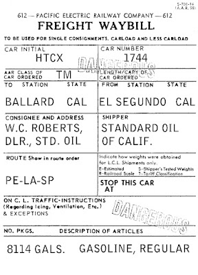
On a related topic, in previous posts, I have mentioned a number of things about the rubber stamp images one sees on most waybills. One example of an interesting variation is the “open” lettering used for a “dangerous” stamp in one bill I have seen. It was shown among a discussion of tank car waybills (see it at: https://modelingthesp.blogspot.com/2023/03/waybills-part-107-tank-cars.html ), and just the part with the stamp is repeated below.

This makes a change from the “solid” lettering of danger stamps shown earlier. One can also rotate the stamp so that it looks quickly applied, as in this model example:

These additional details of waybill content continue to interest me, and I continue to add them to my model waybills as appropriate. It’s my goal to make my layout operating sessions increasingly realistic through improved paperwork.

 Tony Thompson

Friday, July 7, 2023

Those SP reefers

 I posted previously about the quite rare Southern Pacific reefers: rare because, of course, all SP’s needs for commercial refrigerated traffic was filled by Pacific Fruit Express and its immense fleet of PFE cars. I wrote a post about the SP refrigerator cars a few years ago; you can read it at: https://modelingthesp.blogspot.com/2019/01/southern-pacific-refrigerator-cars.html

To summarize, these were cars originally purchased by the El Paso & Southwestern, and inherited by SP in the 1924 takeover. SP renumbered them to 37320–37339. By the time I model, 1953, the Official Railway Equipment Register (ORER) shows that there were still seven in service. I decided to model one.

Without a desire to make a meticulous model of this rare car, I decided I could use the Accurail wood-sheathed reefer as a basis. It is certainly the right length and the right proportions. It appears that SP painted these cars with yellow sides and boxcar red (BCR) roofs and ends, despite (or perhaps because of) the familiarity of the Daylight Orange sides on PFE reefers. Accurail offers an undecorated wood-side reefer in the yellow-BCR colors.

Construction of an Accurail kit, of course, is quite simple and won’t be described. I did include the fishbelly center sill, since we know the prototype cars had them. Below is a Paul Darrell 1941 photo (from the Sheldon King collection) showing a full side view of one of these cars. This is a repeat from the post linked in the first paragraph of the present post; you can click on the image to enlarge it if you wish.

Before continuing with the modeling, let me mention that the above photo shows only the initials “SP” as reporting marks, correct in 1941, but after 1946, the road name was spelled out as the reporting mark, so for my 1953 modeling, I needed to do that also. And in later years (compare the 1949 photo in the preceding post, linked in the first paragraph of the present post), the word “refrigerator” was smaller. Other evidence indicates that in later years, the painting of safety appliances and door hardware black was abandoned.

Next came lettering. I used a couple of different decal sets, mostly the Tichy set with my own artwork for SP tank cars. I took the word “refrigerator” from a URTX set. Arrangement of lettering doesn’t exactly match any of the photos I have, but all three photos differ from each other.

In the photo above, you can see one other things I did in assembling the kit: I added a brass brake staff and brake wheel (see my post on preparing those parts: https://modelingthesp.blogspot.com/2023/05/small-project-replacing-brake-wheels.html ). In the photo, it’s not painted yet.

I assembled the Accurail underframe as intended, except for cutting the steel weight in half and gluing the two halves atop each other with canopy glue, as I’ve shown before (in a post at: https://modelingthesp.blogspot.com/2016/04/upgrading-simple-freight-car-kit.html ). I also tapped the truck and coupler-box holes for 2-56. I have not had good experience with the Accurail friction attachments. I added InterMountain wheel sets to the kit truck frames.

With that work completed, the body and underframe were joined and given a coat of Tamiya flat finish preparatory for weathering. I followed my usual regimen with washes of acrylic tube paint (see the posts linked under “Reference pages” at the top right of this post). Once the weathering was protected with another coat of flat finish, I added reweigh and repack stencils on paint patches, chalk marks with a Prismacolor white pencil, and route cards. 

This car will only appear occasionally at the ice house on my layout, probably picking up ice in my town of Shumala to deliver for passenger needs (ice-activated air conditioning) at nearby San Luis Obispo, or to section houses in the area. But it captures, even if approximately, a real rarity in the SP car fleet.

Tony Thompson

Tuesday, July 4, 2023

Trackwork wars, Part 6

 From time to time in this blog, I have related the challenges of maintaining trackwork (nearly all of it installed long ago). “Maintaining?” you may exclaim. And yes, most of it is indeed commercial track components, yet maintenance is still required. 

An area that continues to baffle me is the change in gauge of commercial turnouts, particularly Peco turnouts. This concern goes back some years, and has not ended (see my initial attack on this, in a 2018 post: https://modelingthesp.blogspot.com/2018/07/trackwwork-wars-part-2.html ). In each operating session that I host on my layout, I keep notes of any and all problems encountered by crews. Lately there have been some problems with track gauge, again.

All I can do is go around the layout, checking not only the track switches where problems occurred, but all switches. Of course the NMRA gauge is my friend in this. Here I’m confirming the corrected gauge in the yard lead at Shumala.

When a problem is found, almost always tight rather than wide gauge, I either use pliers to change rail curvature, or use files to widen the gauge.

[I should mention that I have always been very careful to check gauge in commercial switches before installing them. Back when I was first building extensive trackwork, over 30 years ago, the standard of the day was the Shinohara line, and I found, as did many others, that about one Shinohara in ten had distinctly tight gauge through the frog. You couldn’t fix it. They simply had to be discarded. Ever since, I have very carefully checked every switch before installation. So I am confident that the track gauge problems I describe in this post occurred after installation.]  

One area of continuing issues is the three-way Peco switch in front of the Santa Rosalia depot. I have had to correct the gauge several times. Here’s a check after correction:

Another place that was fine for years and recently acted up, is the house track switch at the Ballard depot. Again, gauge had to be corrected. This is an old Shinohara switch, which certainly would have been checked before the original installation. Now it’s fine.

Another area of past trouble is the switch off the branchline main to Track 7 at the rear of Ballard. There was only a short segment out of gauge this time.


Lastly, a Peco switch for which I have had to widen the gauge through the frog at least three previous times, and now it needed a bit more widening. It’s in my East Shumala area, the switch that gives access to the two industry tracks.

I continue to be baffled as to what is causing this. Where I live, Berkeley, California, we have neither winter nor summer temperature extremes, nor extremes in humidity, that might affect benchwork as well as track. Perhaps the plastic into which the rails are molded in commercial turnouts is shrinking for some reason.

So in summary, even on a layout with some areas that received track two decades ago, and none less than five years ago, trackwork needs checking whenever an op session has found any problems. That was how the areas shown in this post came to my attention. So I can’t say “lesson learned;” it’s more like “lesson learned one more time.” But I’ll be ready for the next op session.

Tony Thompson

Saturday, July 1, 2023

Standards for layout freight cars

Everyone has some kind of standards for freight cars in their fleet, though they may well be implicit rather than stated explicitly or written down. I have written about this topic a few times in the past in this blog, but thought it might be useful to summarize some of my previous points again, as well as describing some new perspectives I have developed. 

I first touched on this general subject area in a post back in 2011 (see it at: https://modelingthesp.blogspot.com/2011/03/model-freight-car-standards.html ). In February 2017, I wrote one of my “Getting Real” MRH columns on this topic, and there is a blog post describing that article (the post is here: https://modelingthesp.blogspot.com/2017/02/my-column-in-february-issue-of-mrh.html ).  A little of that material is repeated below.

Although I divide my freight cars into mainline and branchline cars, meaning cars which are or are not of sufficient quality (accuracy and detail) to withstand scrutiny when stationary or in switching moves, there are some basic standards applied to all. 

These standards can be divided into three groupings: performance, detailing, and weathering. But weathering has been well covered in my “Reference pages,” linked at the top right of every post, so I will discuss that topic more briefly.

Performance. The primary aspects here are trucks and couplers. Trucks need to be free-rolling, have metal wheels,  and in tram, that is, with axles parallel to each other and perpendicular to the sideframes. Any truck which can get out of tram not only will generate higher friction, but facilitates derailments. Both these criteria depend on wheelsets of the correct length. An axle which is too long prevents free rolling, and one which is too short can allow out-of-tram behavior. 

Many of my freight cars still have Kadee “wide tread” wheelsets, but new cars and most upgrades for a number of years received Reboxx wheelsets of appropriate length. I regard their performance as outstanding, and I like the appearance of the 0.088-inch treads. Since Reboxx products disappeared, I usually use InterMountain or Kadee wheelsets with the 0.088-inch treads.

 The standard coupler on my entire fleet at one time was the Kadee #5, and these are still on many older cars. But all new cars and many upgrades received the “scale head” Kadee #58, #78, or one of the whisker-sprung models, such as #148. These interact acceptably with the #5 but are best with other scale-head couplers, so I expect a gradual increase in the proportion of scale heads in my fleet. 

I have not accepted any of the “copycat” couplers made in China, and routinely replace them with Kadee. I have tried the Accurail scale coupler and have not found it superior to the Kadee scale head.

With couplers it is vital to ensure correct coupler height, and free operation of both the centering mechanism and the knuckle. I am careful about this with new cars, but do find that maintenance sometimes requires restoration of one or more of these qualities. In fact any car which does not couple smoothly and dependably goes straight to the workbench for correction. The same is true of any trucks which do not perform as desired.

My testing of coupler height and trip-pin height are carried out on this test track given to me by Jim Ruffing years ago. It has Kadee gauges at each end and an Atlas re-railer in the center. It’s a quick and easy process to check any car. I use it all the time to check newbies, repairs, or cars that have not performed well.

All these aspects and more are checked in my “rookie test”  (for example: https://modelingthesp.blogspot.com/2018/07/the-rookie-test.html ), and subsequent posts enlarged the topic with more detail about the procedure in later years (see one of them here: https://modelingthesp.blogspot.com/2020/05/healing-sick.html ). It’s routinely applied not only to a new or repaired car ready to enter service, but to any older car that exhibits any problems in operating sessions.

My rookie-test record is a form like the one below (not exactly, but generally like this), so that I know whether adjustments were needed on a car, and which ones. It also includes a switching test, with moving a string of cars, including the test car, through closely-paced No. 5 switches to check for overall performance, as described in the two posts cited in the previous paragraph. 

Detailing. This is a difficult area about which to generalize, given the differences among car types and the wide variety of commercial models of each. But I can describe a few guidelines which I use.

Car roofs are very visible on most layouts, given the common table heights we use, so I start with the running boards on house cars. The bad old days of terribly thick cast plastic running boards (so 20th century!) are fortunately behind us, but it’s still essential to make sure running boards look right. 

As I model 1953, prototype cars built since 1946 would have received steel grid running boards, as would many cars in shops for repair or upgrading. Etched metal boards are simply the best, in my opinion, though I think the Kadee plastic effort is impressive. I use model airplane canopy cement to attach the metal boards, since that adhesive remains flexible in the face of expansion and contraction of the metal part.

Wood running boards are readily modeled with wood or styrene strip. Corner grab irons need to be there too, and though some of  my mainline cars still have cast-on corner grabs, branch cars do not.

Nowadays most house car models have acceptable brake wheels (the most common prototype make was Ajax), but as more and more of the prototype specialties have become available (Equipco, Superior, Klasing, etc.), it’s often possible to apply the correct brake wheel for a particular prototype car. I don’t always do this, and sometimes it’s not easy to find out which brake gear to use, but laying in a stock of the various prototypes permits doing it correctly when the information is available.

Grab irons need to exhibit adequate refinement. Cast-on ones are certainly candidates for replacement (except on a few of my mainline cars), and the heavy bracket grabs of early IMWX and Red Caboose cars can readily be replaced with the current InterMountain parts, available for purchase as parts sprues.

Modern kits and RTR cars usually have acceptable sill steps, though often rather fragile when made of plastic. Any cast-on ones are usually replaced with A-Line metal steps, as are damaged plastic ones. I still have some remaining stock of Tuttle steps, a slightly more refined part than the A-Line steps, and I tend to use them on models I regard as more important.

Underbody detail is not something I put a lot of work into, other than making sure that some brake rodding is visible from the side of the car. As Richard Hendrickson used to say, I intend my trackwork to be good enough that visitors will not get an inverted view of my freight cars. Hopper, covered hopper and tank cars are an exception, as their brake rigging is much more visible and needs to be correctly modeled.

Weathering.  I do weather almost every single car. Photos of prototype cars only a month old already show some dust and dirt, so the myth of the “freshly painted car” really does not go very far. As I mentioned in my post on weathering PFE cars (see http://modelingthesp.blogspot.com/2011/03/modeling-pfe-reefers-in-1953-2.html ), one should attempt to create a wide range of levels of weathering, though most people (including me) don’t seem able to get all the way there, particularly to the truly filthy dirt jobs. But at least a few cars should be so modeled, perhaps with a “wiped clean” area around the reporting marks and number for those of us who operate with waybills and car cards.

Some cars, like tank cars, can be a challenge to weather convincingly; and open-top cars like gondolas and hoppers are a complex challenge because the interior is usually at least partly rusted, if not entirely unpainted. Each person has to find the weathering method that works best for them and then go to work.

These are my most general standards. Beyond these, description becomes more intricate than is probably necessary here. Modeling challenges to represent specific prototype cars is an allied but different subject, and I will continue to address it in future posts.

Tony Thompson