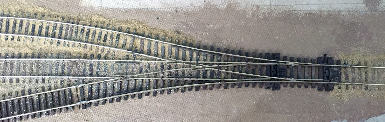
At the far end of my Santa Rosalia branch there is a switchback connection to an industrial spur and also a siding on the main line. The most compact way to switch this is with a three-way turnout. I used the Peco Code 75 asymmetrical turnout here, their number SL-E199. It’s an excellent product and mechanically it works flawlessly. It’s shown below installed, with some ballasting remaining to be done within the turnout itself. It’s called “asymmetrical” because the two throwbars, visible here, are at different locations, and the two side tracks diverge asymmetrically from the center track. On my layout, as this photo illustrates, the upper diverging track is a siding off the main, and the lower one is an industrial spur.
Peco supplies an instruction sheet for this, which can be found at: http://www.peco-uk.com/imageselector/Files/Instruction%20sheets/HO-OO%20Code%2075%203-Way%20SL-E199.pdf .
Electrical connections with this kind of turnout are necessarily complex, with two sets of points in close proximity. Peco recommends using a pair of their own SPDT (single pole double throw) switches here, in combination with two of their switch machines (which they call “point motors”). I like their switch machines, which are sturdy and dependable, but they do require a rather mammoth hole in the layout to place them, and then they are buried under the track and scenery. Or you can excavate that big hole clear through the track support (Homasote plus plywood or whatever you use), and then the switch machines are accessible from below. I didn’t really want to follow either path.
I had the thought that the turnout could remain hand-thrown, as Pecos are designed to be, and then I could do the electrical power routing with a couple of switches. But when I contacted Peco through their modelers’ online Q & A, they replied that it wasn’t really possible, but that you had to use their own switches and, preferably, their own switch machines. Since I didn’t want to do that, the situation immediately became a challenge, and I decided to see how I could do it.
Checking my stash of electrical parts, I have a bunch of double-throw switches, but not SPDT ones, so I decided to just use what I have. As Peco themselves observe, there are a number of ways to wire this turnout, so I chose one that appeared like it could work for me.
Below is the Peco diagram for this switch, which, please note, is viewed from the bottom. (That is why the drawing is, if you will, reversed in its asymmetry from the photo above.) The switch is delivered with the three wires (numbered 1, 2, and 3) already installed. This diagram shows the Peco SPDT switches installed, which I wasn't going to do.

I decided to wire the contacts of two electrical switches. Essentially one pole of one switch connects the South track feed to both wires 2 and 3 (the siding), while the other pole connects the North feed to wires 1 and 3 (the spur). I used the second switch to serve the main (center) track, connecting North to wire 2 and South to wire 1. I used a DPDT (double pole, double throw) switch for the main track contacts, and a 4PDT switch to handle the siding and spur contacts (I could have used two DPDT switches but had a 4PDT one on hand).
This of course made a bit of a maze of wire behind my small control panel (the construction and decoration of that panel are shown in a prior post (at: http://modelingthesp.blogspot.com/2016/12/progress-at-santa-rosalia.html ). But that’s just a matter of getting all the wires in the right places. Most of this is no. 22 wire, big enough for leads of three inches or so to the terminal strip.

With this wiring complete, the panel could receive final installation on the layout edge at Santa Rosalia. Here is its completed appearance, with all lettering.

The panel was apparently wired correctly, since tests with switcher SP 1423 were fine. Here is the switcher moving a PFE car to Coastal Citrus on the spur for the first time.

It will be nice to have all the switching at Santa Rosalia enabled, and will bring three more industries into play, which is always interesting. I built the Coastal Citrus structure some years ago, and it’s been waiting for quite awhile for the railroad spur to reach it! Now it does.
Tony Thompson
Having two Fast Track built 3-way switches I feel yer pain. I isolated both frogs and wired a single lead from each of the frogs to a frog juicer. Installed ground throws for each set of points and it's done. No Muss no fuss wiith electric switches DPST or otherwise. The system's been inplace for several months now and works flawlessly.
ReplyDeleteHarryBH
Thanks for mentioning the Frog Juicer. I have found them tremendously effective on regular turnouts, and I did wonder about doing the same for the 3-way. If I get tired of the 3-way switch settings, I may go back and replace with Frog Juicers.
ReplyDeleteTony Thompson