Sunday, October 31, 2021

Out-of-town operating, Part 2

 In the previous post, I described two of the layouts on which our California contingent operated in the La Crosse, Wisconsin area during our week-long trip to Wisconsin and the Twin Cities. I don’t mean for these posts to be “diary-like,” only to provide information about a few layouts and to thank again the outstanding hospitality of everyone we met on these excursions. That first post is here: https://modelingthesp.blogspot.com/2021/10/an-out-of-town-operating-trip.html .

Our California group was Seth Neumann, Jim Radkey and Ed Slintak, along with me, from the Bay Area, and Al Daumann from Southern California. All of us, like all our hosts on the trip, were fully vaccinated, a factor in these uncertain times. 

The morning of the second day we operated at Steve Brudlos’s superb Milwaukee Road River Subdivision, set in the transition era: a very large layout, and beautifully scenicked. I will just show a few of the many photos I took there. This view is at the town of Wabasha, with Nancy Stearns switching the yard (we later visited the fine CB&Q layout under construction by Nancy and her husband Scott).

The overall effect in every area was very well done, but to me more impressive was the level of detail in every scene. Here is a road crossing in the town of Winona, using a mirror so that the road disappearing into the trees isn’t heading into a black hole. But notice all the other details: lampposts, sidewalks and curbs, and the nice treatment of the asphalt road.

My assignment here was switching the town of Winona, and a semi-schematic map helped greatly. You can readily see the complexity of trackwork and can probably imagine the corresponding complexity of switching needed. It was great fun! and of course a delight in the midst of such excellent scenery work.

In the afternoon we operated on an even bigger layout, Ron Copher’s Lake Erie and Southern. The size was just overwhelming. Below I show one of the long aisles, double-deck on both sides. I did have one road job, and it was really enjoyable to run through all this territory.

My main assignment here was as the engineer of one of the two yard switchers. I had plenty of work to do, which was fun, and you can see from this photo that I could hardly see to the other end of the yard. It often felt like I was operating alone, though in fact the yardmaster directed the work of both yard switchers. Incidentally, that’s Iowa’s Doug Harding at right.

This wrapped up our time in Wisconsin, and it was on to the Twin Cities for the remainder of our trip.

As was the case for the other La Crosse-area layouts, we were very impressed with the quality we saw on Tuesday, and cannot give too high a recommendation for the biennial RiverRail event that these folks host. If you get a chance to attend a RiverRail, don’t fail to go!

Tony Thompson

Thursday, October 28, 2021

An out-of-town operating trip!

 Last week, several local California model railroad operators paid a visit to the Twin Cities and to La Crosse, Wisconsin. It all began with Rich Remiarz and me, exchanging emails about how it would be fun to visit and operate on a few layouts as the pandemic eases, and ended up with five Bay Area guys traveling to the Midwest for an intense, week-long trip. (I should mention that everyone involved, guests and hosts, was vaccinated.)

We began with four layouts in two days in the La Crosse area. The hospitality, headed up by Dave Burman, was really first-class, and they even made up name tags for us, taking off from their biennial Riverrail event.

First up was Dave Waraxa, whose BNSF Kootenai River Sub was really a good-looking and enjoyable layout to operate. I chose the Potlatch Mill job, a challenging complex of mill trackage. I show Dave’s semi-schematic map of the mill below, and this was a guide for ongoing inbound and outbound switching, exchanging with the adjacent yard.

The area was nicely modeled, as you see below, with the switcher pair in the foreground, and with the wide variety of cars to be switched, really interesting as a job (of course, all the tail tracks were too short! making the job that much more interesting). The morning flew past!

That afternoon, we moved to Al Lesky’s Milwaukee Road River Division, another layout with some challenging switching jobs. I chose the Red Wing job. This includes the large Red Wing Malting complex, shown below, along with Red Wing Shoes, as well as Cargill  and ADM elevators. All involved moving a lot of cars!

This complex was nicely provided with clear directions on the switching to be done, and train interactions. A nice job and well thought out. In the schematic below, Red Wing Malting is at lower right.

That evening we all converged on the Freight House restaurant in La Crosse (originally an actual 19th century freight house) for a nice dinner — classy logo below.

Terrific venue, good food, and a fine end to an excellent operating day. But it was only the beginning of the week! More later.

Tony Thompson

Monday, October 25, 2021

An SP company-service tank car

 I was recently thinking about adding another Maintenance of Way (MOW) tank car for Southern Pacific. Certainly in the steam era, these seemed always to be on the MOW rosters. I already operate two of the old Westside brass cars, models of SP Class CS-25A, and these often can be seen on the “outfit track,” as SP called tracks for MOW use, in my layout town of Ballard. Here’s SPMW 7424:

But even older cars are often seen in transition-era photos. In looking through some old drawings, I happened onto the drawing shown below (SP drawing; original, ink on linen, 8 x 16 inches), dated August 1892. This drawing was also reproduced in my Volume 5 on tank cars, in the series Southern Pacific Freight Cars (Signature Press, 2008). You can click on the image to enlarge it if you wish.

The car is named as a “distributing car,” doubtless meaning distribution to company facilities. Its three compartments are a large center space, 4000 gallons in size, for “coal oil” (kerosene), a left-end compartment of only 800 gallons, for “signal oil” (a slow-burning petroleum product used in lanterns and signals), and at the right, a 1200-gallon compartment for “mineral seal,” a petroleum product mostly used as a solvent and for cleaning. Total capacity, 6000 gallons.

Whether this car was built or not is not certain, but from the 1890s into the mid-1920s, there were two three-compartment cars carried on the SP revenue roster, SP 56198 and 56199, the latter being a 6000-gallon car like the drawing above. It is certainly possible, then, that SP 56199 was the same as the drawing, though no photographs have ever surfaced as proof.

But there may have been a successor. In 1928, Los Angeles General Shops assembled a “new” distributing car using “surplus materials,” as its car card (at CSRM) stated. Paul Darrell photographed SPMW 3721 (Sheldon King collection). This is actually a CS-35A flat car with the tank mounted on it. Whether any of the parts of the old SP 56199 were used is not clear, but probably not. The tank sections are all double-row-riveted, something certainly not practiced in 1892, and the same goes for the safety valves, not included in the 1892 drawing. But since this car was dismantled in 1950, it’s not an option for my 1953 modeling era.

What else could be done? Some quite old tank cars did survive in SP company service. How might one go about modeling such a car? There is one simple possibility, the old LaBelle “Texas Midland” tank car kit. As intended to be built, it reproduces an early 20th century tank car. For an example of what these looked like, late in their lives, here is another Paul Darrell photo (Sheldon King collection). This car, SPMW 7698, has five courses of tank sheets, as did most SP Class CS-12 and -12A tank cars.

The LaBelle car is set up to be built with seven courses of tank sheets. Below is a photo of a partly completed LaBelle kit that I purchased at a swap meet awhile ago. Obviously the builder was working toward a MOW car, probably somewhat like the photo above. One could readily change the tank sheets if desired, but my own feeling is that they aren’t very obvious.

The most obvious need on this car is the side railings. I have an idea how to make a reasonably sturdy version of what you see above on SPMW 7698, and may proceed with the project. Photos of many SP MOW consists show that they included a water car, and this could be one. Progress on this will be reported in a future post.

Tony Thompson

Friday, October 22, 2021

Waybills, Part 92: identifying commodities

 Waybills, of course, were the documentation for movement of freight. The freight had to be identified on the waybill, so that the correct freight rate would be applied. Over time, a system of “commodity code numbers” emerged, so that each of very many thousands of possible cargoes could be uniquely identified. Well, kind of. Let me explain. 

As late as the mid-1960s, many cargoes shown on prototype waybills simply used ordinary English descriptions of what the cargo was. The waybill blank had a place to enter the commodity code (shown below). The red arrow indicates the code box (you can click on the image to enlarge it if you wish.) Here the cargo, “Class 45 scrap,” was given no code.

My impression from examining a moderate number of prototype waybills from the 1950s and 1960s is that this box seems to have been used in a minority of cases. Likely the agent making out the waybill knew the freight rate for everything his local shippers would load, so the code wasn’t essential

The standard reference document for freight descriptions via the commodity code was the Uniform Freight Classification, as I briefly described some years ago (see that post here: https://modelingthesp.blogspot.com/2012/02/waybills-18-resources.html ). The 8th issue of that volume, dated September 1966, was shown in the post just cited, and I repeat the photo here. The book is 8 x 11 inches in size, and more than 1.5 inches thick.

Within the book, there are two sections, about equal in size. One lists commodities in alphabetical order; the second lists them in numerical order by commodity number. As might be expected, many entries in this volume are in the classic Army nomenclature, principal name first, as in “bag, sleeping, Arctic.” Others however are in plain English. 

And in prominent use throughout the classification is the abbreviation, “noibn,” meaning “not otherwise identified by name,” used for all sorts of generic groupings. For example, “mechanics’ hand tools, noibn,” thereby describing a miscellaneous assortment of tools. Here is a brief sample of what entries look like. You will see “noibn” amongst these entries, along with “iors,” meaning “iron or steel,” and “nnstd,” meaning “not nested.”

For model use, the prevalence of “plain English” commodity descriptions in prototype waybills is welcome, as it frees us to give brief and informative descriptions. At the same time, though, sometimes the official classification language serves well, as in the following instance. 

I was aware that spent brewing malt retained food value as animal feed, and was often shipped in bulk. Accordingly, I looked up the official classification, and used it in the model waybill you see below.

The car identified above is one of the recent InterMountain ready-to-run cars, with added weathering, route cards, and chalk marks (fulfilling Richard Hendrickson’s dictum that models like this really aren’t “ready to run” but really instead should be regarded as “ready-to-finish”).

I continue to make use of the Uniform Classification as a double-check on some of my freight categories, but have not gotten into commodity codes on my waybills, and will not. That would be just a little too much information. <grin>

Tony Thompson
Tuesday, October 19, 2021

Chromite mining on my layout

A few years back, I wrote a description of the kinds of published information that a modeler can use to find out about mining activities in a particular area being modeled. Of course, if you are modeling West Virginia or the Mesabi Range, you are not in doubt about mining issues, but there were more modest mining areas throughout the country. That post can be found here: https://modelingthesp.blogspot.com/2016/10/modeling-mining-in-your-locale.html

I followed up that post, which ended up describing a little about chromite mining in California, with more information about the mineral itself, and some progress I had made in making ore cars and suitable loads. (See that post at this link: https://modelingthesp.blogspot.com/2016/10/modeling-mining-part-2.html ). In the present post, I return to this topic. 

I have chosen the name of an actual mining operation in the vicinity of my layout locale, Monarch Mining, as the shipper of ore, ordinarily the kind of “disseminated” ore described in the post cited in the first paragraph, above. This ore contains a moderate amount of the target mineral, chromite, in a matrix of serpentine. 

I envision this ore being en route to a facility that refines the ore to separate the chromite, and then makes high-temperature refractory brick, one type of which includes chromite in the brick composition. 

And just to repeat what I’ve said before, the term “ore” is an economic one: it means a mineral that can be economically mined and refined for use. The identical mineral that is more difficult to mine, transport, or refine would no longer be considered an ore.

To transport chromite ore on my layout, I have continued to work on 70-ton ore cars, as I showed in the post just cited, and have increased the size of the fleet. But where would ore come from? Despite the fact that having “a mine” on a layout is a cliche dating back 80 years or  more in the hobby, I don’t have one and don’t want or need one. Instead, I could model a truck dump; or simply let the mining company load cars at a team track.

So even in the absence of a truck dump on the layout, loaded and empty Monarch ore cars can be seen, for example as in this photo at Shumala. These cars, MMCX 217 and 241,  are evidently waiting for pickup by the next SP local.

As I have mentioned in previous posts, I also used a Grandt Lines kit for a Gilpin Tram ore car, simply adding HO scale detail parts, trucks and couplers to the O-scale car body. This makes a more reasonable size ore car for my use. I have one of them labeled for Monarch Mining, as you see below in another cut of ore loads at Shumala, waiting for pickup.

In addition to these carloads of ore, Monarch would presumably receive various kinds of repair parts and supplies for its mining operation. These can be directed to a team track for the time being, until I can figure out where to add an office or warehouse for Monarch on the layout. Or, of course, like many industrial users of rail shipment, there really need be no Monarch building visible anywhere on the layout, with any shipments going via team track. 

Here’s an example waybill to represent such an inbound shipment. The Hardinge Company, headquartered in York, PA,  was and is a real concern that once manufactured many kinds of equipment including mining and milling equipment. Today they specialize in metal cutting equipment. They continue to have warehouses all over the world; in the transition era one was in Salt Lake City.

Here is a photo of the shipment just described, being spotted on the team track in Ballard on my layout. I have shown this load previously, in a post about removable loads, especially crates, for open-top freight cars  (see it at: https://modelingthesp.blogspot.com/2012/03/open-car-loads-crates-and-machinery.html ).

So as I have mentioned before in several places in this blog, I do represent mining on my layout, despite the fact that California in this or the previous century wouldn’t be considered a major mining state; and I neither intend nor want to model an actual mine on the layout. I just depict the traffic.

Tony Thompson

Saturday, October 16, 2021

SP car ledger donation, Part 2

 In the first post on this topic, I showed the appearance of the so-called “car ledgers” of the Southern Pacific (formally, Freight Car Records), with car fleet history from 1920 into the late 1950s. I described the contents in a broad manner, and listed the titles of the eleven volumes of surviving ledgers  — all have now been donated to CSRM (California State Railroad Museum). That post is here: https://modelingthesp.blogspot.com/2021/10/sp-car-ledgers-donated-to-csrm.html

I should give a little background. As the merger of SP into Union Pacific approached in 1996, many items of historical or economic interest vanished from offices and shops around the system. These ranged from original oil paintings in the headquarters at 1 Market Street, San Francisco, to individual tools in many shop buildings, and of course historical materials of all kinds. 

The set of car ledgers that is the topic of this post was no exception, and a single employee managed to take them all home. I will not identify that individual, but will just say that when the location of the ledgers was determined, Steve Peery and I approached that individual to persuade either a sale or a donation to CSRM. 

No prizes for guessing which one. Steve and I split the considerable price (which will now become a tax deduction), after being told that the alternative was for individual volumes to be sold separately on eBay. Had that happened, likely several or most of them would never have been seen again. But let’s get back to the contents of these books.

In the previous post, I mentioned the headers of the pre-printed Form 4589 pages. One is shown below, which happens to be for Class A-50-6, the famous “door and a half” wood-sheathed automobile cars, once the subject of a popular Ambroid kit in HO scale, and more recently of an excellent Funaro & Camerlengo resin kit. You can click on the image to enlarge it if you wish.

Quite a few details of the construction are shown here, including such specialties as the Bettendorf truck sideframes, Camel door devices, and Simplex truck bolsters, along with many detailed dimensions. Below the header are the individual columns. Here the one of interest to modelers is the installation of geared hand brakes (column 7), meaning Ajax brake gear in most cases. Note also that some repetitive entries are made with rubber stamps.

For just one example of the extensive car records themselves, below is a single page of Class B-50-15 box car histories. These record when and where the car was steel-sheathed (if it was), where and when any changes of trucks were made, and when and where it was renumbered into a six-digit number (and that number is shown). Finally, dates and places of scrapping or sale outside of SP are also shown if that occurred during the life of this record volume.

Note furthermore that the records for these cars were so extensive that the facing page includes additional columns of information about the same cars whose numbers are shown on the left page. In other words. these are double-page entries for an entire class of cars.

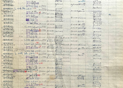
Finally, let me show a closer-up view of what these records look like. Here I return to the Class A-50-6 records mentioned above, to show complete lines of some of the entries.

Among many interesting details, note the renumbering of some cars into 52000-series numbers, just to the right of previous car numbers. These denote conversion to wood-chip cars with roofs removed. 

For a more close-up example, here are some of the entries for Class B-50-15 box cars. As with the automobile cars shown above, the car numbers crossed out denote removal from revenue service.

I suppose it is obvious, but records of this degree of detail permitted me, in writing the five-book series, Southern Pacific Freight Cars, to have detailed historical knowledge, not only of how each car class was built, but how it was changed during its lifetime, up to and including scrapping date. These ledgers were a critical resource. 

It should be mentioned that three categories of cars, covered in two of these record books, are only briefly covered. They are maintenance of way cars, cabooses, and passenger cars. In each of those cases, SP maintained “car cards,” 5 x 7-inch index cards, one for each car, that are far more detailed than what is in these record books. Luckily, at least two of those sets of car cards survive. The authors of two SP car books, a caboose book and a maintenance of way book, used the car cards as the primary reference. Nevertheless, the Record volumes are complementary to those sets of car cards.

The ending date of use of these volumes is not known for sure. Although someone in the Mechanical Department did make a few entries later than 1957, in general, the use of these Record books was ceasing about that time, as SP records of many kinds were being transferred to computer data management and storage. Little if any of the information in later days has survived in the kind of form shown in these Record books. But at least these books are now at CSRM.

Tony Thompson

Wednesday, October 13, 2021

A Pollock hot-metal car, Part 2

 In the preceding Part 1 on this topic, I described some of the history of this long-lived kit for a distinctive car, which is essentially a 70-ton ladle on a support structure with trucks. I also began description of building one of these kits, one that was missing a few of its minor parts. That post can be seen here: https://modelingthesp.blogspot.com/2021/10/the-famous-pollock-hot-metal-car.html . In the present post, I complete the car.

But first, I was (perhaps) justly criticized in an email for not saying anything about the prototype and its maker. Fair point. The William B. Pollock Company of Youngstown, Ohio produced a wide variety of ladles, slag cars, and hot-metal cars for the metal-producing industries for many years. Founded in 1863, they made their last shipment in 1983, as documented in the photo below (from this interesting site: http://www.therustjungle.com/rustjungle/2016/11/1/william-b-pollock-co ).

 Note here in particular the company name at lower right, with the triangular letters “O.” This is represented on the model car in just this way.

Assembly of the Pollock ladle itself that forms the “load” for this car was described in the previous post. Now my attention turned to the car itself. My first challenge was that only one of the formed brass covers for the coupler boxes was in the kit. No real problem, I simply made a white styrene copy of the brass one. The two covers are shown temporarily installed below.

The next step was to attach the brake gear castings. These sit on top of the car deck, and the brake gear components themselves are inside an enclosure, no doubt to protect them against spills of molten metal. 

The kit directions instruct you to drill through one of these, to insert a one-piece brake wheel shaft. I just made a separate shaft on each side. My kit happened not to have the brake wheels any longer, so I substituted Kadee no. 440 brake wheels. Here is the upper side of the car at this point.

For truck attachment, as seen above, I simply tapped the holes in the kit casting for 2-56. 

Next came paint. The prototype, we are told, was usually gray, with or without highlighted black on the letters, “POLLOCK.” I decided to use gray also, and chose Tamiya TS-32, “Haze Grey.” I haven’t decided whether to highlight the lettering.

One might perhaps ask at this point, what would I do with this model on my layout? After all, the layout has no steel mill, Pollock’s major customer type. Nevertheless, I have a large industry, Jupiter Pump & Compressor, which includes a sizeable foundry, and a Pollock car like this might be used there. And of course the car could be glimpsed in a passing mainline train, on its way to be delivered somewhere else.

For either kind of load destination, the car would be likely to be delivered as a load on a flat car, rather than moving on its own wheels. I have already shown a method to model that kind of flat-car delivery (you can see that post at: https://modelingthesp.blogspot.com/2021/06/railroad-equipment-on-flat-cars.html ). Here’s the Pollock car, loaded on a 70-ton flat car.

It was fun to research and assemble this classic HO-scale model. I will certainly work it into an operating session occasionally. Now to make up some waybills . . .

Tony Thompson


Sunday, October 10, 2021

SP car ledgers donated to CSRM

 Many readers of this blog (or of my five-book series, Southern Pacific Freight Cars) will know that Southern Pacific kept large book-style ledgers with detailed information about the repair and upgrading history of its entire freight car fleet. The first set of these ledgers was apparently begun at the very start of the Associated Lines era, circa 1900 or 1901.

Those early ledgers have been preserved at CSRM (California State Railroad Museum) for many years. They are extremely useful to the historian because they include many quite old cars that were still in service in 1900, though in many cases, not for long.

That set of ledgers was superseded in 1920, very likely at the end of the period of Federal control during the United States Railroad Administration (USRA) in March of that year. The new ledgers picked up all the existing cars, entries probably transferred right from the old ledgers, and continued forward well into the 1950s, until they were superseded by computer records. The latter, of course, do not survive, as all the archival tapes, tape drives, computer systems, and even software are long gone.

The ledgers begun in 1920 have now been donated to CSRM, to join the pre-1920 set. These large books have often been called “ledgers” (as I do here), both by those who used them, and by historians, though they are properly called (I am told) Freight Car Records. All consist of pre-printed page sheets, 14 x 17 inches in size, set up to record the origins of each car and its subsequent alteration or major repair, one line for each car.
 
What survived at the end of the SP are eleven volumes of these records. I will show a list of the titles of them shortly. You can see in the photo below that the pile of all 11 of them is about two and a half feet high; that’s a 12-inch ruler.

You can also see that they vary in external condition, though inside they are all pretty clean. The next photo below shows a single book, probably an above-average appearance, alongside the same 12-inch ruler. All are like this in that they have heavy cardboard covers, and most have printed canvas spines. Most of the books are on screw posts; a few have been counter-nailed closed. 

This particular book has the title on the spine, as do most books. In case it is difficult to read, the title describes hog fuel (wood chips), hopper, logging, and tank cars.

This set of eleven  books falls into two groups. The first group are the ones begun in 1920, and includes all cars existing at that time. Entries in these books continue into the late 1950s, as I will explain later.
 
The second group came into being after World War II, when SP first began to apply six-digit car numbers, at first to a few car groups, and a little later, to all existing cars (except stock and tank cars). The second group of books was created to contain records of existing cars under their new car numbers, as well as all new cars with six-digit numbers.

Here are the titles of the first group:
   Single Door Box Cars, classes CS-33 through B-50-14
   Single Door Box Cars, B-50-15 through B-50-27
   Stock & Auto
   Flat - - Gondola
   Hog Fuel - - Hopper - - Logging - - Tank
   Pass Cars
   M of W  - - Cabs
 
Here are the second-group titles:
   New Single Door Box Cars
   New Double Door Box Cars
   Spec Book (Specially equipped cars, box, gondola, flat etc.)
   New Gondola - - Hopper - - Flat

As a note, the “Spec Book” in the list above refers to cars having specialized equipment, and all the number groups of cars so equipped (types as listed) are shown above.
   
Next, I want to show the typical interior of these books.Below is a sample interior of the single book shown above. This spread happens to be part of the entries for logging cars, in this case the skeleton log cars of the 99000 series. These are the standard 14 x 17-inch pages.

These pages, like all pages in these books, are pre-printed forms (Form 4589) that were used for all car types. Each page has a heading, containing blanks for many aspects of car construction and original equipment. Below the heading are lines for individual car entries, and the column headings are originally blank, chosen later to record such things as truck changes, brake gear revisions, and upgrades or modifications. All such entries give the exact day the work was completed, and the shop where it was done. Visibly, these are nearly all handwritten.

I want to show more of the ways the book interiors look, and will return to that in a subsequent post. But the important message of this post is that these books are now preserved at CSRM.

Tony Thompson

Thursday, October 7, 2021

Those peaky coupler screws for brass models

 All of us who deal with brass models of railroad equipment (mine are HO scale), eventually deal with the metric screws that they have. Sometimes this is a hassle, sometimes not. Last year (partly at the request of an email inquiry), I wrote about modifying models to use or avoid the truck screws on these models. (that post is here: https://modelingthesp.blogspot.com/2020/09/those-pesky-truck-screws-for-brass.html ).  

(And incidentally, in the post just cited, I showed how I have made washers when replacing brass model truck screws of the shouldered variety, with straight screws. In fact, NorthWest Short Line offers quite a nice thrust washer which will work with most brass trucks, 2.0 mm ID and 4.2 mm OD, and they cost $1.29.)

Today I want to turn to coupler screws. Usually brass models have these screws in the box, but I have purchased second-hand brass that does not have any screws. And in at least one case, I carefully put the coupler screws for a brass model in a “safe place,” which was indeed very safe, because I haven’t found it yet. Either situation requires knowing what size these screws are so that you can replace them.

I thought to myself, “Well, this is a common problem, so it must be well covered on the Internet, one of the many times that ‘Google is your friend,’ no doubt, and I can just look it up.” Wrong. I could only find a couple of mentions of specific models, nothing in general. That’s why I wrote this post. 

Let’s begin with what you see. What you hope to find when you look at the coupler pad of a brass model is a combination of screw holes, both a pair of holes for the side shoulders on the Kadee coupler box, and a center hole. An example is shown below (a Challenger brass GS gondola). There is also a hole at the back of the coupler pad, which I’m told is for a European coupler box, but that’s hearsay.

Personally, I always prefer the center-hole mounting, and usually cut off the Kadee side-mount protrusions. That center screw is usually a 2.0 x 4 mm screw, preferably pan head. In the photo below, you see a Kadee coupler box, with “ears” cut off, installed with a 2.0 x 4 mm screw. The coupler is a #58.

I should mention that I have encountered locomotive tenders that did not have this 2.0 x 4 mm-size screw, but most brass models in my experience have this size center screw hole in the coupler pad.

Unless, of course, they don’t have a center hole, but just the two side holes (and that rear hole). An example of this is shown below. It happens to be a Precision Scale tank car, but I should hasten to add that many PSC brass models do have center coupler-mount holes. This particular one didn’t.

The screws for these “side” holes are usually 1.7 x 4 mm or 1.7 x 5 mm screws. The drawback now is that this coupler pad requires use of the Kadee coupler box side mounts, and on some model cars, they interfere with truck swing. Here is my installation, again a #58 coupler.

One solution, of course, is to drill and tap the center of the pad for a 2.0 mm screw. Now I know at least some readers who are asking themselves, where the heck would I get metric screws and taps and all that. For the 2.0 mm size, a 1/16-inch drill is the tap drill, but you still need a tap. 

NorthWest Short Line has sold these types of screws, along with tap drills and metric taps, for many years, and they still do (the screw offerings are here: https://nwsl.com/collections/screws ). The assortments are the bargain. But many on-line hardware suppliers sell metric screws and taps, so shop around.

I should also mention that I know U.S. modelers who hate metric screws and simply drill out the 2.0 mm hole and tap it for 2-56. That’s your call, of course. I confess to having done that on the brass locomotive tender I mentioned above, the coupler screw for which I just could not identify (and it wasn’t 1-72 or 0-80, either). But ordinarily I prefer using the screw holes that are provided. 

Tony Thompson

Monday, October 4, 2021

Completing a turntable

 About 35 years ago (!), I built a Diamond Scale turntable for my layout, then located in Pittsburgh, PA. I liked the kit and felt that the resulting turntable looked really nice. It worked fine, too, though I later removed the hand-crank mechanism as part of moving the layout to California. But the turntable itself actually never got finished. Many visitors over the years have seen it looking like this: 

The protruding ties, eye-catching because they are unfinished, are intended to support the walkway and handrail along both sides, and a cab for the table operator on the longer ties at lower right. I had stalled in progress on the project because of the kit’s directions for making the handrail. Here’s the drawing from the instructions:

Not only did this look like a difficult and fussy step to complete, keeping all posts parallel and vertical, but also the result was intended to be a wooden handrail structure, and with huge posts (the ties are about 10 x 10 scale inches). One could of course use smaller posts, but there’s a bigger question.

And that question is, what did Southern Pacific turntable handrails actually look like? In particular, were they like the intended result of the Diamond Scale kit? Was there a post at every long tie? How tall were those posts? and so on. Since my layout models an SP branch line, the turntable ought to reflect SP practice. 

The first answer is that SP turntables were definitely not all the same. Certainly there were wood handrails on some turntables, but particularly near and after World War II, quite a few of them had handrails made from pipe. I decided to examine some examples more closely.

I will begin with wood handrails. A wartime image at Dunsmuir, below, shows a Class F-5 2-10-2 on the turntable, and the handrails are clearly shown (Eastman photo, Shasta Division Archives), even it it isn’t a good view of any of the locomotives. This is certainly like the intended Diamond Scale handrail.

A second example, also a wartime image, is the turntable at Eugene. It’s a fine view of the turntable, clearly with a wooden handrail, with a longer span between posts than the Dunsmuir turntable shown above. It’s an SP photo, John R. Signor collection. And incidentally, also a nice view of the operator’s cab, which is quite similar to the Diamond Scale kit cab.
 

At this point, even though I was aware that many SP turntables did not have wooden handrails, I spent a little time figuring out how I would modify the Diamond Scale instructions to build a wooden handrail on my model turntable. My idea was to clamp something square near the ends of the ties, so that the posts could all be aligned, and individually squared up. Here’s a view of that arrangement, using a 1/4-inch square piece of hard balsa.

You can just see the ends of the long ties protruding beyond the edge of the balsa strip. I believe this method would yield posts well aligned, and thus ready to accept the longitudinal handrail boards that are seen in both the Eugene and Dunsmuir tables. The walkway could then be added inside the posts.

It was tempting to proceed with this process, just because I always like to build kits (mostly) as they are intended to be built. But as mentioned above, there were plenty of examples of SP turntables that did not have wooden handrails. I will take up those examples in a future post.

Tony Thompson

Friday, October 1, 2021

The famous “Pollock” hot-metal car

 Back in 1949, General Models Corporation introduced a white-metal kit for a Pollock hot-metal car in HO scale. General Models or GMC was almost entirely an O-scale business, begun in 1943 and eventually sold to All-Nation Hobbies in 1950 (for a fairly detailed history, see the Train Collectors’ page: http://www.tcawestern.org/gmc.htm ). Boxes for GMC models were quite distinctive, even for this orphan HO scale model among all the O-scale products; the box is about 7.5 x 3 inches.

The HO hot-metal car kit languished for a few years, then appeared again about 1954 from Ed-Lee’s Model Builder’s Supply Company in Duarte, California (not the current MBS that sells scenery materials!). Though the box was quite different (about 6 x 3.75 inches), the kit inside was essentially unchanged from the GMC kit. 

The kit was also sold briefly by Suydam, but I have never seen a box. After a period of unavailability, it was released again about 1972 by Buckeye Models in Steubenville, Ohio, initially as the same kind of cast metal kit (probably zamac).

The Buckeye kit was available for around a decade, then about 1985, it came onto the  market again, this time being sold by Circle Enterprises, still in zamac, and then in 1988, it reverted to Buckeye Railroad Models as the source. 

Sometime after the year 2000, it re-emerged yet again, this time as an injection-molded styrene kit, marketed by State Tool & Die (Cleveland, Ohio). At first, it was the same as the kit shown above, just in styrene, but soon the kit ladles omitted the raised word “Pollock.” The kit is available today, along with a number of other steel-industry type models (see it all at their site: http://www.statetoolanddie.com/ourproducts ).

I am indebted to John Teichmoeller for some of this information, and to other modelers I knew when I lived in Pittsburgh, including Dean Freytag, for other parts.

I decided to sell my Ed-Lee original, and build one of the kits that I received in a GMC box, though it lacked original instructions and some of the parts. Among the missing parts were trucks and couplers, and I wouldn’t want the originals anyway. So I began with the first step, assembling the ladle. After cleaning up the castings, the top spout section is attached to the main ladle, and four 3/32-inch brass pins are inserted into the ladle to serve as supports when the ladle is on the car.

One is supposed to drill the “ears” on the underside of the ladle, for 1/16-inch pins. I decided instead to insert short lengths of 1/16-inch styrene rod in those locations. These pins are for a crane hook to lift one side of the ladle so it can pour out of the other side. The general idea is shown in the photo below (internet image, source not identified), though it’s a different shape of ladle.

The model ladle is shown below, and you can see the white styrene rod at the ladle bottom. The protruding “handle” between the pair of brass pins at left on the upper part is for the main crane hook, as in the above photo. The car body is really just a carrier for this ladle, which can be moved around a mill by that means. 

The remaining part of the project is the car body, a somewhat complicated challenge because of the need to install modern trucks and couplers. I will return to that part of the project in a future post.

Tony Thompson