Wednesday, June 26, 2024

June operating sessions

I mostly host operating sessions on my layout during the non-summer months, in part because many people on my operators list often have summer plans. But this year I chose to have a pair of sessions last weekend. The layout was mostly spruced up, because of hosting ProRail in April (see my post about that: https://modelingthesp.blogspot.com/2024/04/prorail-2024.html ). 

The one thing that had been ongoing since ProRail was my effort to improve the trackage between my towns of Ballard and Santa Rosalia (for a recent post, see: https://modelingthesp.blogspot.com/2024/05/trackwork-wars-part-14.html ). That track is now better than it was, but still not right. I will have to continue efforts there, but for now operation was at least possible.

For this pair of operating sessions (the second was the 93rd for the present version of the layout), my visiting operators were Michael Litant, Adam Palmer, Steve Van Meter and David Baird on Saturday the 22nd, and John Sutkus, Dan Miller, Richard Brennan and Jeff Allen on Sunday the 23rd. 

On both days, a new feature was added: the truck dump alongside Bromela Road in Ballard was active, and had loaded an ore car with chromite ore (for background on California chromite mining, and information on just what chromite is, see this post: https://modelingthesp.blogspot.com/2016/10/modeling-mining-in-your-locale.html ). Here is the Monarch Mining Company ore car awaiting pickup, with a dump truck visible on the dump ramp behind the car:

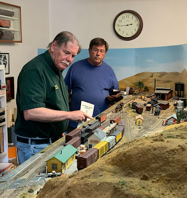
On Saturday, Michael and Adam paired off to begin work at Shumala. The photo below shows them in the midst of the switching, with Adam at right, holding the waybills, evidently the conductor at this point.

Meanwhile, at Ballard, Steve (at left) was the conductor, with David the engineer at this point. They were very meticulous in getting all the switching done correctly.

On Sunday, as usually happens, the same crew patterns were seen. The photo below shows Richard Brennan at left, wearing the conceptual conductor’s hat, and Jeff Allen behind him, holding the throttle for the switch engine at Shumala.

The other crew at Ballard at that point was John Sutkus, conducting at left, and his engineer, Dan Miller. Dan is a relative novice at this kind of operation, but allowed himself to be persuaded to take a try at conducting when these two took their turn at Shumala. He took it one problem at a time, and got the work done in a creditable amount of time!

Crews had fun both days, and obviously were enjoying themselves, despite that one bit of bad track leading to Santa Rosalia. I tried to remember that “big picture” and not succumb to Host Flaw Hysteria, in which the layout owner assumes small problems overwhelm large successes, which luckily is hardly ever true.

Tony Thompson

Sunday, June 23, 2024

My engine servicing facilities

My layout of a fictitious Southern Pacific branch line was designed to have, as was SP practice, an engine terminal for the branch power. I have posted about my engine servicing facilities at the town of Shumala from the earliest days of this blog. For a look at those facilities in a fairly primitive state, see this post: https://modelingthesp.blogspot.com/2011/04/modeling-engine-terminal.html .

A few years later, I had built the excellent Banta Modelworks kit for the Port Costa SP roundhouse to go with my Diamond Scale turntable, and had added a caboose servicing building. I posted an update about the facilities to describe the changes; see: https://modelingthesp.blogspot.com/2016/01/shumala-engine-terminal-update.html

I also wrote an article for Model Railroad Hobbyist about engine servicing, which was in the issue for August 2017; that issue is still available to read on line or download, for free, at www.mrhmag.com . Many of my engine service details are shown in up-close views in that article.

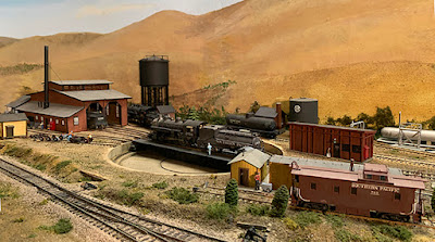
Then two years ago, when I had increased the detailing around the fuel and water columns of the service area, and added a scratchbuilt sand house and refined other details, I posted another update (it’s available at: https://modelingthesp.blogspot.com/2022/01/modeling-engine-servicing.html ). Here’s a view looking across the turntable toward the roundhouse, with the caboose service track in the foreground.

One relatively new feature in these facilities is a storage tank for diesel fuel. Since a diesel switcher is normally used at Shumala, this would be expected. I’ve now added it. It’s the silver tank shown below, just to the left of the sand house (the turntable pit is in the foreground). The large black tank is for steam locomotive Bunker C oil. In front of the tank are duckboards (see: https://modelingthesp.blogspot.com/2015/08/duckboards.html ).

Some time back I added a kind of “mini-scene” on a stub track off the turntable, to illustrate changing out a wheelset in a freight truck. This was part of another Model Railroad Hobbyist article about prototype trucks and wheels, in September 2016; this one too is still available for free.

In the view below, the scene shows a new wheelset being rolled into position to be placed in the truck. The removed wheelsets, with shiny wheel treads, are already moved out of the way. In the left background are shown a couple of truck bolsters and a stack of side frames (note the prototypical small kingpin center holes in the bolsters). This was set up temporarily, to photograph for the article, but I liked it and have left it in place.

Lastly, the track that you see just above the wheelset scene (above) is a track that serves the machine shop on the back of the roundhouse (see: https://modelingthesp.blogspot.com/2016/03/a-shop-track-for-shumala.html ). This allows me to set up varying scenes of parts deliveries to the roundhouse; machinery deliveries to the shop; inbound or outbound loads of wheels; and other interesting scenes. 

Here’s a load of new wheels arriving in a gondola, presumably for the roundhouse machine shop to complete wheel tread contours and press onto axles.

Another possibility (to choose just one alternative for illustration) is unloading something like machine tools from a flat car, at the machine shop loading dock. That’s shown below, and as with the scenes shown above, is readily changed. I originally tried to show a tarpaulin partly off one of the machines, but couldn’t make it look right to my eyes. (You can click on the image to enlarge it.)

All in all, I feel like my engine terminal facilities are complete at this point, and they serve what is needed as I wanted them to do.

Tony Thompson

Thursday, June 20, 2024

The Timken promotional freight car(s)

Sometime in the mid-1940s, the Timken Roller Bearing Company purchased one or more freight cars, applied roller-bearing trucks, and painted it (or them) in vivid paint scheme(s). One report is that these cars were exhibited at one or more railroad fairs, others that they were moved around the country on various railroads for publicity purposes. 

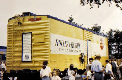
Certainly one of the cars was exhibited at the Chicago Railroad Fair of 1948–49. Below is a photo of the car at that fair, from an internet site (you can visit it at: https://www.railarchive.net/rrfair/rrfair4869.htm ).

It is hard to get much more specific than what you read above. About 20 years ago, Bob Weston wrote, on one of the on-line forums, this comment: “The Timken Roller Bearing Company painted several freight cars in color schemes to promote its products. I've seen pictures of two boxcars in different schemes. Or was it one boxcar in two schemes? One car was done in conjunction with the Akron, Canton & Youngstown RR, I believe it was numbered 600. There was also a gondola painted in red and white and blue. I’ve also heard that a tank car may have been painted for the Timken Co.”

The photo above proves that there was at least one car, a 1937-AAR design box car built for Timken in a one-car order by AC&F. It was evidently originally painted green, but soon became yellow with the wide white stripe and Timken logo. It was then numbered TRBX (for Timken Roller Bearings) 88, but one source references a TRBX 81; or maybe there were two cars. The car which became AC&Y 600 was transferred after 1950 but before 1953. (The Timken plant was in Canton, Ohio.)

Back in the days of Athearn metal car kits, there was a model of a Timken box car, though Athearn first advertised the version with red instead of yellow sides. Note in the page below, from the 1948 catalog, that Athearn mentions “You’ve seen this car in all the national magazines – now have it on your layout.” (Catalog page from the “HO Seeker” site: https://hoseeker.net/AthearnBrochuresAds/brochure1948pg1.jpg ) The car number appears to be 88.

There is evidence that the red scheme was at least something promoted by Timken, whether or not it was applied to an actual car; below is a 1947 ad from Railway Age (maybe one of the “national magazines” mentioned by Athearn). These cars have three-digit numbers. Note that the white stripe is lower in this artwork than in the Athearn model photo above.

Athearn’s red scheme car was joined later by an Athearn metal model in the yellow scheme, as you see in the Internet photo below, also numbered TRBX 88. The roof is supposed to be black.

By the 1953 catalog, Athearn offered not only the yellow and red schemes, but also a silver Timken box car scheme. That was included in their 1954 catalog as well, but by 1957 all Timken cars were absent. Here’s an internet photo of an Athearn model in the silver scheme:

Athearn also did one of their 12,500-gallon metal tank cars in the yellow scheme, and I have one of them. These were never pictured in an Athearn catalog, but they were listed in the catalogs from 1948 through 1954, inclusive. In 1957 Athearn had dropped them from the listing. Like all the Athearn metal tank cars, they have nice two-rung sill steps and free-standing tank hold-downs.

These Athearn metal cars are from the modeling era when imaginary paint schemes were still rare, so I give them some credence. 

It is interesting that on the web one can find a couple of paintings by a prolific artist named John F. Gould. These might have been commissioned by Timken. They show dramatic views of Timken rolling stock, though I have no idea which or how many cars really got painted this way. Below is one example (the fifth car back is a tank car). To see the variety of Gould’s work, you can visit https://johngouldart.com/gallery/ .

So I can’t find firm information about how many or which kinds of freight cars may really have worn these Timken schemes, nor how long they lasted. I only operate my Timken tank car occasionally, and only in through trains. But I’d like to know more.

Tony Thompson

Monday, June 17, 2024

Bay Area Prototype Modelers, 2024

Once again, as June rolls around, we arrive at the annual Bay Area Prototype Modelers (BAPM) meet, held at the traditional location in Richmond, California. Outside the meeting room, arrivals were greeted by the traditional banner with the BAPM logo:

Like all RPM (Railroad Prototype Modelers) meets, it’s a major feature that you get to meet and greet lots of fellow modelers of a mostly serious hobby attitude. And a special treat is to browse the room full of tables that are loaded with models, and not only to appreciate the model work but also to meet the modelers. 

I’ll mention a few highlights. One young modeler whose work I liked was Colin Minekheim. One of his models was a fine reproduction of a prototype photo in my book, “Box Cars,” Volume 4 in the series, Southern Pacific Freight Cars (revised edition, Signature Press, 2014). That Dick Kuelbs photo is found on page 303. The car shown there is a former “Overnight” car, returned to freight service and renumbered with a boxcar red patch. His model very nicely reproduces that photo, even with the same car number.

He also displayed a neat job of modeling one of the four Alco Century 628 demonstrators that SP purchased and simply “patched” with road name and number, right over Alco’s gold and black demonstrator paint scheme, and put in service. Obviously it’s been hard at work!

Another nice job of a process I always admire, reproducing graffiti on prototype cars, was done by Scott Kelley-Clement. Here is the prototype photo he was guided by:

And here is the model he created, using a Rapido HO model of a Pacific Car & Foundry SP Class B-100-40, and hand-painting the graffiti:

Also of interest to me was a really nice job of showing age in a galvanized roof, a model by Tom Bacarella. My photo, below, barely does justice to how good this looked.

As I always do, I brought a complete HO scale train, headed by a Class C-9 Consolidation and trailed by an SP steel caboose. A number of the cars were the same ones I had shown in 2022 (for which, see this post: https://modelingthesp.blogspot.com/2022/07/my-display-train-at-bapm-2022.html ), so I will only show the newer ones. 

I included a well-used PFE reefer, something I model in moderation but do include in my fleet of PFE cars. The foreground description explains it.

Another car in the train was a recent tank car project, which I reported in a blog post earlier this year (my full description concludes at this link: https://modelingthesp.blogspot.com/2024/02/modeling-sp-class-o-50-9-tank-car.html ). Again, the description is in the foreground.'

In closing, I’ll mention again the very real camaraderie of these meetings, along with the pleasure of seeing completed and in-progress models. It’s not only fun, you can learn a few things too.

Tony Thompson

Friday, June 14, 2024

Background for my layout ice deck

A visitor to my layout recently asked about the ice deck I have modeled, and I explained a few aspects of it. It occurred to me that others might also be interested in the topic, thus this post.

Like nearly all layout owners, I have limited space for an ice deck. It’s rare, when visiting a layout, to see even a six-car deck (in HO scale, that’s already three feet long), though the prototype often had decks of 15 or 20 cars. Mainline ice decks in some cases were 110 cars long, the size of a reefer block on the SP and UP in ice reefer days. 

My deck is just two cars long. Is this realistic? Absolutely. In Chapter 13 of the PFE book (Pacific Fruit Express, 2nd edition, Signature Press, 2000) are listed all the ice decks along PFE territory (SP, UP, and WP). There are a number of small ones, such as the two-car Modesto deck on the Tidewater Southern (a WP subsidiary). 

That TS facility was owned by Union Ice Company, and was contracted with PFE for service. This kind of deck supplemented the much larger, nearby deck at Modesto on the SP, 29 cars long and capable of icing from both sides of the deck.

In building my small facility, I began with the idea that 300-pound ice blocks for icing reefers would most likely have to be shipped in. A small facility making consumer ice would rarely be able to produce such big blocks, and indeed, ice delivery was a common arrangement for small decks. Thus I only needed an ice storage building, not a giant ice manufacturing plant.

I built a simple structure using Evergreen shiplap siding, reinforcing the inside corners with Plastruct angles and the walls with square styrene tubing, as you see below. Outside corners were given scale 1 x 6-inch trim boards. I added five doors: a man door on each end, a pair of ice loading doors, and an ice delivery door for the ice deck, along with an office window.

In the photo below, with the removable roof off, you can see the construction, along with the two doors on the ice-deck end, and the ice loading door on the side, with its buffer timber underneath.

For the ice deck itself, I began with the PFE drawing in Chapter 13 of the PFE book. My ice deck would be a privately owned deck, so wouldn’t match the PFE standard (certainly no roof), but it gives dimensions and some idea about lumber sizes.

The drawing above is only a cross-section, and doesn’t show longitudinal bracing. For that, I relied on a photo of a small PFE deck at Spokane, Washington, which unlike the drawing above, didn’t have a center post (PFE photo, CSRM). It was an 8-car deck, and had PFE’s usual drop-down aprons, though those were uncommon on private decks.

With these considerations, I was able to build a deck from pre-stained stripwood, using a fixture to asemble each bent to ensure they were all the same. I added a stairway at the rear for workmen to access the deck. The door for delivery of reefer ice is on this side of the building.

Looking down on the deck, you can see the steel sliding tray used to slide ice blocks along the deck, from the ice house to where they are needed. Here an ice bridge is in use, to slide ice chunks (chopped from the original blocks) over to the further ice hatch. I included this photo. along with a discussion of the tools the men are using, in a recent blog post (see it at: https://modelingthesp.blogspot.com/2024/04/my-latest-column-in-mrh.html ).

Though my layout’s ice deck is small, it is realistic for the needs of the (fictitious) SP branch I model. I have tried to include prototypical details so this ice facility believably provides refrigeration for outbound reefer loads on my layout.

Tony Thompson

Tuesday, June 11, 2024

The role of “foreign” cars in your fleet

Modelers often choose to model a prototype railroad that they particularly like, and then populate their freight car fleet with lots of cars decorated for that railroad. That’s perfectly all right, as far as it goes, because most railroads would in fact have a lot of their own cars on their own rails. But what about “foreign” cars, meaning cars owned by other than the home railroad? 

One issue is whether one should choose any old foreign railroads one happens to like,  or whether there are prototype patterns that ought to be modeled. Of course, like practically everything in model railroading, you can care or not care about the prototype. Here I’m addressing those who want to care.

If one wants to mirror prototype practice, one basic approach to this problem is called the Gilbert-Nelson approach, based on ideas first developed by Tim Gilbert and Dave Nelson. They had looked at extensive prototype information, particularly conductor’s time books, and realized that there was a pattern: many cars present in trains were numerically in proportion to the size of the owning road’s fleet, regardless of where in the country the data originated.

This means that a good first approximation to the choices of foreign road cars, and their relative abundance on the layout, is simply the size of foreign road car fleets. I show below a graph I’ve presented in several talks. These data are for 1950, and are modified from total car fleets by removal of ore cars, hopper cars, and ballast cars (as less frequent interchange cars in most part of the country). Especially as an SP modeler, the likelihood of coal-road hopper cars on my layout is pretty small and I neglect it. I have also separated out the refrigerator cars from Santa Fe, SP and UP. 

Of course, as Gilbert and Nelson fully recognized, this can only be true of free-running cars like box cars, flat cars and gondolas which are not specially equipped, and is likely true only on main lines. A coal branch, for example, will obviously be quite different. Still, this graph certainly identifies the major players.

My response to these major railroad ownerships is that I try in setting up operating sessions to make sure that there are always one or more cars from PRR and NYC present, and often B&O and Milwaukee also. Accordingly, when one sees something like the photo below, a gondola emptied of its cargo at the team track in East Shumala on my layout, there is a reason.

What about Santa Fe? As a strong competitor and rival of SP, any empty Santa Fe car would be directed promptly by SP crews back to Santa Fe at the nearest connection (for my layout, Los Angeles). But of course inbound Santa Fe cars, loaded all over the nation, certainly would appear on the SP, and I do include them in an inbound role in most sessions.

You may notice that Union Pacific is down at 12th in fleet size in the graph above. Because SP and UP were locked into a partnership on the Overland Route through Ogden, Utah, this might seem like a major source of UP cars on SP rails. But UP in those days was predominantly a bridge route, with relatively little originated traffic, so UP cars really would act like other faraway roads.

Are there other factors that come into play? One factor is whether the home road (SP in my case) had friendly or unfriendly relations with the railroads it interchanged with. It’s known that SP had friendly interchange relations with NP, RI and IC (at far ends of the system: Portland, Tucumcari, and New Orleans) in addition to the UP relationship mentioned above. 

The other important question to consider is the proportion of home road cars, vs. foreign cars. This does not seem to have a universal answer, and Gilbert-Nelson found different proportions in different places. 

There is an old rule of thumb, that home road cars may be a third to a half of all cars. I explored that point with some 1948–1952 time books (see, for example: http://modelingthesp.blogspot.com/2011/03/modeling-freight-traffic-coast-line_11.html ). What I found was in fact about a third for SP cars in California, and that’s supported also by photos. I have operated my layout on that basis, roughly one third home-road cars.

Needless to say, there is no reason for slavish adherence to any specific part of these ideas. There is much evidence that car identities could vary wildly from day to day in many trains or yards. But making an attempt to maintain an overall pattern on a layout makes sense to me, as a gesture to realistic railroad modeling.

Some discussion of this issue, predating Gilbert-Nelson, can be found in an article I published some time ago, copies of which can be obtained from the NMRA library. It is the source of data for the graph shown at the top of this post. If you’re interested, here’s the citation:

Anthony Thompson, “Railroad Freight Car Fleets," in Symposium on Railroad History, published by A.C. Kalmbach Memorial Library, NMRA, Chattanooga, TN, 1990, pp. 27–44.

Tony Thompson

Saturday, June 8, 2024

Modeling SP passenger cars, Part 20

As in the recent posts in this series, I continue in this post to address lightweight passenger cars of the Southern Pacific. (Finding earlier posts in the series is easily accomplished by using “modeling SP passenger” as the search term in the search box at right.) In the immediately preceding post, no. 19, I was discussing trucks for these cars (see that post at: https://modelingthesp.blogspot.com/2024/06/modeling-sp-passenger-cars-part-19.html ). 

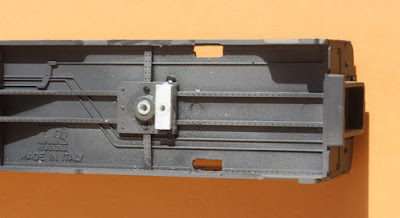
I mentioned in that previous post that I’d like to use some of the Central Valley no. 139 trucks that I have (trucks rebuilt with Northwest Short Line wheelsets). These trucks have their bolster hole in the truck center, as do most trucks. But the Rivarossi trucks that come with the lightweight cars most definitely do not have centered attachment and holes. The photo below shows that hole well to the right of center.

I have shown in an earlier post (no. 10 in this series) that this truck design, with the sprung “coupler arm” culminating in a horn-hook coupler, can be modified to accept a Kadee coupler in its own box (see it at: https://modelingthesp.blogspot.com/2021/04/modeling-sp-passsenger-cars-part-10.html ). If that is done, of course, the truck remains in use and its off-center attachment is not a problem.

But the Central Valley no. 139 trucks do have a center bolster hole. Thus the Rivarossi truck attachment location, shown in white below, is off center in the car body truck space (by about 1.5 scale feet) and has to be replaced. In addition, the molded “alignment pins” as I call them, have to be removed. These are quite evident on either side of the bolster in the image below.

So a bolster pad has to be created that is centered in the car body truck space. I experimented with various sizes of styrene strip, and found that the height of the cylindrical center of the bolster, shown above, is about 8 scale inches. I built up a bolster pad of that thickness, attached using styrene cement, as shown below. This was done because attaching the Central Valley trucks to the off-center bolster had already shown that coupler height was going to be correct.

You can see in the photo above that the new bolster pad was drilled to accept 1/8-inch styrene tube, which in turn was then tapped 2-56 for truck screws. (Note also that the “alignment pins” have been removed.)

Next I had to address coupler placement. The two lengthwise members (sills?) molded on the Rivarossi underbody are lined with rivets (as is visible above), which I removed near the car end, and then glued on a pad of 0.030-inch thickness styrene. I then mounted Kadee couplers in their own boxes.

The completion of these modifications allowed the view above (the car is a 10-6). Note that the trucks are now centered where they should be, and coupler knuckles are located just outside the outer edge of where the diaphragm face plate will be. This means that cars can be nearly in contact during operation.

My last task on this car is to add the diaphragm face plate and stabilizer bars to the Rivarossi “surround” on the end door. (See my previous post about doing this: https://modelingthesp.blogspot.com/2023/09/modeling-sp-passenger-cars-part-17.html ). When it’s all done, the diaphragm area will look like this (another 10-6):

I am pleased with my success in adding some of the Central Valley trucks to these cars, both because they add weight and because they separate the coupler from the truck, something occasionally troublesome with retaining the Rivarossi “Talgo” coupler arrangement.

Tony Thompson

Wednesday, June 5, 2024

Modeling “billboard” refrigerator cars

Modelers are generally familiar with the dramatic, even extravagant, paint schemes created for leased refrigerator cars up to the middle 1930s. They were effectively outlawed by the ICC in 1934 (which took effect in 1937), in a widely misunderstood ruling. And there is an entire book devoted to this topic, containing more than 440 photos, from noted authors Richard H. Hendrickson and Edward S. Kaminski: Billboard Refrigerator Cars (Signature Press, 2008). Having acted as editor for this book and written its foreword, I know its contents well.

Below is the dust jacket of this book, containing two photos colorized in the 1930s and thus among the very few paint schemes for which we can document color from contemporary sources.  

What does this mean for modelers? I want to cover three points. First, a brief summary of what the ICC actually did in 1934. Second, a few words about what this means for paint schemes in subsequent years. And finally, what modelers need to know about these paint schemes.

The book mentioned above contains, as an appendix, a summary from Railway Age magazine of the problems addressed by the ICC decision, and what the ICC actually did. It’s a useful summary because it’s far shorter than the voluminous ICC report, though the ICC language is extensively quoted. 

The core of the problem considered by the ICC lay in the fact that owners of refrigerator cars were remunerated for their use, not by per diem payments as was the case for most freight cars, but by a payment per mile moved, loaded or empty. This had led to abuse by leasing companies, encouraging excessive empty mileage and in effect paying rebates to lessees who concocted ways to generate that mileage (at the expense of railroads). These practices were then forbidden.

Modelers have long been interested in what was a detail of the ICC ruling, the banning of car-side advertising. The advertising on the “billboard” cars was furnished free by the lessors, and thereby furnished something of value to lessees, which was not available to shippers using railroad-furnished cars. The initial ICC decision prohibited advertisements of shippers, consignees, or products on leased cars, effective January 1, 1937. 

But before long it was recognized that cars exclusively leased to a single shipper could reasonably carry the shipper’s name and emblem, provided they did not advertise specific products. The same was true for shipper-owned cars, such as the meat-packing company car fleets. Gradually other aspects of the advertising prohibition were relaxed also. Below is my model of a 1948 Swift reefer scheme, spotted at the wholesale grocer’s warehouse on my layout.

What about modeling these cars? Most of the most dramatic billboard schemes date from the 1920s, so modelers of earlier eras have distinctly less opportunity to use these paint schemes. And after January 1, 1937, the flamboyant original schemes were surely gone, particularly those advertising specific products such as ham or cheese. As mentioned, some lessees did gradually introduce more colorful cars in later years. 

There is also the problem that this era predates commercial color photography, so color information for the great majority of the schemes does not exist. But as shown in an appendix to the billboard reefer book (citation in first paragraph at the top of this post), the Red Ball car sides, originating in the late 1930s, certainly are likely to be close to actual colors, if not precise matches. If you happen to model the pre-1937 era, some of these may work for you. I show one page of these below, from a 1950s Red Ball catalog (reproduced with permission).

What can a post-1937 modeler do, who likes these schemes? That depends on how far past 1937 you are modeling. Certainly for the first few years after 1937, that modeler is out of luck, not only because of the ICC prohibition, but because most lessors and lessees were really gun-shy and didn’t want to challenge the prohibition in any way. Leased cars were really plain for several years.

But as you move farther forward from, say, World War II, more and more reefers carried lessee’s names and logos. If you love the pre-1937 schemes, though, you’re still limited, because re-introduced meat company and other schemes simply differed. The pre-1937 schemes reflect their original era’s advertising approach, and wouldn’t be brought back in any case. I remember cringing a bit at a late 1950s layout that had one of the Berkshire Ham and Bacon cars (see above) in a freight train. Not likely.

But because the simplest, relatively plain schemes were close to permissible, some did continue, or survived in modestly modified form, so a modeler could choose any historic scheme that was plain enough to have plausibly continued. One of them is the Pacific Egg Producers scheme (the organization morphed into today’s Pacific Egg & Poultry Association); this scheme is shown in the Hendrickson and Kaminski book. I scratchbuilt a wood body for a pair of Red Ball sides, and added detail parts from several sources. This car, shown being switched at Shumala, does operate from time to time on my layout.

There is no question that the “billboard era” cars were visually striking, and having an itch to model some of the flamboyant cars is understandable. I have a couple of the spectacular-scheme cars myself, but if you see them at all, they will be found in my display case, not on the layout. Of course, your mileage may vary.

Tony Thompson

Sunday, June 2, 2024

Modeling SP passenger cars, Part 19

In recent parts of this series, I described work on creating Southern Pacific lightweight sleeping cars. Most of that work was collected in my article in Model Railroad Hobbyist, in the issue for October 2023. The more dramatic projects were those that used sides from Brass Car Sides to create two car types: 13 double bedroom (13 DB) cars, and 4 double bedroom-4 compartment-2 drawing room (4-4-2) cars.
The work on those cars can be well understood in this post: https://modelingthesp.blogspot.com/2023/04/modeling-sp-passenger-cars-part-14.html , followed by the nearly completed cars shown here: https://modelingthesp.blogspot.com/2023/10/modeling-sp-passenger-cars-part-18.html . Below is a view of my 4-4-2 car, shown bringing up the rear of a train passing Shumala on my layout.

But work is not complete on some of the other cars I’m working on. As I mentioned in passing in a couple of previous posts, the stock Rivarossi bodies are rather light when unmodified. Addition of brass car sides is a real help with weight, but cars not so modified need additional weight. I have used, as I often do, steel nuts glued inside the car with canopy glue. For passenger cars, I use 1/2-13 nuts, which I paint flat black to minimize their visibility inside the car.

And while one of these model cars has the roof temporarily removed and the inside accessible, I also need to add view blocks. As I showed in the MRH article, the great majority of modern lightweight cars had all enclosed accommodations, which in turn means that unless someone had opened a door into one of the rooms, there was no way to see through the car. This is certainly clear for the stock Rivarossi lightweight sleeping car, the 10 roomette-6 double bedroom (10-6) car.

At one time, Rivarossi did market an one-piece, molded interior for these cars. It’s a nice idea, but unfortunately they chose to model this interior with all room doors open. Here you see it in my already repainted and lettered SP 9051, a Lark 10-6 car.

To make new view blocks, I simply cut rectangles of 0.010-inch styrene sheet to fit, and painted both sides with one of the SP passenger interior colors. For the car shown above, I chose a pale gray, Tamiya “Corsa Gray,” PS-32, a somewhat bluish light gray. I installed the blocks with canopy glue.

This is an adaptation of my view block ideas to the Rivarossi molded interior. As I showed earlier, for example in the MRH article mentioned in the first paragraph, above, without a molded interior, a full-length styrene strip serves nicely as a view block. The car below is the 4-4-2 car I created, an all-room car, and the view block is painted a cream color.

Another way to add weight to these cars is to replace the very light plastic Rivarossi 4-wheel trucks. I have some of the Central Valley No. 139 trucks rebuilt by Brass Car Sides with Northwest Short Line wheelsets, which do add weight. They also require body-mounting the couplers, but I have wide enough curves on my layout that this will work. 

An aside about trucks for these lightweight cars: Pat Wider’s excellent article in Railway Prototype Cyclopedia, Volume 6 (2001), entitled “Lightweight Passenger Car Trucks,” pages 76–104, is a good introduction to these trucks and also tabulates actual trucks on specific cars of many railroads. 

An even better article, that includes information on model trucks, is W. Gordon Anderson’s “Passenger Trucks of the Lightweight Era: Part 1,” in Mainline Modeler, Vol. 3, January-February 1982, pages 72–83. Below are Anderson’s photos of two model trucks. At left is the Rivarossi truck, and at right is the Central Valley lightweight No. 139 truck.

What prototype trucks do these models represent, and which ones do we want to represent? The postwar SP 10-6 cars had 41-ND-11 trucks, while many of the pre-war 13 DB and 4-4-2 cars had 41-HR trucks. (The Pullman truck code 41-N means 4 wheels, 1 bolster, and N = an 8'6" wheelbase; an “H” in the code indicates that all springs are coil springs.) 

The stock Rivarossi truck has a nearly 9-foot wheelbase but looks approximately like the Pullman 41-N; however it has a lower overall truck height, and roller bearing representations resembling no prototype. Below is a Pullman photo from Anderson’s collection, showing a 41-N truck.

On the other hand, the Central Valley truck is really a 41-E (the code E means it has an elliptical [leaf] bolster spring, instead of a snubber, while also having coil springs), though otherwise similar to the 41-N shown above, and like that truck, has an 8 ft. 6 in. wheelbase.

I believe the Central Valley truck is the right length and is close enough in overall appearance to be used on the SP cars I operate. I will return to their installation challenges in a future post.

Tony Thompson