Monday, March 29, 2021

“Vaccinate to Operate”

 The title above says it all (a phrase a friend used recently). Yes, like so many, I’ve been eagerly awaiting the situation where enough people would be vaccinated that we could break the long pandemic “outage” and have a layout operating session. This past weekend, on my layout, we got there. 

It was interesting to find how much was needed, after a year or so of not operating (except small sessions with my granddaughter). Getting ready was a bigger deal than I’m used to. Projects all over the layout needed to be completed; some unused track needed to be cleaned; locomotive wheels likewise; and literally all the rolling stock on the layout and staging had to be re-evaluated for the next session. Like I said, interesting . . .

One project was to move my small scrap yard from the back of the layout to the foreground. The dark colors of the scrap pile were just a distant smudge before. Now it can be seen for what it is, tucked between Corralitos Lane and Laguna Street.

This little industry was described in an April Fool’s Day post last year, which if you’re interested, you can read here: https://modelingthesp.blogspot.com/2020/04/adding-off-line-industry.html .

But here we are. After carefully reading the CDC guidelines for vaccinated adults, and discussing them with knowledgeable people to make sure I was reading them right, I invited my usual operators list, but making it clear the invitation was just for those who had been fully vaccinated. Dates were March 27 and 28. With full crews signed up for both days, we went ahead. 

It is hard to convey how much everyone enjoyed these sessions. It was great fun for me to prepare the sessions and help solve problems during them, and everyone who operated was just so pleased to finally have a chance to do again, something we all enjoy. 

The two crews the first day were as follows. First, Ed Slintak (left below) teamed with Richard Brennan. If you know Ed, you realize this is his pandemic beard. They are pictured as they started work at Ballard.

The second crew comprised Seth Neumann and Steve Van Meter, shown later as they took their turn to work at Ballard. Seth, seen below at left, is holding waybills, and Steve, who was engineer, holds an uncoupling pick. 

The next day the previous session was essentially repeated with a new crew. This time, we decided to pose for a group photo (my wife was good enough to take the snap). Below, from left, it’s me, Chuck, Hakkarinen, John Sutkus, and Jon Schmidt. We’re standing alongside Shumala on the layout.

We really did have fun, the crews and me both. What a pleasure to operate again, sans masks, etc. We were just to glad to start feeling that the light at the end of the tunnel really is daylight.

Tony Thompson

Friday, March 26, 2021

B&O covered hopper, Part 2

 In the previous post about this model, which represents B&O’s Class N-34 “wagon-top” covered hoppers, I showed the prototype and the mostly-completed model I had purchased, along with the first and probably most challenging step in completing the model: adding the sill steps. That post can be found at this link: https://modelingthesp.blogspot.com/2021/02/a-b-wagon-top-covered-hopper.html .

As I mentioned in that previous post, the model as I received it had a cast-resin running board attempting to depict a metal-grid running board. Partly because it was broken, and partly because nearly all the prototype cars kept their as-built wood running boards all their lives, I removed the remnants of that “grid” board from the model, resulting in this (in this photo, sill steps are not yet applied):

Next, I carefully cleaned up the roof running board supports so the running board would lie flat. Then I installed the kit’s “wood” running board parts with canopy glue.

To complete the running boards, I added corner grab irons with Tichy part 3028. With these, I don’t use modeler’s eye bolts at the corner, as they are way oversize for what the prototype looks like. Instead, I just insert a short length of wire at the corner. 

Second, I installed supports under the ends of the running boards with scale 1 x 3-inch styrene, and added a route card board above the left-hand truck on each side, using scale 2 x 6-inch styrene strip, all attached with canopy glue. (You can click on the image to enlarge it if you wish.)

Next I needed to address the missing locking bars. A complete arrangement here would not only involve the long locking bars parallel to the roof edge, but two hold-down bars on each hatch, and a handle bar on each side. I decided not to do all of that, as this is largely a main-line car that will be seen only in passing trains. Following the principal that there merely “should be something in that area,” I used plain brass wire for the long bar and handle.

Finally, I had to match the existing paint to touch up all these detail additions. What was a pretty reasonable match (perfection not necessary because I will be adding weathering and cement staining) was Model Master “Light Sea Gray,” FS36307 (a Federal Standard color). As you see below, color looks good overall, and now the sill steps are visible — when they were their original black, they were hard to see.

I’m still delighted with my bargain purchase of this West Shore Line model of a B&O wagon-top covered hopper, an interesting and distinctive prototype to include in my fleet. Adding more and better details just adds to the value, in my own estimation.

Tony Thompson

Tuesday, March 23, 2021

Freight car graffiti, Part 24: more autoracks

 This is another in my continuing series about the application of graffiti to freight cars for a layout set in 1999. To locate previous posts in the series, the simplest process is to use “freight car graffiti” as the search term in the search box at right. For the previous post about autorack cars, you can use this link: https://modelingthesp.blogspot.com/2021/01/freight-car-graffiti-part-22-autoracks.html .

To repeat a comment from that previous post, my observation of prototype autoracks shows that the graffiti are almost always of the kind that can be done fairly quickly, small pieces near the bottom of the car, and lots of tags or “throw-up” pieces (for background, see my article in Model Railroad Hobbyist, January 2020). An example prototype photo that I took is below.

In model form, these cars have complex side screens and are thus an interesting challenge to decal. Like the previous autorack models I showed, they are InterMountain products. The first model autorack I want to show is a Burlington Northern rack on a Trailer Train flat car, TTX 604393; it is shown below as I received it.

I applied a variety of decals here. On the left side of the car, I used decals from Blair Line set 2262 and from Microscale set 87-1536. After a coat of flat and weathering with acrylic washes, and adding a few tags, the left side looked like this: (You can click on the image to enlarge it if you wish.)

The right side of the car was done a little differently, using all Microscale decals, sets 1533 and 1536. Then again, a coat of flat finish was followed by acrylic wash weathering and a few tags, mostly with “Gelly Roll” fine-tip pens.

The other autorack in this pairing was a Santa Fe car, slightly different in that the rack rides on a Santa Fe flat car, ATSF 88428, unlike the practice on most railroads of using Trailer Train flat cars. 

I will again begin with the left side of this model. Here I used decals from Microscale set 87-1523, from Blair Line set 2262, and a T2 decal. The decals were given a coat of flat finish, followed by acrylic wash weathering, and a few additional tags with “Gelly Roll” pens. The car then looked this way: 

For the right side of this rack, I again applied T2, Blair Line (set 2263) and Microscale (set 1535) decals, and followed up with a coat of clear flat, weathering, and tagging.

These large models have been a challenge, both for sheer size and for the relatively rough surfaces of the side screens. But careful decal application can still be done, and I feel like the results give a good representation of what is seen on prototype autoracks.

Tony Thompson

Saturday, March 20, 2021

Making better roads, Part 4

 In the preceding post, I described some of the pavement markings applied to the roadway in my layout town of Ballard, that is named Bromela Road. As with previous work of this kind, I drew the information for the markings from the standards document, the Manual of Uniform Traffic Control Devices (MUTCD in its 1948 version, in use in my modeling year of 1953. My previous post can be seen at: https://modelingthesp.blogspot.com/2020/12/making-better-roads-part-3.html

But I have not described how to mark the railroad crossing of this road from the south side of the branchline main. That is the purpose of the present post. On that side of the crossing, the road essentially makes an almost right-angle turn at the tracks before crossing. In Part 2 of this series, I showed the drawing for the pavement crossing marking (that post is here: https://modelingthesp.blogspot.com/2020/09/makinag-better-roads-part-2.html ), and I repeat the drawing below. You can click on the image to enlarge it if you wish.

You may note in the drawing that it provides for tracks crossing the road at an angle. In my case, though, the angle is too sharp for the depicted markings. This possible situation is mentioned in the upper right corner of the image above. Here it is, enlarged:

Though I don’t have a crossing gate, it seemed clear that pavement bands can be other than parallel to the track, and my situation fits that well. For that reason, I decided to made the double stop lines perpendicular to the roadway center line, not parallel to the rails. 

(It’s perhaps worth repeating that the MUTCD, though certainly the national standard, was by no means required to be followed, and all states had a variety of variations in use. Gradually those variations have faded, and today they are uncommon, but in 1953 they were widespread. I gave some California examples in my article about railroad crossings and crossbucks, in Model Railroad Hobbyist or MRH, the issue for July 2020.)

Following my usual process, I used drafting tape to mask the road surface not to be painted, and used SP “Lettering Gray” for the markings, which I have done on other “darker” road surfaces. I only use white paint when the road is fairly light in color. This keeps the contrast consistent.


Another point regarding this sharp turn in Bromela Road is that it would often call for signs warning of the turn (the MUTCD makes clear that placement of these depends on the judgement of the highway engineer as to whether they are necessary). I decided to add them, as I already had the sign images in HO scale and could simply print out more of them. Here you see my warning sign, mounted on a styrene scale 4 x 4-inch post, with the crossbucks beyond it, nearer the crossing.

At the other side of the trackage in Ballard, there is another crossbuck, not previously shown, to which I added the name “Southern Pacific” vertically on the post, as SP did at more important crossings. I discussed this aspect of SP crossbucks in my MRH article, mentioned above. This location, right at the layout edge, is a good demonstration of why I built these HO scale crossbucks out of sturdy brass tubing and strip, as described in that MRH article.

This completes my Bromela Road crossing protection warnings and signs. I have one more interesting road crossing to describe, which I will take up in a future post. 

Tony Thompson

Wednesday, March 17, 2021

Operating loader-equipped box cars

 In a previous pair of posts, I described the prototype cars operated by General American-Evans under the GAEX reporting mark, primarily significant because they were equipped with the Evans Products Company’s “DF” loader equipment. These cars were leased, not sold, to railroads, in part to promote use and acceptance of the DF equipment by shippers and railroads. The second of those posts, describing a model GAEX car, is here: https://modelingthesp.blogspot.com/2021/02/gaex-box-cars-part-2-modeling.html

Many modelers may regard DF-equipped cars as something typical of the late 1950s and beyond, and certainly it’s true that such equipment greatly proliferated then. But the pioneering cars with such equipment were already in use by 1950, including the first GAEX cars built that year. And that wasn’t all.

There is information of interest on this topic in the Boston University MBA thesis by Burnis J. Sharp I cited in the first of these posts (see it at: https://modelingthesp.blogspot.com/2021/02/the-gaex-box-cars.html ); it includes data about the Western Pacific “Compartmentizer” cars (a Pullman-Standard loader design), which were the famous silver WP box cars with the giant orange feather. More on those in a moment.

Also noted in the thesis was the use by the Frank M. Wilson Company (a canning company in Stockton, California) of certain Southern Pacific box cars from Class B-50-22. All were equipped with the same DF equipment as the GAEX cars. Here are the four car numbers: 81516, 81683, 81716, 81894. Consulting an Official Railway Equipment Register (ORER) for 1953, all were classed as AAR XME, meaning loader equipment.

Here’s a view of some Evans DF equipment in use; the cargo is “Sacramento Brand” canned mixed fruit (SP photo). Canned goods were a large proportion of early cargoes in DF cars. The bulkhead visible above the cartons is a lattice style.

If one consults an ORER for 1953 — since I model 1953 — one finds that out of SP’s 500 original cars of Class B-50-22 built in 1941, 496 were still in service, and 151 of them were XME cars. (This was years before SP started identifying DF cars with those letters in a large yellow circle.)

Here is my Proto2000 model of an SP Class B-50-22, SP 81721, spotted for loading at the fish cannery in my layout town of Santa Rosalia. This would have been a prominent use of these cars in my modeling era, and of course readily supplied by Southern Pacific. The model is stock except for A-Line sill steps and an etched Morton running board.

I wrote an article for Railroad Model Craftsman, published in the issue for September 1994 (pages 56–59), about modeling the Western Pacific PS-1 box cars. Included in the three models I built was one of the silver cars with full-length orange feather. The model started out as an undecorated McKean kit with a 7-foot door added, along with new grab irons, hand brake, and running board.

The second car models the 1952–53 scheme applied to WP’s second batch of Compartmentizer cars, with a smaller orange feather. (Prototype paint and lettering information for these cars is contained in the article by John J. Ryczkowski, in Prototype Modeler, the March-April 1984 issue, pages 35–38.) Later in the 1950s, this paint scheme became standard for other WP box cars. 

The two cars shown above are much as they were in my 1994 magazine article. Since both are AAR class XME cars, they can logically be used for canned goods loading, more likely as inbound loads than as empties to be loaded. You can be sure that with only a handful of these cars in 1953, the WP made efforts to get empties home to reloaded by WP shippers.  Here is an example, spotted at Peerless Foods, the wholesale grocery warehouse in my layout town of Ballard.

I enjoy having specific cars like these for specific kinds of loading. In 1953, this kind of specialized equipment for general-service freight cars was in its infancy, but it’s interesting to be able to model it on my layout.

Tony Thompson

Sunday, March 14, 2021

Pennsy freight cars, Part 7: other cars

 In previous parts of this series, I have discussed the major types of Pennsylvania Railroad freight cars, namely box cars and gondolas. In each case, I have concentrated on the largest classes of the car type discussed (and PRR classes were generally bigger than anyone’s). You can find any of these prior posts by using the search box at right, with the search term “Pennsy freight cars.”

But there are other car types, and car classes, that may be worth including in a model PRR freight car fleet, even if you are not a Pennsy modeler. The PRR fleet was so large, that even its minor members often represent a class bigger than many railroads’ entire population of that car type. In the present post, I will present a few that I find interesting.

To choose an example somewhat at random, consider the X28 box car. Built to the same principles as the X29 but as an automobile car in the 1920s, they were taller (9 ft., 3 inches inside, compared to the X29’s 8 ft., 7 inches). They also had double doors when built, but were soon superseded by the X31 and X32 cars being built in the 1930s. They were then modified with single doors, becoming Class X28A

It’s true that in isolation, you could easily mistake one for an X29 (flat roof, plate ends . . . ). But in fact that measly difference in height does show up. If you put an X28A next to an X29, you can see the difference, here being switched at Nipomo Street in my layout town of Ballard. (The X28A at left is an Overland Models brass version.) You can click on the image to enlarge it if you wish.

Yes, the X28A wasn’t a big PRR class, a mere (!) 5000 cars — nearly all of which survived to be converted to single-door XM types. So this might be an interesting “minor” PRR car to include in a roster.

Another possibly interesting car to add to a PRR roster is the X26. Originally, this was a Pennsy USRA single-sheathed box car, of which the PRR received 9900 cars, by far the largest single allocation of this 50-ton box car. They did not long remain in original form, however, for in the 1930s PRR gave them new Hutchins roofs and steel doors.

That wasn’t the end of changes. From 1945 to 1949, PRR rebuilt 3500 of the cars with new steel sides and roofs, retaining, as did many USRA rebuilds, the original underframe and corrugated steel ends. Those rebuilds became Class X26c. You can see those features in my model of one of the X26c cars, PRR 106869, built from a Sunshine resin kit, and shown here being switched in my layout town of Shumala. In 1953, there were still more than 3400 cars of Class X26c in service.

Another car representative, in a way, of the PRR is the specialized heavy-industry car. In its heyday, the PRR served the heart of industrial America (at that time), and rostered numerous freight cars for that service. A model example is the F33 class well-hole flat car. I described building a model of this class from a Funaro & Camerlengo kit in a previous post (see it at: https://modelingthesp.blogspot.com/2021/03/another-simple-resin-kit-part-2.html ). Here is that model, weathered and in service, with chalk marks and a route card:

The floor of the well in these cars was ordinarily closed with removable boards, and they too were weathered a little differently from each other. Here’s a view of that:

A more humdrum car is the ordinary flat car. The PRR did not have a very big proportion of its fleet in the form of flat cars, but even so, a roster of the size of the PRR nevertheless did include a substantial number of flat cars. Among the really interesting ones was Class F22, a very short, high-capacity car, described by both AAR and PRR as a “gun flat” (naval guns) and classified by the AAR as Class FG. Shown below is such a car, PRR 435375, kitbashed by Richard Hendrickson from an Athearn flat car and at least one other model. It’s shown in a train on my layout’s SP Coast Division main line, with a transformer load.

The Pennsylvania was the owner of such a huge freight car fleet, easily the largest in the U.S. in the transition era, that even some of the (relatively) small car classes are worth including in a model car fleet. That’s the reason for showing the “minor” car classes shown in this post, and of course the reason I’ve chosen to model them.

Tony Thompson

Friday, March 12, 2021

Layout photography with a cell phone

 Now that a very large majority of people carry cell phones, and take a lot of their snapshots with those phones, it may be that more options are opened up than one immediately realizes. What I address in the present post is layout photography. My modeling is HO scale, and getting down to “eye level” (of an HO person), or getting into a layout area with lots of “impediments” (structures, say), can be a problem with a conventional SLR.

Now don’t get me wrong. I use my digital SLR all the time for model photography, and it has a lot of capabilities far beyond the simple cameras of cell phones. But it won’t fit in tight places, and the roughly two-inch diameter of the lenses I use make the center of that distance the “bottom” viewpoint for photography. However, below is something familiar to practically everyone: the back of a cell phone in a rubber case (it happens to be an iPhone).

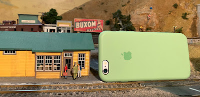
Here’s my point: the cell phone lens in this phone is less than 3/4-inch from the phone edge. Placed on the layout, this permits a viewpoint as low as, or even below, that of an HO scale person. To demonstrate, here is another cell phone at the Shumala depot on my layout. The lens center, as you can see, is a little above waist height of the HO figures. So actually you need to raise the cell phone, with lens downward like this, to achieve an “HO eye-level” view.

I have experimented with this kind of photography, and sometimes a quite nice photo is possible. One major disadvantage is depth of field, though with careful composition this can be used to advantage, as it can make less noticeable the areas you don’t want to show. Here is an example, from the engine terminal at Shumala:

The distant water tank doesn’t intrude too much into the main subject.

Another example is this shot of workmen preparing to ice a reefer at the Shumala ice deck. Nearly everything of interest is in focus. The cluster of stores in the right distance don’t distract.

But some shots really would require a through-focus series of images, assembled with photo-stacking software such as Helicon Focus. The image below, of the Santa Rosalia Local departing Ballard westward on my layout, does offer the drama of the head-on perspective, but a great deal of the image is out of focus.

As I mentioned, the cell phone’s size and slender shape allows it to be inserted into the layout at places not otherwise accessible by conventional SLR on a tripod. The example below is the unloading platform for high-pressure tank cars at the Pacific Chemical Repackaging facility in my layout town of Ballard. This viewing angle would not be accessible any other way.

For a final example, I have been experimenting with views that one might take if one were at the prototype equivalent scene, particularly ones with angles or perspectives not usual in model photography on layouts. The view below, of one of my SP Consolidations (a Key model), is an example. The fireman here, with a cigarette in his mouth, is a trademark of Al Massi, who tuned up the mechanism and installed DCC and sound.

These example show that there are a lot of possibilities for model photography with cell phones, beyond simply snapshots or overall grab portraits on layouts. It’s worth experimenting to find out what you can achieve.

Tony Thompson

Tuesday, March 9, 2021

Another family op

 My granddaughter was back in town last weekend, and I had set up an operating session for her. This time, we operated at my layout towns of Ballard and Santa Rosalia, and the plan was for her to do more of the conductor’s job, setting up the switching moves. Accordingly, she handled the waybills for all the cars.

But this time, I acted as “trainer” and helped her understand and plan the switching, instead of my wife Mary, the usual conductor in these sessions. When we started, the layout room was a little cool, and she had on her hoodie, as you see below, with me in the foreground (Mary took the photo).

The engineer is standing on a step-stool — she’s not really as tall as me. And you can see in the foreground that she has arranged some of the waybills on the J-strip along the fascia, organized in the pattern that made sense to her.

Things went well in the session, and we steadily got all the switching done. In fact, we did more than usual, even doing a pickup and spot over at Santa Rosalia and some other locations previously regarded as too complicated. And as the room warmed up, the hoodie came off. Here she is doing a run-around move.

Once we had done all the moves, and made sure the waybills had all been followed and the agent’s message obeyed, the train could be made up for departure, to run from Ballard back down the branch to the mainline interchange at Shumala. Here is the train at that point:

With the photograph above taken, the engineer could complete the job. And as you can see here, she always makes sure the headlight is lit.

As in every session, she was enthused about the chance to operate and as always, she was a very careful engineer, no excess speed at any time! I can think of some regular operators who I’d like to assign for training with her. 

It is of course a bonding experience for me and my granddaughter, operating on the layout, but she genuinely is interested in understanding what is called for in a session. She has learned to match up the waybills with the freight cars, and to plan ahead in switching to avoid repetitive moves. 

In fact, I would say that she has reached the point where I think she could hold her own in a session with adult operators — at least on the engineer job. She is still learning the planning needed when working as the conductor. That of course just gives us a goal for future sessions!

And speaking of adult operators, I  note that the CDC has released its guidelines for those who have been vaccinated for Covid-19 (including the post-second-shot waiting period), as follows: "People who are fully vaccinated may safely gather with small groups from other households without wearing masks or social distancing." I will be planning sessions on my layout in the fairly near future.

Tony Thompson

Saturday, March 6, 2021

Another simple resin kit, Part 2

In the past, I’ve posted a couple of descriptions of what’s needed to build resin kits that are not very complex, in hopes of encouraging those who are apprehensive about even trying one of these kits. My current project, Funaro & Camerlengo kit no. 6940 for a Pennsylvania well-hole flat car, was described in its beginning stages, along with prototype information, in the previous post (you can see it here: https://modelingthesp.blogspot.com/2021/01/another-simple-resin-kit.html ). 

In the previous post, I had only cleaned up the car body and added weight. Next I added the side and end grab irons as provided in the kit. Then came trucks. In the previous post, I showed the kit’s unpainted truck sideframes. Here is an assembled truck (I used recycled Kadee wheelsets) that has been painted black, and a truck frame ready to assemble. Word of caution: when assembling trucks, make sure that all six wheels touch the surface together, and the bolster is not canted or twisted.

Next, I needed to figure out my coupler and truck attachments. The kit directions recommend a trial fitting, a good idea to make sure everything works before adding any delicate detail. Below is the model, shown from below, with the brass screw heads evident for both coupler boxes and trucks. I chose to attach the trucks using screws offset from under the center axle. 

Now final details could be added: the sill steps and dual brake wheels (the prototype cars had an independent brake system on each truck). I was impressed with the resin sill steps, which accurately reproduce the prototype. But the resin brake wheels didn’t appeal. For flatcar hand brakes, I prefer to solder a brass brake wheel (Precision Scale) to a brass wire staff, and did so in this case. 

Next came painting. As with other Pennsylvania models, I used Tamiya red primer (“Oxide Red,” no. 87160), a color recommended by PRR modelers. The model below rests on my “interim truck support blocks” for painting (for a description, see: https://modelingthesp.blogspot.com/2014/11/interim-truck-support-blocks.html ).

To continue the theme of keeping this project simple, I used the “rattle-can” version of the Tamiya primer, and should repeat what I often mention, that the Tamiya cans show how well this kind of paint delivery works when well designed and produced.

Next came decals. The kit decals are quite complete, and as I normally do with F&C decals, I took the precaution of coating them with Microscale’s “Liquid Decal Film” before use. After decaling, I applied a coat of Tamiya Clear Flat, and painted the wood boards in the well with a “seasoned wood” color. I will develop more refinement on the boards after weathering the entire car — which I will do later.

I should repeat a comment from the first post, that these well cars (AAR type FW) are in a sense the opposite of depressed-center flat cars (FD). The load in an FD car is intended to be placed in the lower center area, while in an FW car, it cannot and must not rest in the center section. Loads have to be supported by frameworks resting on the car ends as you see in the photo below (Kenneth Rideout collection, courtesy Jim Seagrave; also included in the book, Pennsylvania Railroad Flat Cars by Gatwood and Buchan).

As I had intended and expected, this model was easy to build, with its one-piece body and few details to be added. About the only part of the kit requiring care is assembling the trucks. I hope this post gives a few “avoiders” of resin freight car models, some inspiration to give one a try. Start with something simple like this kit.

Tony Thompson

Wednesday, March 3, 2021

Workin’ on the fleet

 In a number of posts over several years, I have talked about maintaining a fleet of freight cars: my own fairly large fleet. What happens from time to time, in essence, is that cars that have been pulled off the layout for any kind of poor performance gradually accumulate until they are in the way. Then it’s time to work out the kinks and return them to service — if possible. The background here is what I call my “rookie test” for freight cars (see my description at: https://modelingthesp.blogspot.com/2018/07/the-rookie-test.html ).

The worst offenders are the cars that only misbehave occasionally. This makes you pull your hair out. But they still have to be fixed. The most common type in my experience is derailment due to misbehavior of the trucks. I postulate that occasionally a wheelset gets cocked or jammed in the sideframe, leading of course to derailment, but because this rarely happens, it’s hard to find. Simple solution: replace trucks. Here’s one of my misbehavers, shown right where it derailed

I replace lots of trucks nowadays. Back in the day, I always tried to use the kit trucks, sometimes with Kadee replacement wheelsets. Now I’m realizing that it can be the fault of the sideframes, and that replacing the truck can correct the problem. It can also be the wheelsets, if I used the kit ones, and nowadays I tend to replace with InterMountain wheelsets when they fit the sideframes.

Replacement of trucks can easily throw off the coupler height, as some manufacturers of model freight cars have designed models so that they have to be mated with the company’s own trucks. I always carefully check coupler height after truck change (for more about this, you can see my post on coupler maintenance, at: https://modelingthesp.blogspot.com/2019/10/maintaining-model-couplers.html ), and verify on the layout.

There are also problems that arise when a kit coupler arrangement is entirely replaced. Careful checking of the new coupler is essential. As always, I use the Kadee gauges, shown here with a Thomas Trains wine tank car from the 1950s:

Lastly, I have mentioned before that I also make “dynamic” checks of freight cars that have been repaired or upgraded with new couplers or trucks, deliberately pushing and pulling a group of suspect cars, often mixed with correct cars, through a sequence of turnouts (I described this process in an earlier post: https://modelingthesp.blogspot.com/2019/06/rolling-stock-upkeep.html ). The photo below shows such a test at Shumala on my layout. I continue to do that with cars that have had trucks replaced, since it was truck misbehavior that caused replacement in the first place.

A large fleet of model freight cars like mine simply requires maintenance, there’s no way around it. What works for me is to have an established procedure for this work, as I’ve described in the present and previous posts, and to stick to it whenever a batch of repairs/upgrades is being done.

Tony Thompson