It’s been a whole year since I had to report on any “challenges” with my layout trackwork, so no doubt Murphy’s Law suggests I am overdue to report again. And I have indeed been fighting my way through a problem or two. The main current challenge is the same track area and turnout as in the first of the posts on this topic, back in 2016, which you can read at this link: https://modelingthesp.blogspot.com/2016/09/trackwork-wars.html .
I have rigorously checked the track gauge throughout this Shinohara turnout, which is the lead to Track 7 at the back of my layout town of Ballard, so I believed that there was not a gauge problem. But steam locomotives of any wheelbase length whatever don’t play well with this turnout. I had long suspected that this turnout may not lie entirely in a single plane, as I noted in that previous post (see citation in previous paragraph), and I decided to borrow a friend’s tool for trackwork evaluation, a clear acrylic plastic “floor” with trucks. This has often been described in model magazines, and usually looks like this:
The turnout in question is at the far right of this photo.
Moving this vehicle through the offending turnout, slowly and carefully in both directions, immediately showed that there is indeed an out-of-plane problem, that is, that the entire turnout does not lie in a single plane, but has one side or the other elevated at different points. That means that if you could make yourself HO scale, lie on the track, and sight along the rails, this turnout would look a little like a potato chip, with first one side and then the other side elevated.
The best way to evaluate this in detail is to use a small level, which I proceeded to do. At first, I used the track car that you see above, laying the level across it as shown below, and this kind of works.
But the truck mounting on this track car is not sufficiently rigid to permit dependable and reproducible observations with the level. Instead, the level was used by itself, both on each line of track converging into the turnout, and across all rails of the entire turnout. This quickly showed the “potato chip” problem. I soon learned to make sure that the level is resting on, and only on, the particular pair of rails I was checking.
After brief reflection, I decided I should also re-check track gauge throughout the turnout area, just to make sure, and it was good that I did, since near the points the gauge was indeed a little wide. An additional track spike quickly fixed this. Here I am using my new NMRA Mark IVb gauge to verify conditions in the affected area.
With the information in hand about track levels, I used some styrene strip of various thicknesses, and progressively worked through the whole turnout to correct each local area and bring it close to the full level that I wanted. Here is this turnout (the background track is the lead to Jupiter Pump & Compressor). The bridge here is the pile trestle across Oso Flaco Creek (see my post at: https://modelingthesp.blogspot.com/2016/03/my-sp-pile-trestle-over-oso-flaco-creek.html ). The shims are white.
With the track shimmed and close overall to being in a single plane and in gauge, I decided to try and keep it that way. This turnout has had ballast in place, but not glued down, since I had been continuing to work on making this turnout perform better. But now, with things apparently corrected, or at least improved for the time being, I went ahead and used my regular method with dilute matte medium, dripped into ballast wetted with “wet water,” to tie everything down.
Once everything had dried thoroughly, I powered up the layout and ran a 2-8-0 back and forth through this area. This turnout certainly performed better than before, though still not perfect. And of course I may have to revisit this yet again, one of these days!
But the real test, as always, is an operating session. The just-concluded operating sessions over the previous weekend (you can read my account here: https://modelingthesp.blogspot.com/2019/11/more-operating-sessions.html ) did find this turnout performing pretty well, certainly without some of the problems of earlier days. In the absence of a perfect outcome, I am happy to accept an outcome that is significantly improved.
Tony Thompson
Saturday, November 16, 2019
Wednesday, November 13, 2019
More operating sessions
This last weekend, I hosted two more operating sessions on my layout, the second being the 50th session on the layout in its present form (there were also around two dozen sessions on the layout when it was in Pittsburgh, PA, sessions of varying degrees of formality).
This weekend I introduced a couple of new features that I have been wanting to incorporate. One of them was that the crew for the branch local train picked up their locomotive at the fuel and water spot by the roundhouse (I showed this in the new video of the layout; my post about it is here: https://modelingthesp.blogspot.com/2019/11/a-new-video-of-my-layout.html ). They then ran the train from Shumala to Ballard to begin work.
The other feature was an added mainline train during the session, this one an extra picking up empty ballast cars as part of a track maintenance campaign. I issued a Bulletin (shown below) to the crew at Shumala, and at the beginning of the session they found there were several empty ballast cars in the industrial spurs in town. (You can click on the image to enlarge it if you wish.)
The resulting train, behind a Consolidation and comprising entirely GS gondolas and ballast hoppers (most of them empty), was at least a little different than most mainline trains that operate in a typical session.
The first day we operated, the crew was four people, as is the normal number. They divided into two groups, one of which was Ed Slintak paired with Tom Swearingen, who you see from right to left below, starting work at Shumala. This was Tom’s first time operating on the layout, and he definitely enjoyed the experience.
The other crew of two began work at Ballard and Santa Rosalia, with the first run of the branch local train, but then worked at Shumala in the second half of the session. Below you see, from right to left, Ray Freeman and Ed Merrin planning their switching.
On the following day, Sunday, the 50th session, a new crew of four was present. This time the crews were Jim Radkey and John Sutkus, from right to left below, involved in their work at Ballard.
The other crew of two was Paul Chandler and Pat LaTorres, from right to left below at Shumala. I’m not sure why they look so puzzled. You can see the headlight of their switcher, just swinging off the main into the yard at Shumala.
This was a good pair of sessions, and did implement some additional features that I had wanted to add. That pleased me, of course, and hopefully added to the fun for the operators.
Tony Thompson
Sunday, November 10, 2019
A new video of my layout
Last August, the good folks from TSG Media, John Abatecola and his wife Cydney, visited my layout and shot a few hours of video, along with narration from me, and of course activities on the layout. This is part of their “Layout Tours” series, so it was my job to decide how I wanted to present the layout. I decided to treat it like an overview of an operating session, explaining some of the things I like to accomplish in a session.
I included a few words about how cars are moved in a session, and showed some trains, particularly, of course, the branchline local that does the work at Ballard and Santa Rosalia. I also tried to convey the complexity of the job at Shumala, with a mainline junction present. But most important to me was that I was given the chance to explain why my layout is the way it is, and what my goals were in building it.
I provide below a link to the YouTube version of this video. It has a couple of short ads scattered through it, which you can skip after a few seconds if you want (there is a “skip ad” button at lower right of the screen). I enjoyed watching it, and was particularly impressed to see the editing skill to boil down at least three hours of video into what you see (in a few segments, the switching was speeded up so you don’t watch the slow, repetitious bits).
https://youtu.be/RUfmRvun2_w
It was fun to plan how I wanted to show off different aspects of the layout, how best to explain my goals, and how I went about creating an operating scheme for the layout. And it was also fun to work with John and Cydney to create all the video that was recorded. I hope you enjoy watching it as much as I did.
Tony Thompson
Thursday, November 7, 2019
Brief update on armor modeling
Over the last year, I have posted a whole series of descriptions of HO scale modeling of armored fighting vehicles or AFVs, in connection with upgrading the old Roco model of a U.S. Army 100-ton flat car. Those cars were built to carry heavy AFVs, and were equipped with Buckeye trucks. I won’t list all the links here, though nearly all of them include the series title, “Roco flat car,” which if used as a search term in the search box at right, will find them all quickly. The most recent of the posts about armor and other loads for this flat car is this one: https://modelingthesp.blogspot.com/2019/10/roco-flat-car-part-10-still-more-loads.html .
One thing I included in those posts was references to a variety of published resources about AFV appearance, design and history. Recently I received an email comment that the publications I referenced were all more than 20 years old, and asking if there were more recent resources. I had cited the ones I felt were most informative, but yes, there are more sources. One is from prolific military history author Michael Green, whose most relevant book is shown below.
This was published by Osprey in 2014, and remains readily available in both hard cover and paperback, along with e-book versions, and can be purchased used from on-line sellers. It’s a 376-page book and is lavishly illustrated.
Another book I found interesting delves into the design and performance of tank destroyers, like the M36 model of mine that I depicted in this post: https://modelingthesp.blogspot.com/2019/10/roco-flat-car-part-9-more-armor-loads.html . First published in 2004 in both hardback and paperback, The Tank Killers by Harry Yeide is currently available in a modified edition published in 2018. The cover is shown below.
This is a 5 x 8-inch paperback of 292 pages (Casemate Publishers, Philadelphia and Oxford) and contains a great deal of interesting information, along with very thorough documentation (and footnotes).
(As it happens, I picked up this signed copy at Foyles in London, though the seriously quirky and funky Foyles premises of the past have now been replaced with a more modern bookstore building a few doors away, still on Charing Cross Road — and still of remarkable size.)
Both these publications, like the ones I’ve cited in previous posts on this topic, provide the most vital of all information for modeling: prototype appearance and time-line for when certain features were added or removed. However good a model starting point, such as a commercial model, the only way to make sure it’s right, or if not, to make it right, is to have the relevant information.
I think modelers often fail to recognize how much rich information lurks in the world around us, especially conveniently on the internet (where, as the saying goes, Google is definitely your friend) and in many other resources such as published books and magazines.Try and think where all your desired information might be located, and be patient in your search(es). I’ll bet you find more than you expected.
Tony Thompson
Monday, November 4, 2019
Trackside details, Part 2: physical
In an earlier post, I summarized several past projects on trackside details, consisting in particular of signage for my layout. There were a variety of these, all shown with links to details on the individual projects (see that post at: https://modelingthesp.blogspot.com/2019/10/trackside-details-signage.html ). In the present post, I want to turn to physical trackside details.
An important and visible trackside detail is a railroad structure such as tool houses, handcar sheds, or section houses. I have two section houses on my layout, and two tool house/handcar shed buildings, and may try to add one more tool shed (if I can fit it in).
I showed a section house in my post about details near the mainline tunnel on my layout (the post cited in the first paragraph). Another one was built to conceal a switch machine, as I have shown (see that project at this link: https://modelingthesp.blogspot.com/2014/03/constructing-section-buildings-part-1.html ). One of my tool houses is in Ballard, and is shown below. It’s a Rix “Pikestuff” kit.
Note the phone booth to the left, and the tie pile at right (more on that in a moment).
Awhile back I realized, after visiting Paul Chandler’s fine layout, that I was missing something quite characteristic of most railroads and certainly the Southern Pacific: pull-outs for track vehicles such as speeders. The SP practice was to have about two per mile. After researching what these looked like, I did four posts about building them (here is a link to the concluding post of the series, and it contains links to the previous three posts; it’s at: https://modelingthesp.blogspot.com/2019/01/track-car-turnouts-part-4-installation.html ). Here is one of the completed set-outs.
Another characteristic sight along rights of way might be racks of spare rail and piles of ties. I decided to model both, and did a couple of posts about them. Here is a link to the conclusion about modeling of these features: https://modelingthesp.blogspot.com/2018/12/tie-piles-and-rail-racks-modeling.html . An example is the rail rack below, shown also in that post.
An example of one of my tie piles, described in the post just cited, can be seen in the first photo at the top of the present post.
Lastly, I might mention something I like to see on anyone’s layout: naming of physical features such as roads, water courses, or anything distinctive. Railroaders have long used such landmarks to describe where they are working or need to move toward or from. I place small paper signs on the layout fascia for this purpose. The example below is in my layout town of Ballard, with both Cienega Creek and Nipomo Street identified.
These kinds of details can and should enhance the overall appearance of a model railroad. They are items of detail that correspond to the things we see or know in the real world, and thus need to be part of our model world too.
Tony Thompson
Friday, November 1, 2019
Repairing an ancient Devore kit
I still have a stash of ancient freight car models from my youth, some of which I built back in the day (though not well), others of which have simply gotten damaged with the passage of years. In the present post, I want to write about one of these rescue missions, largely an upgrade. (By the way, this is a far more ancient project than the one I wrote about back in May, which is described at: http://modelingthesp.blogspot.com/2019/05/completing-really-old-project.html ).
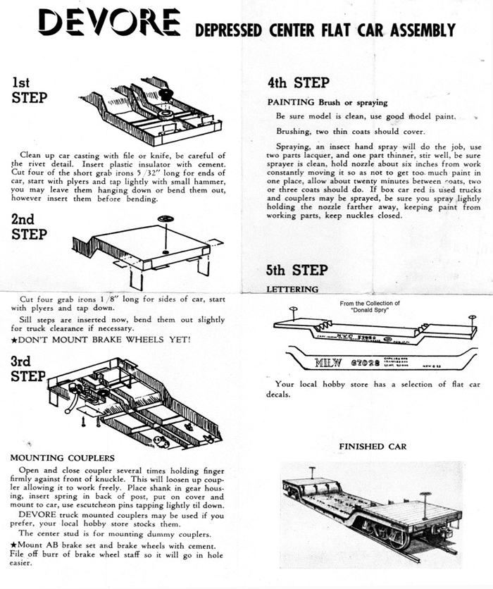
The kit in question is a Devore depressed-center flat car, a 40-foot car that was cast in white metal all in one piece. This kit dates back to the early 1950s, and when originally built, had oversize grabs and sill steps, along with Varney dummy couplers.
So what is this kit, really? I’m sure there are readers of this blog who have never seen a Devore kit box, so it’s shown below, in two images, both an angled view and the box end. You can click on the image if you wish to enlarge it.
You will notice in the image of the box end that this beauty cost all of $1.60 in that era.
Having a one-piece body, the kit instructions are simplicity itself. They did occupy a full sheet of paper, and are shown below. You can find old kit instructions like these on the HO Seeker web site (a great resource of its kind). You can click on this image to enlarge it if you wish.
I had damaged the sill steps in storage over the years, the Zamac truck sideframes had disintegrated, and the Varney dummy couplers just were not going to operate well with the Kadees on the rest of my fleet. And the paint was flaking off in places. I really don’t know what paint this might have been, but it was probably the Roundhouse 410-M product, of which I used a lot in that era.
So what’s needed here? I tried paint stripper to clean the paint off, but it hardly touched it, so I resorted to lacquer thinner, which did indeed soften it so it could be rubbed off. I was able to pull all the damaged grab irons from the body, and then used a #75 drill to make sure the mounting holes were all clear.
At that point, I began by installing the old grab irons to make the end grabs, that are inserted in holes in the bottom of the end sill, and then are bent 90 degrees to make them horizontal. These look somewhat okay, and aren’t very visible on a car in service, but they are quite oversize, as you will see in photos below.
Next I installed A-Line Style B sill steps at all four corners, and these did fit the mounting holes. The same was not true of the scale 18-inch grab irons I had on hand, so I had to bend new ones to fit the actual mounting hole spacing, about 21 inches. I used some bronze wire I had on hand, 0.013-inch diameter, then secured the grabs and steps with CA. In this photo, the side grab is barely discernible, but the sill step is clear.
A second photo shows the side grab more clearly, and you can compare it to the end grab’s oversize diameter.
What is needed next, to complete detailing, is to drill holes for the vertical-staff brake wheels at each end, which I clearly hadn’t done when I first assembled this kit (you can see the location in the photos above). That task, along with bringing the car weight up to the desired value, figuring how to install Kadee couplers, and choosing 70-ton trucks, will be covered in a future post.
Tony Thompson
Tuesday, October 29, 2019
The 2019 Chicagoland RPM meet
The 26th annual RPM event now called Chicagoland (long known as “Naperville” when we met in a hotel in that town) took place last week. As always, it functions as one of the “Freight Car Nationals” and was well attended by lots of the usual suspects. And also as always, the fellowship was an important part of the proceedings, something we all value.
Mike Skibbe did an excellent organizing job again, as he has done for I think four years now, and that really helps everything run smoothly. He knows the importance of the clinic program at an event like this, and it was up to the usual high standard. There is rarely a clinic time slot that doesn’t find me in a meeting room, and I enjoyed every one I viewed this year. For just a single example, below is Craig Wilson, about to begin his talk, “Loads on Open Cars,” which was quite interesting.
The hotel ballroom hosts two quite large modular layouts during the meeting, along with model displays (more on that in a moment) and a very active array of dealer tables. I can rarely get out of there without picking up a few irresistible items. Here’s an overview.
The model displays always fill a number of very large tables, and this year was no exception. I can only give the tiniest glimpse of what I saw, and will arbitrarily pick a couple of examples that I especially liked. Certainly one of those was this CPR reefer, a Trueline Trains model with metal ladders and lettering from Black Cat, modeled by John Riddell.
Another model I thought looked “just right” was this D&H box car by Hunter Hughson, one of the cars included in his fine clinic on car weathering.
Lastly, I really liked this load of boxcar doors, by Craig Wilson (shown above at his clinic), and in fact it’s one of the reasons I went to his clinic. We all have a few doors like this in our “parts box” (or scrap box, if you will), and Craig did confess that not all of these are actually doors; only the outermost parts of each stack need be an actual door, the rest can be pieces of styrene sheet . . .
One item of news I especially liked at this meet was the emergence of yet another Shippers Guide from Ted Schnepf of Rails Unlimited, this one for the Chicago & North Western. (For more on these publications, see my discussion at: https://modelingthesp.blogspot.com/2015/11/waybills-part-44-shipper-guides.html .) I of course bought one immediately.
I always enjoy this event — I have only missed a couple of the 26 that have been held so far — and look forward to many more. If you haven’t attended, and have any chance to attend this meet next year, I would urge you to give it a try. It’s a good one.
Tony Thompson
Subscribe to:
Posts (Atom)