This modeling project is one of the “Shake ’n’ Take” models from the Cocoa Beach meeting that’s called “Prototype Rails,” held every January in Cocoa Beach, Florida under the direction of Mike Brock. The idea came from Greg Martin, with assists from Jim Singer of 5th Avenue Car Shops, Richard Hendrickson, and Bob Walker and Dennis Storzek of Accurail. The Accurail refrigerator car kits which were the basis for this particular project, presented at the 2007 meeting, were decorated and donated by 5th Avenue Car Shops.
The prototype of the model refrigerator car is a former Fruit Growers Express (FGE) reefer, leased by E. Kahn’s Sons Co. of Cincinnati, Ohio, a meat packer, from National Car Company, a Fruit Growers subsidiary. To approximate one of these cars, the Accurail reefer kit was the starting point. That kit has a USRA fishbelly underframe, whereas the FGE car had a straight center sill (and several other differences in underframe construction). Correcting the stock kit underframe was one part of the project.
A second part was upgrading details, primarily removing cast-on grab irons and replacing with wire. This is normal detailing work and went easily. Lastly, end and roof details are modified. The entire directions for the project were provided in PDF form by Greg Martin, and with his permission are posted on Google Docs. Here is a link:
https://docs.google.com/open?id=0Bz_ctrHrDz4wNjlhNDU2NDEtMWQ2MC00ODJmLWFjNWQtMDFlMjY1YTE1ZWJi
I might mention that this handout states the paint scheme on this specific 5th Ave. Car Shops kit was introduced by Kahn’s in 1953. But there is a fine photo of a Kahn’s car with almost the exact same paint scheme, a car painted in November 1951, on page 197 of the book Billboard Refrigerator Cars (Richard H. Hendrickson and Edward S. Kaminski, Signature Press, 2008). So the scheme is earlier than stated by Greg, and poses no problem for my modeling year, 1953.
I decided to minimize the underframe modifications, since they are not very visible on a finished model. I did cut down the kit center sill to a straight configuration, and added a cover strip of 0.015 x 0.125-inch styrene. Changing the number of cross-bearers from five to four did not seem essential to me. Greg points out that the Accurail-provided locations of the brake gear are not exactly right for FGE cars, but they are in fact pretty close, so I chose to ignore that discrepancy also. Prior to adding brake rigging, here is my underframe appearance:
Let me emphasize that I am not suggesting my approach is “better” than the more complete and more accurate modeling outlined by Greg. I just applied my personal standards to this particular car and its intended use.
Carrying on to the body modifications, I used a chisel blade in my Exacto knife to remove molded-on side and end grab irons, and roof corner grabs. Using a scriber, I then made sure the grooves simulating wood siding boards were continuous through the places the molded grab irons had been. I then drilled holes to add wire grabs to all these locations. I cut away the poling pockets at car corners and filed the bottom of the car ends smooth, then added styrene channel (Evergreen 2 mm) at the bottom of the end to represent the end sill on these cars. With some grab irons added, at this point the body looked like this:
The end-sill grab irons were approximated with styrene rod. After these additions, the side grab irons were touched up with Floquil Reefer Yellow.
Upon completion of the underframe detailing and painting Grimy Black, I installed Kadee #58 couplers and the Accurail trucks with Reboxx wheelsets, which are my current standard couplers and wheels. Then turning over the underframe, I glued on two large steel nuts (5/8-inch size) using airplane canopy cement (I use an older Wilhold product, R/C-56, but its equivalents are readily available at any hobby shop selling plastic airplane models). Here’s the underframe at that point:
You can just see a bit of the brake rodding underneath the car.
On the car body, I added the “Modeler’s Choice” part 602 wood running board which was supplied in the “Shake ’n’ Take” kit, again using canopy cement. I added supports for the brake platform with styrene strip, scale 1 x 2-inch size, and 0.019-inch brass wire as the brake staff, and applied the kit brake wheel. Finally, short pieces of styrene strip, 0.020 x 0.060 inches, were added at the side sill corners (where poling pockets were removed), to represent the side sill extensions under the end sill channels. All these added parts were touched up with Floquil Boxcar Red, except the side sill, which I painted black.
Here is a photo of the A end of the car at this point, prior to weathering.
The extended side sill is just visible under the end-sill channel. There is a prototype photo of this same area, included in the directions linked above to Google Docs, which clearly shows the prototype end sill arrangement.
I added a reweigh date and a repacking stencil to my car prior to weathering, since I want to present the car as recently painted, rather than with the usual paint patches on older paint. I used both reweigh dates and repack data from the Speedwitch Fruit Growers decal set D119.1, which contains a variety of FGE (or National Car) reweigh locations like Plattesmouth (PLT), Hillyard (HILL), Alexandria (AX), Indiana Harbor (IH), and Jacksonville (JAX). If you’re not familiar with reweigh dates and all that they imply, you might like to read my article on the topic, in a corrected version from what appeared in Railroad Model Craftsman, available at: http://modelingthesp.blogspot.com/2011/03/reweigh-article-from-rmc.html .
My weathering method employs acrylic washes, as summarized in the joint clinic handout by Richard Hendrickson and me (if interested, it can be downloaded at: http://modelingthesp.blogspot.com/2011/10/weathering-clinic-handout.html ). Here is a photo of the lightly-weathered car, on the house track in my layout’s town of Ballard, being picked up as an empty after delivering a load of packing house products to my wholesale grocer, Peerless Foods.
That completes a pleasant and interesting model project. Thanks again to Greg Martin and his “Shake ’n’ Take” series at the Cocoa Beach meetings. As you can see, I have already put the car to work on the layout!
Tony Thompson
Friday, December 9, 2011
Thursday, December 8, 2011
One year and counting
Today is the anniversary of my beginning this blog. I started without any great confidence that I would have much to say for very long, and certainly without any sense that very many other people would be interested. In fact, if I’d made a prediction that day last year, I would have guessed that interest from readers would be rather slight, and that either that low response, or exhaustion of my own motivation, would have wound down the blog in a matter of months.
To my considerable surprise, there has been a lot of interest. As of today, there have been well over 51,000 page views of this blog since December 8, 2010 (excluding my own), and many posts have attracted multiple comments. And I have received a number of emails privately, from folks who I suppose didn’t think their question or comment needed to be public as a blog comment. And some of those private communications have stimulated further posts to expand upon or explore the subjects raised. These extensions have been an interesting experience for me, and hopefully informative for readers.
The total number of posts so far is 126, to me a surprising number, and though I thought these posts would be mostly brief, a few have been pretty long. I hadn’t realized I would use as many photos and other graphics as I have, and didn’t really expect to touch on so wide a range of topics. So this has been a more complex and gratifying experience than I imagined. I feel like I’m still learning how to use this medium effectively, which adds to the interest. Summing up, I have to say I’m more than pleased with it so far, and certainly still enjoying it.
If you’re a regular reader, thanks for your participation. Both for you and for those just occasionally visiting, I hope I can continue to provide material of interest.
Tony Thompson
To my considerable surprise, there has been a lot of interest. As of today, there have been well over 51,000 page views of this blog since December 8, 2010 (excluding my own), and many posts have attracted multiple comments. And I have received a number of emails privately, from folks who I suppose didn’t think their question or comment needed to be public as a blog comment. And some of those private communications have stimulated further posts to expand upon or explore the subjects raised. These extensions have been an interesting experience for me, and hopefully informative for readers.
The total number of posts so far is 126, to me a surprising number, and though I thought these posts would be mostly brief, a few have been pretty long. I hadn’t realized I would use as many photos and other graphics as I have, and didn’t really expect to touch on so wide a range of topics. So this has been a more complex and gratifying experience than I imagined. I feel like I’m still learning how to use this medium effectively, which adds to the interest. Summing up, I have to say I’m more than pleased with it so far, and certainly still enjoying it.
If you’re a regular reader, thanks for your participation. Both for you and for those just occasionally visiting, I hope I can continue to provide material of interest.
Tony Thompson
Monday, December 5, 2011
My column in MRH
The current issue of MRH (Model Railroad Hobbyist) magazine contains a column by me, for those who might be interested. The magazine is entirely electronic, no paper copies unless you print one out for yourself, and can be downloaded as a PDF (portable document format) to your computer. The magazine is free to anyone. To obtain a copy, go to http://model-railroad-hobbyist.com/magazine .
The column is part of a series called “Getting Real,” intended as views of prototype modeling opportunities and challenges from a variety of prototype-oriented modelers. To date these include Joe Fugate (editor of MRH), Mike Rose, Jack Burgess, Marty McGuirk, and me. Each of us is writing a column in rotation, so we submit one every five months.
My piece this month is entitled “Choosing a Model Freight Car Fleet” (abbreviated in the MRH Table of Contents as “Freight Car Fleet”), and essentially follows a couple of my blog posts on the subject, though not repeating any of them. Focus is on both the Gilbert-Nelson idea of foreign-car presence on any railroad, and on the appropriate percentage of home-road cars. The former topic was first discussed in this blog at the post entitled “Choosing a model car fleet-2,” available at: http://modelingthesp.blogspot.com/2010/12/choosing-model-car-fleet-2.html , and including the bar graph of railroad fleet sizes. The latter topic was discussed first in my post called “Modeling freight traffic: Coast Line, 1953-Part 7,” which can be seen at: http://modelingthesp.blogspot.com/2011/03/modeling-freight-traffic-coast-line_11.html , a post which described finding an SP home-road percentage in a conductor’s time book.
I did include in the column the bar graph of SP car types in 1950, a graph included in each of my volumes on SP freight cars. Beyond that, the column included an SP yard photo, just for flavor, a photo which was also included as a double-page spread in my Volume 5 on Southern Pacific Freight Cars (Signature Press, 2008), pages 104 and 105. Here is a smaller version to show the overall impression:
I feel that Joe Fugate is doing something worthwhile with this series on prototype-oriented modeling, and hope I can keep up with the distinguished company of my fellow columnists.
Tony Thompson
The column is part of a series called “Getting Real,” intended as views of prototype modeling opportunities and challenges from a variety of prototype-oriented modelers. To date these include Joe Fugate (editor of MRH), Mike Rose, Jack Burgess, Marty McGuirk, and me. Each of us is writing a column in rotation, so we submit one every five months.
My piece this month is entitled “Choosing a Model Freight Car Fleet” (abbreviated in the MRH Table of Contents as “Freight Car Fleet”), and essentially follows a couple of my blog posts on the subject, though not repeating any of them. Focus is on both the Gilbert-Nelson idea of foreign-car presence on any railroad, and on the appropriate percentage of home-road cars. The former topic was first discussed in this blog at the post entitled “Choosing a model car fleet-2,” available at: http://modelingthesp.blogspot.com/2010/12/choosing-model-car-fleet-2.html , and including the bar graph of railroad fleet sizes. The latter topic was discussed first in my post called “Modeling freight traffic: Coast Line, 1953-Part 7,” which can be seen at: http://modelingthesp.blogspot.com/2011/03/modeling-freight-traffic-coast-line_11.html , a post which described finding an SP home-road percentage in a conductor’s time book.
I did include in the column the bar graph of SP car types in 1950, a graph included in each of my volumes on SP freight cars. Beyond that, the column included an SP yard photo, just for flavor, a photo which was also included as a double-page spread in my Volume 5 on Southern Pacific Freight Cars (Signature Press, 2008), pages 104 and 105. Here is a smaller version to show the overall impression:
I feel that Joe Fugate is doing something worthwhile with this series on prototype-oriented modeling, and hope I can keep up with the distinguished company of my fellow columnists.
Tony Thompson
Thursday, December 1, 2011
Modeling the Glasshopper II
In the mid-1980s, when I lived in Pittsburgh, I participated in a project of the Pittsburgh Model Railroad Club (as it was then named), to build a small demonstration layout for the Lord Corporation of Erie, PA. Lord produced a number of railroad-related products, from rubberized grade crossings to a wide variety of coatings and linings for freight cars. They wanted a small HO scale layout which would feature their products, for publicity purposes.
The club set to work on this project, and produced a nice portable layout which I understand Lord did use, taking it to various conventions and so forth. One part of the project I worked on was to produce a model of the fiberglass covered hopper called the “Glasshopper.” Lord not only supplied an adhesive used in the car’s construction but also the polyurethane coating used on the outside. So what the heck was a Glasshopper?
The Glasshopper story had started back in 1973, when a severe car shortage caused James Springrose, then Vice President-Transportation for Cargill, to think about ways to increase payloads and thus need fewer cars. From then until 1978 Cargill worked on its own toward development of a lighter car body for covered hoppers, with fiberglass uppermost on the list of materials.
In 1978 a joint venture between Cargill, Southern Pacific, and ACF
Industries was created to build a prototype car, named the “Glasshopper,”
based on Cargill’s ideas. The novelty in construction was that long fiberglass filaments were wound onto a large mandrel to make a one-piece car body of otherwise conventional polyester-fiberglass material. This is in contrast to most of the familiar fiberglass products one sees, which use chopped (short) glass fibers in a polyester matrix. The goal of the Glasshopper project was a tare (light) weight of 52,000 pounds, well below that of other 100-ton covered hoppers.
The production process was dramatically different from other freight cars in that innocuous-sounding phrase, “one-piece car body.” The mandrel for the filament-winding process was the size of the complete car body. Here is an ACF photo of the process, which was carried out at ACF. Fiberglass pressure vessels can be fabricated this way too.
Once the basic body was completed, final assembly, including steel side sills and bolsters (the Center Flow design has no center sill), was accomplished at ACF. There was a detailed story about the first car in Railway Age for 30 March 1981 (pages 56 and 57), when it was put into service.
The club set to work on this project, and produced a nice portable layout which I understand Lord did use, taking it to various conventions and so forth. One part of the project I worked on was to produce a model of the fiberglass covered hopper called the “Glasshopper.” Lord not only supplied an adhesive used in the car’s construction but also the polyurethane coating used on the outside. So what the heck was a Glasshopper?
The Glasshopper story had started back in 1973, when a severe car shortage caused James Springrose, then Vice President-Transportation for Cargill, to think about ways to increase payloads and thus need fewer cars. From then until 1978 Cargill worked on its own toward development of a lighter car body for covered hoppers, with fiberglass uppermost on the list of materials.
In 1978 a joint venture between Cargill, Southern Pacific, and ACF
Industries was created to build a prototype car, named the “Glasshopper,”
based on Cargill’s ideas. The novelty in construction was that long fiberglass filaments were wound onto a large mandrel to make a one-piece car body of otherwise conventional polyester-fiberglass material. This is in contrast to most of the familiar fiberglass products one sees, which use chopped (short) glass fibers in a polyester matrix. The goal of the Glasshopper project was a tare (light) weight of 52,000 pounds, well below that of other 100-ton covered hoppers.
The production process was dramatically different from other freight cars in that innocuous-sounding phrase, “one-piece car body.” The mandrel for the filament-winding process was the size of the complete car body. Here is an ACF photo of the process, which was carried out at ACF. Fiberglass pressure vessels can be fabricated this way too.
Once the basic body was completed, final assembly, including steel side sills and bolsters (the Center Flow design has no center sill), was accomplished at ACF. There was a detailed story about the first car in Railway Age for 30 March 1981 (pages 56 and 57), when it was put into service.
The car was considered very successful, holding up well in service with a variety of loads, some of them corrosive. An additional unplanned test occurred in August 1982, when the car was involved in a derailment which included several other cars. As a spokesman for the joint venture put it, “the impact created by the derailment was such that it broke the Glasshopper’s coupler shank and caused the car to skid several hundred feet, leave the track, and slide down an embankment on its side. The car was righted, re-trucked, and returned to ACF’s Technical Center in St. Charles, Mo. for evaluation and minor repairs. These repairs primarily involved steel components such as ladders and outlets. The FRP (fiberglass-reinforced polyester) body was virtually unharmed.” (from Railway Age, January 1984, page 28)
Here is a photo of the car being retrieved from that derailment (photo courtesy Lord Corporation); note the upper left logo of Cargill, SP and ACF.
The Glasshopper was part of an imagined “new age” of freight car design, judging from the slightly breathless article by Railway Age senior editor Gus Welty, entitled “The new breed of freight cars: A material difference.” (Railway Age, May 25, 1981, pages 26-29)
The experience with the Glasshopper led to modified specifications for Glasshopper II. The original car was “somewhat conservative” in design, according to ACF, and still lighter weight was targeted. In addition, a cleaner interior design without bulkheads was considered feasible. The new car was announced as entering service in January 1984, although its “built date” was April 1983 (testing was conducted in the interim). Like the original Glasshopper, it superficially looked much like a conventional ACF Center Flow covered hopper, although its 15' 6" height put it into the “Plate C” extra-height category, and was again a one-piece filament-wound FRP body.Here is a three-quarter view of the Glasshopper II (courtesy Lord Corporation), with the same paint scheme of colored stripes as the original car, but numbered RNDX 166 instead of RNDX 163. Some of the bolt heads near the ends of the car sides reflect the assembly process. You can click on this image to enlarge it and see some of the end sheet configuration.
The Glasshopper experiments seem to have worked all right technically, and showed good durability and corrosion resistance. But they were more expensive to construct and harder to repair than conventional cars, with only about a 6 percent advantage in total weight. As far as I know, they were not duplicated. You can read more in a couple of places: D.C. Ruhmann’s paper in the journal Composite Structures, Vol. 27, 1994, pages 207-213; and in the book Reinforced Plastics Handbook, 3rd edition, D.V. Rosato, D.V. Rosato, and J. Murphy, Elsevier, 2004, pages 530-535.
Modeling either of the Glasshoppers presents some challenges if the car is to be duplicated accurately. The car body had numerous, though minor, differences from the conventional ACF body, and the stripes and lettering of the paint scheme are not available in any commercial decal or dry transfer. I decided to minimize the modeling problems and essentially convert the Athearn ACF car to an approximate representation of an HO Glasshopper II. Once this decision is made, most effort focuses on the car ends, since they are the most distinctive major difference. The Giasshopper II was also a 3-bay hopper, unlike the original Glasshopper and the Athearn model, which are 4-bay cars.
As a starting point, I chose the Athearn “Co-op Fertilizer” car, kit No. 1909, because it is white. Ordinarily I prefer to work on an undecorated body, but since the final base color of the Glasshopper is white, some of the paint coverage difficulties of white paint over black plastic can be avoided by using Athearn’s paint as a base coat Unfortunately, little of the Athearn lettering can be salvaged. I used only the “Caution” notice at the center of the side sill and the dimensional data (these were later covered with tape when overspraying the completed model with white).
The underframe modification is simple. The end hoppers on the Athearn car are in very nearly the correct location, so the modification is to replace the two center hoppers with a single one. The Athearn model has flat (horizontal) “floor” segments between each hopper. I sawed through the center of each of these, then used styrene cement to attach the two frame ends and one of the hoppers to a piece of 0.040 styrene sheet, about 30 scale feet long, for stiffness. The Athearn weight attaches to pins on the underframe, and can be used as a spacer to maintain the correct final length of the modified frame. The outlet gates on the Glasshopper were horizontal sliders, more like the ones on the Athearn Pullman-Standard (ribbed side) car than the ACF model, but I chose to ignore this detail. If you choose the model the original Glasshopper, you need make no underframe changes (again, except outlet gates).
The ends, as mentioned, are distinctive, and were essentially the same on both Glasshoppers. Here is how I modified the Athearn slope sheet/end part to resemble the Glasshopper end. The Glasshopper had a smooth slope sheet except for a horizontal angle, and the end below the slope sheet had deep, formed ribs running vertically. The large diagonal stiffeners on the Athearn end accordingly were removed. There is also a small horizontal rib on the Athearn slope sheet; this was retained, and a piece of 0.020-inch styrene, 6 scale inches wide and as long as the end width, was glued on edge along that rib to represent the Glasshopper’s horizontal angle.
The photo below shows the stock Athearn end (lettered for Athearn’s version of the Glasshopper I, discussed below). You can see the large diagonal stiffeners which had to be removed.
The Athearn lower end sheet, the vertical part, was turned into the five ribs of the Glasshopper by dividing the end horizontally into eleven parts, marking parallel vertical lines, and razor-sawing along each of the lines up to the slope sheet. Then every other sawed strip was removed, starting at either edge, so that five ribs remained. The center one lies across the hole in the original end sheet, and to make it full length, one of the removed strips was fitted. Now a piece of 0.020-inch styrene was glued behind the ribs, so that when the slope sheet/end piece is in place, the face of the ribs will be flush with the edge of the cut-out in the car side, as on the prototype. At this point, I installed (but didn’t glue) the slope sheet/end part into the body. The Glasshopper end also has lighter diagonal angles flush with the plane of the end ladders. I modeled these with 1/16-inch Plastruct angles, cut to fit, and added small gussets from 0.010-inch styrene sheet.
Here is an angled end view of the completed model, to illustrate the work on the ends, though it would have been better to photograph the modified end piece before inserting it into the car body.
The car side can be made to resemble the Glasshopper II by removing the narrow rib of the Athearn car side, about two-thirds of the way up the side, and by filing the “overhang” at the top of the car side so it is vertical rather than overhanging. If you wish to model the original Glasshopper, the sides curved smoothly onto the top, with about a 2-foot (scale) radius; the Athearn body has enough material to permit filing to this contour.
Lastly, the “trough” hatches were added. These hatches do not duplicate the fiberglass hatches on the Glasshopper, which had ribs running across the hatch rather than the lengthwise ribs on the Athearn hatches, but the general appearance was acceptable to me.
The model car resulting from this work is only an approximation to the Glasshopper, not only because there are several detail differences remaining, but also because the Athearn car is not as tall as the Glasshopper. To remedy the height would be a larger project than I was interested in.
Turning now to finishing, I assembled the underframe to the body, carefully locating the slope sheet/ends with the underframe tabs, and used modeler’s putty to fill the gap where the top of the slope sheet meets the body. This would also be the time to fill any other gaps or gouges from construction work. I also added a Walthers white metal Ajax brake wheel. Several light coats of Floquil Reefer White were sprayed on until the color was uniform. This was given several days to dry thoroughly before starting work on the stripes.
Using the prototype photos as a guide, drafting tape (not masking tape) was cut into strips 3 scale inches wide to define the gaps between the stripes. These were then applied with 9 inch separations for the stripe width. These were pressed down firmly, along with tape to cover the rest of the body. Additional pieces of tape were prepared with low stickiness or “tack” by applying and removing them several times to the sheet of glass I use for cutting. These covered the stripes not being painted at any one time.
The stripe colors require some mixing. Choosing the exact color is difficult because the photos of the prototype Glasshoppers differ considerably in color rendition with the lighting conditions. Accordingly, I felt that an exact match was neither necessary nor very practical. The upper stripe was mixed from Boxcar Red with a few drops of Roof Brown; the second stripe was painted with straight Pullman Green; the third stripe was mixed from Reefer Orange with several drops of Black; and the bottom stripe was mixed from Foundation with several drops each of Roof Brown and Black.
I painted all of these Floquil colors with light spray coats, in one painting session, by allowing about 15 minutes between colors for drying (while I was mixing the next color) and occasional using of a hair dryer to speed the process. I had no trouble with covering the prior stripes with the low-tack tape, but if it sounds risky to you, you could spread the process over two or more sessions.
The “Plate C” label and the small lettering on sides and ends was taken from a Walthers modern covered hopper decal set, No. D561. Some of the capacity data was pieced together, since I decided to reproduce all the correct numbers in that group. These are:
CAPY 200 000 LO
LD LMT 208 800
LT WT 54 200 NEW 4-83
On the side sill under this lettering is the legend, “1 1/2 IN HF COMP SHOE” (this can be pieced from the Walthers set; it refers to the 1.5-inch-high friction composition brake shoes). This also appears at the other end of the car, beyond the “lube plates.” My lube plates were taken from a Herald King set remnant I had on hand; they are available from several decal makers.
The remaining lettering comprises the reporting marks and number, the Cargill-SP-ACF logo, and the large Glasshopper II name. Since no commercial products are close to these items, all were made as dry transfers. Artwork was made for these by tracing from an enlargement of a prototype photograph, then having the transfers made commercially by the 3M “Image-N-Transfer” process (this process was later sold to Letraset; I understand there are still graphic arts suppliers who do custom transfers this way). I have the lettering artwork available and would be happy to make it available to anyone who wants to make decals or dry transfers.
After applying these transfers, the car was oversprayed with Testor’s Dullcote. The prototype is actually rather glossy, as a polyurethane coating was applied to the exterior, but HO scale models with high gloss simply do not look realistic. I finished the car with a bit of Grimy Black on trucks, since the car is modeled in its nearly-new condition. Here is how it looked (the photo is a little washed out):
Unfortunately, I no longer have this model. It was part of the Lord layout project, and went with the layout on its travels. I’ve never learned what was the final disposition of that display layout, or of its structures and rolling stock.
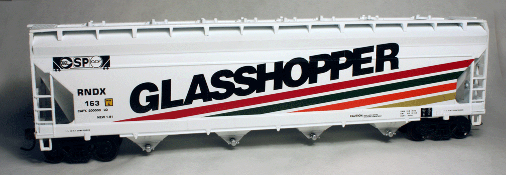
Athearn has done a commercial lettering version of the original Glasshopper by simply putting the lettering on their standard ACF Center-Flow car. The ends are unmodified, but the appearance in a side view is good, and the car does have the correct four bays of the first Glasshopper. Here is a side view:
The stripe colors here seem deeper than what I modeled, and deeper than the prototype photos I have, but do represent the general appearance well.
Although this prototype is well beyond my own modeling era, it was an interesting challenge to research and build, and after all, this car does have a Southern Pacific connection!
Here is an angled end view of the completed model, to illustrate the work on the ends, though it would have been better to photograph the modified end piece before inserting it into the car body.
The car side can be made to resemble the Glasshopper II by removing the narrow rib of the Athearn car side, about two-thirds of the way up the side, and by filing the “overhang” at the top of the car side so it is vertical rather than overhanging. If you wish to model the original Glasshopper, the sides curved smoothly onto the top, with about a 2-foot (scale) radius; the Athearn body has enough material to permit filing to this contour.
Lastly, the “trough” hatches were added. These hatches do not duplicate the fiberglass hatches on the Glasshopper, which had ribs running across the hatch rather than the lengthwise ribs on the Athearn hatches, but the general appearance was acceptable to me.
The model car resulting from this work is only an approximation to the Glasshopper, not only because there are several detail differences remaining, but also because the Athearn car is not as tall as the Glasshopper. To remedy the height would be a larger project than I was interested in.
Turning now to finishing, I assembled the underframe to the body, carefully locating the slope sheet/ends with the underframe tabs, and used modeler’s putty to fill the gap where the top of the slope sheet meets the body. This would also be the time to fill any other gaps or gouges from construction work. I also added a Walthers white metal Ajax brake wheel. Several light coats of Floquil Reefer White were sprayed on until the color was uniform. This was given several days to dry thoroughly before starting work on the stripes.
Using the prototype photos as a guide, drafting tape (not masking tape) was cut into strips 3 scale inches wide to define the gaps between the stripes. These were then applied with 9 inch separations for the stripe width. These were pressed down firmly, along with tape to cover the rest of the body. Additional pieces of tape were prepared with low stickiness or “tack” by applying and removing them several times to the sheet of glass I use for cutting. These covered the stripes not being painted at any one time.
The stripe colors require some mixing. Choosing the exact color is difficult because the photos of the prototype Glasshoppers differ considerably in color rendition with the lighting conditions. Accordingly, I felt that an exact match was neither necessary nor very practical. The upper stripe was mixed from Boxcar Red with a few drops of Roof Brown; the second stripe was painted with straight Pullman Green; the third stripe was mixed from Reefer Orange with several drops of Black; and the bottom stripe was mixed from Foundation with several drops each of Roof Brown and Black.
I painted all of these Floquil colors with light spray coats, in one painting session, by allowing about 15 minutes between colors for drying (while I was mixing the next color) and occasional using of a hair dryer to speed the process. I had no trouble with covering the prior stripes with the low-tack tape, but if it sounds risky to you, you could spread the process over two or more sessions.
The “Plate C” label and the small lettering on sides and ends was taken from a Walthers modern covered hopper decal set, No. D561. Some of the capacity data was pieced together, since I decided to reproduce all the correct numbers in that group. These are:
CAPY 200 000 LO
LD LMT 208 800
LT WT 54 200 NEW 4-83
On the side sill under this lettering is the legend, “1 1/2 IN HF COMP SHOE” (this can be pieced from the Walthers set; it refers to the 1.5-inch-high friction composition brake shoes). This also appears at the other end of the car, beyond the “lube plates.” My lube plates were taken from a Herald King set remnant I had on hand; they are available from several decal makers.
The remaining lettering comprises the reporting marks and number, the Cargill-SP-ACF logo, and the large Glasshopper II name. Since no commercial products are close to these items, all were made as dry transfers. Artwork was made for these by tracing from an enlargement of a prototype photograph, then having the transfers made commercially by the 3M “Image-N-Transfer” process (this process was later sold to Letraset; I understand there are still graphic arts suppliers who do custom transfers this way). I have the lettering artwork available and would be happy to make it available to anyone who wants to make decals or dry transfers.
After applying these transfers, the car was oversprayed with Testor’s Dullcote. The prototype is actually rather glossy, as a polyurethane coating was applied to the exterior, but HO scale models with high gloss simply do not look realistic. I finished the car with a bit of Grimy Black on trucks, since the car is modeled in its nearly-new condition. Here is how it looked (the photo is a little washed out):
Unfortunately, I no longer have this model. It was part of the Lord layout project, and went with the layout on its travels. I’ve never learned what was the final disposition of that display layout, or of its structures and rolling stock.
Athearn has done a commercial lettering version of the original Glasshopper by simply putting the lettering on their standard ACF Center-Flow car. The ends are unmodified, but the appearance in a side view is good, and the car does have the correct four bays of the first Glasshopper. Here is a side view:
The stripe colors here seem deeper than what I modeled, and deeper than the prototype photos I have, but do represent the general appearance well.
Although this prototype is well beyond my own modeling era, it was an interesting challenge to research and build, and after all, this car does have a Southern Pacific connection!
Tony Thompson
Sunday, November 27, 2011
Freight fleet rosters
I’ve discussed in several prior posts the approach I have taken and continue to take to developing a freight car roster. In particular, there are two parts to the problem: the mix of foreign cars, and the proportion of home-road cars. I follow the Gilbert-Nelson idea for my fleet of foreign cars (see my post at: http://modelingthesp.blogspot.com/2010/12/choosing-model-car-fleet-2.html) and have settled on about one-third of all freight cars to be home-road cars, based on conductor’s time books for the Coast Line (using data presented, analyzed and described previously at: http://modelingthesp.blogspot.com/2011/03/modeling-freight-traffic-coast-line_11.html ).
But beyond the railroads which are chosen, what cars and car types should that fleet of foreign cars contain? In this post, I discuss my approach to analyzing my various groups of foreign cars.
Gilbert-Nelson tells me what proportions of foreign cars to have, but does not tell me which cars. My choices, then, are based on several factors. First, numerically important car groups of various foreign railroads. Just as Gilbert-Nelson suggests that the total number of cars of a foreign road should be in proportion to their proportion in the total national car fleet, it seems reasonable to assume that the more numerous groups of cars would similarly be most visible. Second, available models: in most cases, I am not sufficiently fascinated by foreign roads to want to scratchbuild freight cars for them, though kitbashing is within the bounds of feasible work, to me.
A third factor is car types. Gilbert-Nelson, as often observed, ought only to work for free-running car types, meaning box cars, gondolas and flat cars, provided of course that the cars have no special equipment. Other car types have to be selected based on what is known from photographs and time books, along with expected industrial needs on my particular layout, leavened with some sense of what is a rarity and what is merely unusual.
For example, I have a photo of San Luis Obispo yard in the 1950s which includes a MKT stock car; similarly, there is a Morris Abowitz photo at Los Angeles in the late 1950s of an empty Reading hopper car. I conclude that both are genuine rarities, and I have decided to model neither car.
On the other hand, despite the absence of specific photographic evidence, I know from interviews and other documents that domestic coal (widely used on the SP in the 1950s for everything from section houses and cabooses, to depots, foremen’s houses, and sandhouse sand driers) came largely from eastern Utah and western Colorado. The mines were served by D&RGW, UP, and Utah Coal Route (UCR), and most of this traffic at this time was carried in drop-bottom (GS) gondolas. I am developing a number of such cars to handle my layout coal shipments.
(I made this point about coal traffic and GS gondolas in my post about my freight car fleet of gondolas; see the post at: http://modelingthesp.blogspot.com/2011/04/choosing-model-car-fleet-8-gondolas.html. That post also contains a photo of a UCR gondola.)
My basic roster analysis is to break down my fleet by railroad, and look at what I have (and plan to have) for each individual road to see if it makes sense. I will use D&RGW as an example. Though a Western road, it had a tight relationship with Western Pacific and Missouri Pacific for long-distance traffic, and thus minimal interchange with SP. But of course its cars still carried traffic into SP territory, and California photos do confirm the presence of D&RGW box and stock cars, as well as coal cars, in the early 1950s.
My roster, existing and planned, for D&RGW looks like this. I have a Westerfield single-sheathed box car, representing the 1916-built cars which were a mainstay of the Rio Grande fleet, and a Sunshine kit for the 1941 steel box cars, which may be enough for that car type. My stock car is an illustration of the pitfalls of trying to achieve accurate models. Combining reading about Rio Grande stock cars, and looking at a variety of photos, I concluded that I could model one of the cars D&RGW modernized with steel ends and roofs.
Here’s what I did. The sides of the modernized Rio Grande cars look a lot like the Athearn stock car, but as is well known, the Athearn stock car’s diagonal-panel roof has a reversed panel arrangement, and in any case is too new for the D&RGW cars, as are the Improved Dreadnaught ends of the Athearn model. I simply cut the sides from an Athearn stock car and from an Athearn box car, and put the stock car sides into the box car ends and roof. Why is this wrong? What I didn’t realize from the photographs I had examined is that the Rio Grande cars had corrugated ends, not Dreadnaught ones like the Athearn car. Sigh. Here’s a photo of my model:
I had to carve off the Athearn molded-on lettering boards, and decided to model a single broken board just left of the door. (Though I’m not sure a car inspector would have passed such a car.) The car continues in service on my layout, but is definitely a stand-in.
I have three cars for Utah coal, a pair of MDC triple hoppers (not quite correct but adequate stand-ins) and a 47-foot GS gondola, a brass W&R model. The old Ulrich D&RGW GS gondola I used to employ as a stand-in is only 40 feet long and thus not at all correct for the D&RGW cars, and is in my “sale” pile.
This is a comparison of the 40-foot and 47-foot cars. The proportions are quite different.
I’ve added an InterMountain early covered hopper and a Proto2000 53-foot flat car to round out my D&RGW fleet. So to me it looks like finishing that Sunshine boxcar kit will complete an adequate Rio Grande car fleet. I don’t have anything really surplus (except that Ulrich car) and don’t need any additions.
This kind of analysis is slowly being extended to other railroads, in each case looking to see whether I have too few or too many cars. The ultimate goal is a fleet of foreign freight cars which is at the same time representative of each foreign railroad, of an appropriate size, and of appropriate car types.
Tony Thompson
But beyond the railroads which are chosen, what cars and car types should that fleet of foreign cars contain? In this post, I discuss my approach to analyzing my various groups of foreign cars.
Gilbert-Nelson tells me what proportions of foreign cars to have, but does not tell me which cars. My choices, then, are based on several factors. First, numerically important car groups of various foreign railroads. Just as Gilbert-Nelson suggests that the total number of cars of a foreign road should be in proportion to their proportion in the total national car fleet, it seems reasonable to assume that the more numerous groups of cars would similarly be most visible. Second, available models: in most cases, I am not sufficiently fascinated by foreign roads to want to scratchbuild freight cars for them, though kitbashing is within the bounds of feasible work, to me.
A third factor is car types. Gilbert-Nelson, as often observed, ought only to work for free-running car types, meaning box cars, gondolas and flat cars, provided of course that the cars have no special equipment. Other car types have to be selected based on what is known from photographs and time books, along with expected industrial needs on my particular layout, leavened with some sense of what is a rarity and what is merely unusual.
For example, I have a photo of San Luis Obispo yard in the 1950s which includes a MKT stock car; similarly, there is a Morris Abowitz photo at Los Angeles in the late 1950s of an empty Reading hopper car. I conclude that both are genuine rarities, and I have decided to model neither car.
On the other hand, despite the absence of specific photographic evidence, I know from interviews and other documents that domestic coal (widely used on the SP in the 1950s for everything from section houses and cabooses, to depots, foremen’s houses, and sandhouse sand driers) came largely from eastern Utah and western Colorado. The mines were served by D&RGW, UP, and Utah Coal Route (UCR), and most of this traffic at this time was carried in drop-bottom (GS) gondolas. I am developing a number of such cars to handle my layout coal shipments.
(I made this point about coal traffic and GS gondolas in my post about my freight car fleet of gondolas; see the post at: http://modelingthesp.blogspot.com/2011/04/choosing-model-car-fleet-8-gondolas.html. That post also contains a photo of a UCR gondola.)
My basic roster analysis is to break down my fleet by railroad, and look at what I have (and plan to have) for each individual road to see if it makes sense. I will use D&RGW as an example. Though a Western road, it had a tight relationship with Western Pacific and Missouri Pacific for long-distance traffic, and thus minimal interchange with SP. But of course its cars still carried traffic into SP territory, and California photos do confirm the presence of D&RGW box and stock cars, as well as coal cars, in the early 1950s.
My roster, existing and planned, for D&RGW looks like this. I have a Westerfield single-sheathed box car, representing the 1916-built cars which were a mainstay of the Rio Grande fleet, and a Sunshine kit for the 1941 steel box cars, which may be enough for that car type. My stock car is an illustration of the pitfalls of trying to achieve accurate models. Combining reading about Rio Grande stock cars, and looking at a variety of photos, I concluded that I could model one of the cars D&RGW modernized with steel ends and roofs.
Here’s what I did. The sides of the modernized Rio Grande cars look a lot like the Athearn stock car, but as is well known, the Athearn stock car’s diagonal-panel roof has a reversed panel arrangement, and in any case is too new for the D&RGW cars, as are the Improved Dreadnaught ends of the Athearn model. I simply cut the sides from an Athearn stock car and from an Athearn box car, and put the stock car sides into the box car ends and roof. Why is this wrong? What I didn’t realize from the photographs I had examined is that the Rio Grande cars had corrugated ends, not Dreadnaught ones like the Athearn car. Sigh. Here’s a photo of my model:
I had to carve off the Athearn molded-on lettering boards, and decided to model a single broken board just left of the door. (Though I’m not sure a car inspector would have passed such a car.) The car continues in service on my layout, but is definitely a stand-in.
I have three cars for Utah coal, a pair of MDC triple hoppers (not quite correct but adequate stand-ins) and a 47-foot GS gondola, a brass W&R model. The old Ulrich D&RGW GS gondola I used to employ as a stand-in is only 40 feet long and thus not at all correct for the D&RGW cars, and is in my “sale” pile.
This is a comparison of the 40-foot and 47-foot cars. The proportions are quite different.
I’ve added an InterMountain early covered hopper and a Proto2000 53-foot flat car to round out my D&RGW fleet. So to me it looks like finishing that Sunshine boxcar kit will complete an adequate Rio Grande car fleet. I don’t have anything really surplus (except that Ulrich car) and don’t need any additions.
This kind of analysis is slowly being extended to other railroads, in each case looking to see whether I have too few or too many cars. The ultimate goal is a fleet of foreign freight cars which is at the same time representative of each foreign railroad, of an appropriate size, and of appropriate car types.
Tony Thompson
Tuesday, November 22, 2011
Waybills, Part 15: Managing bills
I have alluded in prior posts to the ways I manage waybills on my layout, but have not been very specific about it. This post addresses the matter directly.
As I mentioned in describing the role of the local agent in my operating scheme, including waybill management (see the post at: http://modelingthesp.blogspot.com/2011/10/operations-role-of-agent.html ), the use of a “bill box” at a station location can substitute for a person acting as agent, for example in a location with limited aisle space. I’ll repeat the photo I showed then, with a bill box in place on the shelf below my town of Shumala:
This not only emphasizes a prototype arrangement, but also removes aisle-side racks or other “display” arrangements which are less prototypical.
This bill box is a standard office item, a storage box for “index cards” or 3 x 5-inch cards, 3 inches deep. Years ago, oak boxes like this were available at any stationery store, but today one needs to seek them out on line, for example at Hedberg’s site, http://www.successimage.com/cat--Card-Files--CardFiles (and there are other sources, readily discovered). If need be, one can obtain hardwood index-card boxes deeper than 3 inches, and one can also buy sizes suitable for “mini-bills” or modern waybills 4 inches high, such as 4 x 6-inch card boxes, again of varying depths. Each layout may need a different set of such boxes to serve as bill boxes at different locations.
You can of course use the molded plastic versions of these boxes, much cheaper and more readily purchased locally, though I find them clunkier than I want. And in the greater scheme of layout expenses, the cost difference is not significant.
Within each card box, I have index tabs for the industries in town, for my own convenience in managing waybills, but the “business” part of the box is the front, where I put a packet of waybills for the next-arriving local freight crew, and any accompanying message needed to direct their work. Here is the Ballard box interior (index tabs are temporary hand-written versions), including a supply of blank Bad Order Bills:
Note that there is enough “head room” in the box that my waybills and sleeves can stand upright.
My off-layout cars and car sleeves are on shelves (some cars are packed in boxes, but the most active cars are shelved). When one of these cars is needed to go into action, its sleeve is right with it. I plan to show my shelving system in a future post.
But there are additional sleeves for the non-shelved cars, and lots of waybills not currently in use. These I keep in a file box designed for baseball cards. These are available from several suppliers; I use BCW (visit http://www.bcwsupplies.com/products/corrugated-storage-boxes/ for more info; there are four pages of box listings). They call it a “Shoe Storage Box,” and it is indeed reminiscent of a shoe box. Note that it has a lid.
You can see that at present, I’m using less than half of the space in this box, and I find the remainder is useful for supplies. They do offer both smaller and larger versions of this shoe-box style. Here’s a closer look at the index tabs (I use the “Trading Card Dividers” from BCW). These are “writable” plastic dividers, but I have labeled them with the same clear Avery labels that I use for waybill sleeves. Stored car sleeves are in the front of the box, filed by car type; waybills toward the back, filed by industry.
I also use a smaller box from BCW to store sleeves and waybills for my staging tracks. This box is what BCW calls a “200 Count Storage Box,” and it is available in several sizes (it comes with a lid, but I cut the lid off for convenient access.) Here again I use index tabs for each track number. These numbered index tabs are standard stationery-store items, cut down to fit the box. In this box, the car sleeves lie on their sides behind each tab.
I often keep a few Bad Order Bills and Empty Car Bills in the front of this box, but have removed them for this photo.
Here is a side view of the box itself (that’s the Ballard depot behind it):
In this view, some of the empty bills, and a train pack, are in the front of this box. This is usually the pack for the next local due out.
The train pack envelope is just made from a standard envelope, 3.5 x 6.5 inches, in manila, by cutting into two parts just off-center, leaving an offset, so each envelope half has a “back riser,” as you see here. Then the flap is glued closed.
These drop into a shirt pocket and are a convenient way for a train crew to carry their waybills.
This system evolved from a similar set of arrangements for the old Doug Smith/Allen McClelland car cars (3 x 5 inches), in use for several years on my old layout, and has simply been adopted to suit the smaller baseball-card size waybills. It’s been working well on my layout.
Tony Thompson
As I mentioned in describing the role of the local agent in my operating scheme, including waybill management (see the post at: http://modelingthesp.blogspot.com/2011/10/operations-role-of-agent.html ), the use of a “bill box” at a station location can substitute for a person acting as agent, for example in a location with limited aisle space. I’ll repeat the photo I showed then, with a bill box in place on the shelf below my town of Shumala:
This not only emphasizes a prototype arrangement, but also removes aisle-side racks or other “display” arrangements which are less prototypical.
This bill box is a standard office item, a storage box for “index cards” or 3 x 5-inch cards, 3 inches deep. Years ago, oak boxes like this were available at any stationery store, but today one needs to seek them out on line, for example at Hedberg’s site, http://www.successimage.com/cat--Card-Files--CardFiles (and there are other sources, readily discovered). If need be, one can obtain hardwood index-card boxes deeper than 3 inches, and one can also buy sizes suitable for “mini-bills” or modern waybills 4 inches high, such as 4 x 6-inch card boxes, again of varying depths. Each layout may need a different set of such boxes to serve as bill boxes at different locations.
You can of course use the molded plastic versions of these boxes, much cheaper and more readily purchased locally, though I find them clunkier than I want. And in the greater scheme of layout expenses, the cost difference is not significant.
Within each card box, I have index tabs for the industries in town, for my own convenience in managing waybills, but the “business” part of the box is the front, where I put a packet of waybills for the next-arriving local freight crew, and any accompanying message needed to direct their work. Here is the Ballard box interior (index tabs are temporary hand-written versions), including a supply of blank Bad Order Bills:
Note that there is enough “head room” in the box that my waybills and sleeves can stand upright.
My off-layout cars and car sleeves are on shelves (some cars are packed in boxes, but the most active cars are shelved). When one of these cars is needed to go into action, its sleeve is right with it. I plan to show my shelving system in a future post.
But there are additional sleeves for the non-shelved cars, and lots of waybills not currently in use. These I keep in a file box designed for baseball cards. These are available from several suppliers; I use BCW (visit http://www.bcwsupplies.com/products/corrugated-storage-boxes/ for more info; there are four pages of box listings). They call it a “Shoe Storage Box,” and it is indeed reminiscent of a shoe box. Note that it has a lid.
You can see that at present, I’m using less than half of the space in this box, and I find the remainder is useful for supplies. They do offer both smaller and larger versions of this shoe-box style. Here’s a closer look at the index tabs (I use the “Trading Card Dividers” from BCW). These are “writable” plastic dividers, but I have labeled them with the same clear Avery labels that I use for waybill sleeves. Stored car sleeves are in the front of the box, filed by car type; waybills toward the back, filed by industry.
I also use a smaller box from BCW to store sleeves and waybills for my staging tracks. This box is what BCW calls a “200 Count Storage Box,” and it is available in several sizes (it comes with a lid, but I cut the lid off for convenient access.) Here again I use index tabs for each track number. These numbered index tabs are standard stationery-store items, cut down to fit the box. In this box, the car sleeves lie on their sides behind each tab.
I often keep a few Bad Order Bills and Empty Car Bills in the front of this box, but have removed them for this photo.
Here is a side view of the box itself (that’s the Ballard depot behind it):
In this view, some of the empty bills, and a train pack, are in the front of this box. This is usually the pack for the next local due out.
The train pack envelope is just made from a standard envelope, 3.5 x 6.5 inches, in manila, by cutting into two parts just off-center, leaving an offset, so each envelope half has a “back riser,” as you see here. Then the flap is glued closed.
These drop into a shirt pocket and are a convenient way for a train crew to carry their waybills.
This system evolved from a similar set of arrangements for the old Doug Smith/Allen McClelland car cars (3 x 5 inches), in use for several years on my old layout, and has simply been adopted to suit the smaller baseball-card size waybills. It’s been working well on my layout.
Tony Thompson
Saturday, November 19, 2011
Route cards — 4
An important detail of the locations of route card boards for my modeling is for PFE steel refrigerator cars. (This follows my previous post on route card boards, linked here: http://modelingthesp.blogspot.com/2011/11/route-cards-3.html .) I have quite a few PFE cars on my layout, and they need to have correct locations for route cards and the occasional placard. When I looked into this topic, it turned out to be a little complicated.
It turns out that PFE changed location of placard boards, though not of route card boards, on almost every class of steel cars in the transition era, that is, up to 1955. (I model 1953.) I will illustrate this point with photos of the various classes (much more information and additional photos are in the book, Pacific Fruit Express (2nd edition), Anthony W. Thompson, Robert J. Church, and Bruce H. Jones, Signature Press, 2000. The photos I am showing here were chosen to show the route card board locations, not as outstanding portraits of the various classes. The book generally has much better images to illustrate the classes.
The first PFE steel ice cars were built in 1936 and 1937, Class R-40-10. As was common for reefers of many owners at the time, these cars had no placard board. Their route card board was on the side sill tab at the left bolster (PFE photo, author’s collection):
As pointed out in the previous post on route cards, many car types had this left-bolster location for route card boards.
The following class, R-40-14, was built in 1941. These cars continued to have their route card boards at the left bolster, as is just visible here (click on the image to enlarge it), but a placard board, painted black, was applied to the right of the car door (R.H. McFarland photo, Arnold Menke collection):
The next class, R-40-20, was built in 1945. Now a smaller board was added to the left of the door, with the placard board still on the right. The route card board was again installed at the left bolster (General American photo, author’s collection):
Only two years later, in 1947, PFE’s largest class of steel cars was built, Class R-40-23, and now the placard board was moved to the left of the car door and a little higher, and the smaller board seen on Class R-40-20 was omitted. And once again, the route card board was applied at the left bolster (Wilbur C. Whittaker photo, author’s collection):
A route card is visible on this car’s board.
Two more years elapsed before the construction of Class R-40-25 in 1949. Now the placard board remained as in Class R-40-23, but was joined by a smaller board below it. Both boards were now painted orange. The bolster location of a route card board was retained, as can be seen in this view at Los Angeles Shop (PFE photo, author’s collection):
The last class of any size in my pre-1955 discussion was Class R-40-26, built in 1952 and the first class built new with sliding doors. This class had board locations duplicating those of Class R-40-25, including the route card board; all boards were now orange (PFE photo, author’s collection):
It’s worth mentioning, by the way, that all these views are of as-built cars. When a car was shopped in the years after its construction, it normally would have its placard and other boards applied or moved in accord with current practice at that time. Thus older cars in a year like 1953 would mostly have updated board locations. In particular, older cars with paint schemes from later years should definitely have placard board patterns matching the era of the paint scheme.
What about models in HO scale? Without putting too fine a point on it, the simple fact is that few models of steel PFE cars have had a route card board at the bolster (only one I know of is the InterMountain or IM R-40-10 model), and many have lacked or had incorrect placard boards as well.
Here is a photo of an IM model of the R-40-10, having black-white heralds and thus also having the post-1949 placard boards (painted orange); the IM versions of R-40-10 representing as-built cars correctly have no placard boards. I have added a route card to the model’s board, located on the side sill at the bolster.
If needed, placard boards are easily added with thin styrene sheet. The prototype placard board was 16 inches high and 24 inches long, often tongue-and-groove construction so without a visible separation of the boards, or in later years sometimes plywood. I have occasionally scribed the board separations but in most prototype photos they are not visible. The smaller boards on reefer car sides varied, but were often about 8 inches square. The same appears true of the route card boards on steel box car doors.
This model shown below is an old Athearn plastic reefer, representing Class R-40-23, which has had some visible upgrades, including a etched-metal Morton running board, wire grabs, and fan shafts; in addition I have added the placard board originally applied to this class, painted black at that time, and a route card board at the bolster.
Correctly locating placard boards and route card boards is part of my effort to model PFE cars as accurately as is reasonable. After all, when placing route cards on models, they should be in the right place on the car!
Tony Thompson
It turns out that PFE changed location of placard boards, though not of route card boards, on almost every class of steel cars in the transition era, that is, up to 1955. (I model 1953.) I will illustrate this point with photos of the various classes (much more information and additional photos are in the book, Pacific Fruit Express (2nd edition), Anthony W. Thompson, Robert J. Church, and Bruce H. Jones, Signature Press, 2000. The photos I am showing here were chosen to show the route card board locations, not as outstanding portraits of the various classes. The book generally has much better images to illustrate the classes.
The first PFE steel ice cars were built in 1936 and 1937, Class R-40-10. As was common for reefers of many owners at the time, these cars had no placard board. Their route card board was on the side sill tab at the left bolster (PFE photo, author’s collection):
As pointed out in the previous post on route cards, many car types had this left-bolster location for route card boards.
The following class, R-40-14, was built in 1941. These cars continued to have their route card boards at the left bolster, as is just visible here (click on the image to enlarge it), but a placard board, painted black, was applied to the right of the car door (R.H. McFarland photo, Arnold Menke collection):
The next class, R-40-20, was built in 1945. Now a smaller board was added to the left of the door, with the placard board still on the right. The route card board was again installed at the left bolster (General American photo, author’s collection):
Only two years later, in 1947, PFE’s largest class of steel cars was built, Class R-40-23, and now the placard board was moved to the left of the car door and a little higher, and the smaller board seen on Class R-40-20 was omitted. And once again, the route card board was applied at the left bolster (Wilbur C. Whittaker photo, author’s collection):
A route card is visible on this car’s board.
Two more years elapsed before the construction of Class R-40-25 in 1949. Now the placard board remained as in Class R-40-23, but was joined by a smaller board below it. Both boards were now painted orange. The bolster location of a route card board was retained, as can be seen in this view at Los Angeles Shop (PFE photo, author’s collection):
The last class of any size in my pre-1955 discussion was Class R-40-26, built in 1952 and the first class built new with sliding doors. This class had board locations duplicating those of Class R-40-25, including the route card board; all boards were now orange (PFE photo, author’s collection):
It’s worth mentioning, by the way, that all these views are of as-built cars. When a car was shopped in the years after its construction, it normally would have its placard and other boards applied or moved in accord with current practice at that time. Thus older cars in a year like 1953 would mostly have updated board locations. In particular, older cars with paint schemes from later years should definitely have placard board patterns matching the era of the paint scheme.
What about models in HO scale? Without putting too fine a point on it, the simple fact is that few models of steel PFE cars have had a route card board at the bolster (only one I know of is the InterMountain or IM R-40-10 model), and many have lacked or had incorrect placard boards as well.
Here is a photo of an IM model of the R-40-10, having black-white heralds and thus also having the post-1949 placard boards (painted orange); the IM versions of R-40-10 representing as-built cars correctly have no placard boards. I have added a route card to the model’s board, located on the side sill at the bolster.
If needed, placard boards are easily added with thin styrene sheet. The prototype placard board was 16 inches high and 24 inches long, often tongue-and-groove construction so without a visible separation of the boards, or in later years sometimes plywood. I have occasionally scribed the board separations but in most prototype photos they are not visible. The smaller boards on reefer car sides varied, but were often about 8 inches square. The same appears true of the route card boards on steel box car doors.
This model shown below is an old Athearn plastic reefer, representing Class R-40-23, which has had some visible upgrades, including a etched-metal Morton running board, wire grabs, and fan shafts; in addition I have added the placard board originally applied to this class, painted black at that time, and a route card board at the bolster.
Correctly locating placard boards and route card boards is part of my effort to model PFE cars as accurately as is reasonable. After all, when placing route cards on models, they should be in the right place on the car!
Tony Thompson
Subscribe to:
Posts (Atom)