Friday, September 28, 2018

Operating with more features

I hosted the fifth operating session of 2018 on my layout on September 22 and 23. As always, a few features had been updated or added, and most of these were aimed at preparation for our regional operating weekend, BayRails, the eighth instance of which will take place in March 2019. (For information on this event, visit the website at: http://www.bayrails.com/ , and if you would like an invitation to attend, go to the page requesting same: http://www.bayrails.com/prereg.php .) The main site hasn’t yet been freshened up with all the new information for everything (in particular the new logo for 2019), but much of the relevant information for 2019 is in place.
     My own  session included some refinements in use of the “fast clock,” not really “fast” in that it runs at 1:1, and in some of the switching sequences, along with some trackwork improvements. Most were minor, though a couple of them definitely improved operating performance. (I suppose it was inevitable that the opposite happened, too: a track segment that intermittently was electrically dead — more on that in a future post.)
     The first day, September 22, the crew of four included Jim Providenza, Bryn Ekroot, Dave Houston, and Ray de Blieck. As usual, each crew started on one side of the layout, and switched sides halfway through. Shown below are Jim (at right) and Bryn, working at Ballard.


Meanwhile, Dave (at left) and Ray were doing the switching at Shumala.


     My neighbor, Joel Kaufman, is an N-scaler, and he came over to observe. He also brought his camera, and  took some nice photos of people operating. One of them is below, showing Ray obviously in deep concentration at Shumala.


Another nice photo by Joel shows Jim taking advantage of his height to reach into the layout to uncouple a car..


     On Sunday, we had a last-minute cancellation due to illness, and Joel was kind enough to come over again for part of the session. He teamed up with Jon Schmidt, working at Ballard, as the session opened. Here are Joel (right) and Jon starting to work.


The other team on the 23rd was Ed Slintak and John Sutkus. The are shown below, with Ed at left, cleaning up the yard at Shumala. John is laughing because I told them to “look intelligent for the photo.”


     Overall, I would rate these as good sessions both days. My tweaks to the operating session plan worked as planned, and things mostly went smoothly. (Not quite everything, though, as I reported in my previous post: http://modelingthesp.blogspot.com/2018/09/lessons-learned.html . At least I learned, or re-learned, some lessons.) On balance, then, some good results that outweighed the disappointments.
Tony Thompson

Tuesday, September 25, 2018

Lessons learned

I realize that to some, my post title today may sound like one of those “life coaching” subjects. Not that I haven’t learned a few life lessons during my years on the planet. But I mean far narrower kinds of lessons, relating to the hobby and the layout. This was stimulated by one of the visiting operators on my layout his past weekend, asking me about “lessons learned” with my layout. I was able to give a quick answer about a few things I had learned to always check before turning the layout over to an operating session.
     But it turns out it was a better question than I first thought, because I found myself reflecting on it, well after the original question and answer. So I was impelled to jot down a few of my thoughts as I reflected. Those comments are below. There is an entirely separate topic here, of lessons learned about layout design, but I will postpone that to a future post.
     A first answer that certainly came to light this weekend, when a few of the freight cars in the session acted up, is that what I call the “rookie tests” may not be enough. (For more about what those tests are, you may like to read my post on the topic, which is at; http://modelingthesp.blogspot.com/2018/07/the-rookie-test.html .) Those tests effectively are aimed at correcting all the major issues which may crop up with a freight car. But they aren’t (necessarily) enough.
     For example, a freight car may have coupler height which matches the Kadee gauge. But if it is a “hair” high, and especially when mated with a smaller-head coupler which may be a hair low, there may still be a mismatch, as shown below in an example of a Kadee #5 with a #58. As long as your layout doesn’t have excessive vertical curves, this is okay, but is worth minimizing wherever you can.


This one might not cause trouble, but it is worth re-checking both cars to bring the coupler heights as close to standard as possible.
     What one wants to happen, whether couplers are identical in head size or not, is for them to mate just as fully as possible. The photo below shows a good situation.


What’s my point here? Doesn’t the “rookie test” include coupler height? Yes, so the point here is that “close” may not be good enough, because couplers only off by a “hair,” but one is high and one low, can still cause problems when they happen to mate up. And as the saying goes, don’t ask me how I know.
    Other events which served to remind me of an old truth were that a few couplers pulled out of pockets, or had box lids sag. Invariably these occur in coupler boxes not secured by a screw, but with some kind of friction fit. I just hope the manufacturers who chose these shortcuts can somehow hear the strings of four-letter words sent in their direction.
     But the onus is on me to replace/rebuild/redesign those kinds of coupler boxes, and fix the problem. I found I’ve got more of them to do. Does this mean you have to be kind of obsessive about this? Well, actually, I’m afraid the answer is “yes.”
     The irony here is that I usually (with emphasis on “usually”) do discard friction-lid coupler boxes and replace with a screwed-down lid. But sometimes I’ve cut a corner, built the car as supplied, and so eventually have to go back and fix my omission. That can only be called a “lesson re-learned.” I can’t resist showing a photo of the outcome, when a friction box lid allowed the coupler to droop and its trip pin to wedge into a switch frog. (You can click on the image to enlarge it, if the problem isn’t immediately obvious.)


This is not how we want operations to go.
     Lastly, my friend Jim Providenza was here for one of the op sessions, and he reminded me of an old layout truth. No matter how old a layout feature may be, no matter how dependable or how carefully built, nevertheless, as Jim puts it, “nothing is gold.” Here again, this old truth was demonstrated again this weekend where a long-installed and dependable stretch of track became electrically dead — but only intermittently. I will just have to dig into that one and figure out what’s going on.
     Jim’s principle also applies, of course, to locomotives, freight cars, electronics of all kinds, and even scenery.  Might be good to make up a plaque and hang it on the wall in the layout room. That would be a plaque, of course, that reads “nothing is gold.” A friend when I lived in Pittsburgh had a similar saying, when it came to hunting down gremlins on the layout: “Trust nothing. Suspect everything.”
     So really, I kind of knew these lessons, and was only RE-learning them on the layout, but yes, those are among the things I learned on the layout last weekend.
Tony Thompson

Saturday, September 22, 2018

Walkways and sidewalks, Part 4

This thread about walkways and sidewalks is really a kind of reporting of my own efforts to remedy my lack of these features on my layout. Anyone visiting industrial or railroad facilities will find that almost any area frequently traversed by employees, or worked in by employees, is paved in one way or another. I realized I was lacking those features in many areas, and so needed to do some paving. The previous post in the series (see it at: http://modelingthesp.blogspot.com/2018/09/walkways-and-sidewalks-part-3.html ) described my efforts to improve the walkways at my Pacific Chemical Repackaging industry.
    At the same time, I also surveyed my Associated Oil Company dealership, to see what might be needed for walkways or tank pads there. It was immediately obvious that there is a great lack of appropriate walkways in the area at left.


The two larger tanks outside the containment berm, and even the small tank, need concrete pads, and the short walkway at the pump house needs to be extended in both directions, especially to include the unloading rack at far left. I proceeded to cut and fit paper patterns for all these needs. As I have shown such patterns before, I won’t repeat the ideas here.
     I was also aware that the warehouse/office building at the Associated Oil facility needed a walkway too. I simply fitted a shape around the left end of the building (shown below) so that the doorway in the near wall was accommodated.


This walkway is straightforward, just a right-angle walk from the doorway around to the left of the building. Here is how it looked when completed;


     The situation on the tank-car unloading spur was more involved. In the photo at the top of the present post, you can see there are three tanks, a propane tank and two storage tanks (one fairly small), along with a need for walkways along the unloading area and a pad under the high-pressure unloading rack. The only complicated one was what I designed for the small tank. Shown below is my set of completed walks for that area, with the propane tank pad not in place.


These walks, however, are merely painted a concrete color, and are not yet weathered to convey the usage and spills that would be inevitable in such an area. Here are the finished walks, with a propane tank car spotted at the rack:


     This industry now looks much more realistic to me, with the addition of obviously-needed walks. I may add even more at some point, which will not be excessive compared to bulk fuel dealerships I have seen over the years.
Tony Thompson

Wednesday, September 19, 2018

Thoughts on operation

Because I have been interested in realistically operating a model railroad since I was a teenager (with my newly built Pine Tree Central, a Model Railroader seasonal project layout of 1952), I sometimes am surprised to hear modelers express lack of knowledge or even lack of interest in operation. And particularly today, when the avalanche of ready-to-run locomotives, freight and passenger cars, vehicles, and even structures, along with much improved and easy-to-use scenic materials has made possible far more operating layouts than ever before, it seems especially surprising.
     Operating events, on weekends or multi-day, have sprung up across the country, many of them open to anyone who wishes to sign up. It’s true that some remain invitational, and some have a mix of invitations and open spots, but there are plenty of them wide open to anyone who wants a chance. There is one of these events almost every non-holiday weekend, somewhere in the country. Regular visitors to or readers of this blog know that I periodically write up my own visits to such events (the most recent such description was about “Big Sky Ops,” as it was informally called, which can be viewed at: http://modelingthesp.blogspot.com/2018/09/big-sky-ops-2018.html ), along with reporting on the operating sessions I hold on my own layout.
     So what is meant by all this talk about operation (for those asking)? It’s a natural question if you or your friends call it operation when you fire up the layout and Jim runs the passenger train around the layout, Bob runs the reefer train, Harry operates the coal train, and Joe runs the local out and back. Then it’s time to adjourn for coffee.
     In a session like that, it’s true that locomotives pulled cars, and that trains ran over the rails of the layout. But there is very little similarity to how prototype railroads work. I find it interesting that even in the very earliest days of our hobby, when pioneers like Al Kalmbach and Watty (Watson) House had primitive looking layouts, they nevertheless made considerable effort to create realistic operation on them, despite lack of scenery and few if any structures. Al Kalmbach even wrote a book (under his pen name, Boomer Pete), entitled How to Run a Model Railroad, about the subject. Shown below is the third printing of the 1944 book, which had 6 x 9-inch pages; the first printing was a conventional hard-bound book.


This was the days when modelers were often portrayed wearing a tie and smoking a pipe, clearly proving that they were serious people. One of the author’s comments in the book still resonates today: that a model railroad should “. . . provide the various jobs of real railroading, each with as nearly as possible the same duties.”
     The first visible (by which I mean published) modeler who really put it all together was Frank Ellison. If you go back and read the issues of Model Railroader from the 1930s, his Delta Lines layout of the early 1940s was an astonishing leap, both in completeness and in operating ideas. An equally complete layout visually was Minton Cronkhite’s Santa Fe. In the late 1950s, John Allen appeared on the scene, again with a remarkably detailed and complete layout. Some aspects of his scenic approach can be called “caricature,” but if you read accounts of his layout carefully, you will discover that he was quite serious about realistic operation.
     I have enjoyed prototypical operation more and more, as I’ve learned more about it. The operating scheme of my layout has evolved in that direction, and I enjoy watching visiting operators bring my layout to life in the prototypical direction I envisioned. In the photo below, Seth Neumann (left) and Steve Van Meter are in the middle of a switching move on my layout at Shumala.


     In addition to enjoying prototypical operation by others on my own layout, it’s something I enjoy doing at the layouts of others (I mentioning above the visitation of weekend operating events). But admittedly going to such an event may seem like jumping into the deep end. I often urge those who aren’t very interested in operation to begin by learning more about it and see if it catches their attention. There are two good introductory books on the subject, first Tony Koester’s Kalmbach book, and a more complete and extensive book, Bruce Chubb’s volume (I reviewed both in a prior blog post, which can be found at: http://modelingthesp.blogspot.com/2014/03/tony-koesters-recent-operations-book.html ).
     If you feel that those books cover things you already know, there are also two excellent though more advanced books on the subject, both of them published by OpSIG (the Operations Special Interest Group of NMRA), and both likewise reviewed already by me in blog posts (see those posts at: http://modelingthesp.blogspot.com/2017/06/the-excellent-new-opsig-book.html ).
     Why am I providing all these links to resources? Because if you’re not interested in operations, maybe you would find that learning about how it is done in the current practice of the hobby would pique that interest, and possibly you would find it as interesting and satisfying as I do. Why not give it a try?
Tony Thompson

Sunday, September 16, 2018

Big Sky Ops 2018

Last month, John Rogers organized an operating weekend for visiting operators, for layouts in and around Missoula, Montana (and one in Whitefish). This wasn’t really a formal ops weekend, so the name in the title of this post is unofficial. Seth Neumann and I from California were among those invited, and enjoyed our visit. The six layouts on which I operated all had impressive qualities, though naturally different from each other, and I will only be able to convey a hint of their character in this modest amount of space.
     The first layout I operated at was Larry Brumback’s, modeling an area of Montana in which both the Milwaukee Road and Northern Pacific operate in close proximity. Larry is a skilled layout builder, and I really enjoyed working a town job in his scheme. Shown below is a view of one of the layout areas, where Milwaukee Road electric service operates under the overhead visible in the foreground, and NP power is visible at the engine terminal in the background. (You can click on the image to enlarge it if you wish.)


     The next day we operated in the morning on Bob Estes’ layout. It is compact but interesting and challenging. One of the most striking thing at Bob’s layout is his effective use of background photographs to indicate industrial areas and also, of course, to expand the layout visually. As the photo below shows, Bob’s layout is primarily oriented to Northern Pacific, and is primarily set in the 1970s.


     Our third visit was to the almost overwhelming layout built by Kirk Thompson. He has a separate building something like 65 feet long, for his representation of NP’s Mullen Pass. His usual operating sessions are modern-era, but he has the equipment to be able to operate a 1950s version also. (I would really enjoy being part of that one!) The very large layout space means that really long trains can be operated, and staging has to be commensurate with that — and it is! I shared a yard job with Travers Stavac in the early part of the session, but later was assigned to a mainline train headed over the pass. I managed to find a vantage point where I could show the entire train (empty oil cars) as it climbed toward the summit. Power here is Montana Link. I really admire the realism of Kirk’s scenery.


     Next we took a full day to drive to Whitefish, operate on Jim Ruffing’s layout, and return. I knew Jim years ago when we both lived in Pittsburgh, PA, so it was a pleasure to see how Jim’s modeling is progressing. He has chosen to model Montana in 1969, as though the BN merger had occurred in 1968 – as it almost did. That means, of course, a thorough mix of NP, GN, CB&Q and SP&S motive power and rolling stock, an interesting and challenging modeling project. I shared the Whitefish Yard job, just one element of a very ambitious operating scheme. In the view below of this very large yard, our host and organizer, John Rogers, stands in the aisle. You can see also there is not only an upper deck, but an intermediate deck (or “mezzanine”) of staging.


     On the following day, we visited Dave Mitchell’s nice layout. Not overly large, it has excellent scenery, much of courtesy of skilled builder Larry Brumback. Again set in the modern era, and with several interesting switching challenges, we all enjoyed the chance to operate. I especially liked the touch of a displayed steam locomotive alongside the depot.


The town switching job I had on this layout was really fun and departure time came too soon for most of us.
     The final layout on which I operated was Dave Heckeroth’s Milwaukee Road. Set in the late electric era, when most power was diesel, it is a nicely conceived and beautifully operating layout. I took the Missoula Yard job, an interesting and complex challenge, which included some industrial tasks. The biggest was the Intermountain Mill, handling all kinds of forest products. An overview of this industry is shown below, and you can also see the very clearly labeled and mapped control panel, with all turnouts powered from this point. Easy to understand and easy to operate.


Dave also has a really interesting car movement system, and with his permission, I will devote a separate post to it in the near future.
     This was a great weekend, in an area not usually even thought of in terms of operating layouts, but all six of these were well worth the visit, not just to see them, but to have a chance to dive into serious operating. Great fun — and warm thanks to John Rogers for organizing the event, and to all the layout hosts for their hospitality and terrific layouts!
Tony Thompson

Thursday, September 13, 2018

J-strips for waybills

I have seen the use of plastic J-strips all around the country, used to hold waybills, car cards, or whatever the paperwork is, for the particular car-movement system, in a way that is visible and easily sorted. But the term “J-strip,” though it simply refers to the cross-section shape, can refer to a variety of sizes and shapes, and in home construction there are dozens of products called J-strips. The ones I mean do fit within that description, but at the place that sells the ones I have, TAP Plastics, they are called “frame strips,” their part number SKU #07129.
     This kind has 3M adhesive on the back and thereby is readily glued to fascia or other layout edge treatments. The strips are clear acrylic plastic, are 24 inches long, and the depth of each “J” channel is 1/4-inch. Here is a link to the product as sold by TAP Plastics: https://www.tapplastics.com/product/plastics/picture_frames/frame_strips/572 .The photo below shows an end-on view of the product I am using.


Note that there are actually two J-strips here, and the strip I am holding can be split down the middle. Thus the 24-inch strip actually is 48 inches of J-strip.
     These are designed so that even a thin card slipped into the “J” is gently gripped by the strip. That makes it easy to slip waybills etc. in and out of the strip, when in place on the layout. I have installed several lengths of this J-strip on my layout. Below are some examples.
     The part of the layout with a considerable depth of fascia is at Shumala. I was able to install the J-strips there at a height that keeps waybills below the level of the layout edge.


Note that no J-strip is installed under the push-pull controls on the fascia, since naturally those should remain uncovered by waybills. The Bill Box, in which crews receive the waybills for their shift, is on the shelf below.
     At Ballard, my fascia is much narrower, because the staging transfer table is below it, and there simply isn’t clearance for any deeper fascia. The J-strip location in this case causes the waybills to protrude above the edge of the layout, not an appearance I like, but still better than leaning each waybill against its car.


     The J-trip is pretty flexible. I haven’t tried to find out its minimum radius, but it easily fit to the broad radii of my fascia. An example is below, where the fascia curves toward East Shumala.


     I like these J-strip additions to my layout, and experimenting with them so far has been what I hoped it would be. I was familiar with them, since, as I said, they are used on layout all over the country, and that familiarity is why I decided I too could benefit by installing them. They haven’t yet been used in an operating session, so I look forward to that test, later this month.
Tony Thompson

Monday, September 10, 2018

Walkways and sidewalks, Part 3

This series of posts in my blog addresses the topic of the paved walkway areas (sometimes in the role of sidewalks) that most of us need more of on our layouts. The previous post in the series (you can read it at this link: http://modelingthesp.blogspot.com/2018/08/walkways-and-sidewalks-part-2.html ) was about the Pacific Chemical Repackaging industry (PCR) on my layout, to create walkways for workmen using the doorways and equipment around the main building. I had already been thinking about additional concrete pads for storage tanks at this industry, when a comment to that previous post raised exactly that issue (the comment is appended to that post, cited above).
     Looking at several industries on the layout with storage tanks, I could see right away that I needed to add some concrete pads. I began by evaluating further needs at PCR. In my usual fashion, I took some scrap paper and sketched what pad sizes would work at each location. The paper patterns were then placed under the various tanks, and the fits adjusted as needed. Then I cut out styrene “Sidewalk” (Evergreen sheet, either No. 4517, 3/8-inch squares, or No. 4518, 1/2-inch squares), following these patterns. Lastly, I painted each new pad with a “concrete” color.


The white pieces at right are the patterns for the PCR pads, alongside the finished pads.These are of course just rectangles, but by cutting paper patterns and checking them for fit, I could be sure I would be making the right styrene pieces.
     I like to keep many of my structures unglued to the layout surface, to facilitate both minor rearrangements as needed, and also so a bump by a careless elbow has less chance of significant damage. But in a few cases, I do like to make a complete unit of multiple items, as I did for my high-pressure unloading rack at PCR (see, for example, this post showing the concrete pad: http://modelingthesp.blogspot.com/2018/08/tank-car-loading-platforms-part-4.html ). I decided to do the same with the tanks on the larger of these new PCR concrete pads. They were simply attached with canopy glue.


This is the larger of the two pads shown as patterns in the uppermost photo in the present post. The smaller pad was used under the vertical tanks and a material bin at the left edge of my PCR property. (I will be adding a fence along this side of the property. Here is how it looks now.


     A second place I know has needed walkways is my caboose service facility, alongside the caboose track at the Shumala engine terminal. I have a couple of service buildings, one of them a former box car, but have not had any walkways. These should be there, and I want to add them. (For more on what caboose servicing was, in Southern Pacific terms, you may enjoy reading this post: http://modelingthesp.blogspot.com/2011/01/modeling-caboose-servicing.html .) In a later post than the one just cited, I described selection of the service buildings for the caboose track (you can find it at: http://modelingthesp.blogspot.com/2014/03/a-caboose-service-building.html ).
     An overhead photo of the caboose service area (below) shows what is needed. A walkway along the track edge, in front of the buildings, is the first step, and a walkway between the buildings is also logical, to reach the engine service area and turntable behind the caboose track.


     As usual, I measured the area and made patterns, but these are not very interesting patterns, and they are simply slender rectangles. But they need to be assembled into a “T” shape.
     In a situation like this, whenever it is necessary to splice pieces together, I simply use styrene glue to butt-joint the pieces to be joined, then add a splice on the underside, made from Evergreen No. 9009, which is 0.005-inch styrene sheet. It is not enough thickness to alter how one of these walkways will lie on the layout surface, but solidifies the joint. Here is the caboose-service walkway, butt-glued and with the splice strip underneath, and painted a concrete color.


As is probably evident, this walk is made from the Evergreen sheet with 1/2-inch squares.
     This design works well alongside my existing service buildings. I will be adding detail appropriate to caboose service. As cited above, examples of that detail from the SP prototype were shown in an earlier post (here is a repeat of the link: http://modelingthesp.blogspot.com/2011/01/modeling-caboose-servicing.html ). Here is the walkway in place:


     These two additions of walkways and sidewalks improve the realism of how my structures look, at least to my eye. I am still identifying more such needs, and will report them in a future post.
Tony Thompson

Thursday, September 6, 2018

Additional layout improvements

Thinking ahead to upcoming layout operating events, I am continuing to make small and large changes to improve my layout. (Starting with my version of “management by walking around,” as I described in an earlier post; it can be found at: http://modelingthesp.blogspot.com/2018/07/management-by-walking-around.html .) This post describes a few of them.
     I have an ongoing project to install Bitter Creek ground throws wherever feasible. I first mentioned these fine products in a post a few years ago (you can see it here: http://modelingthesp.blogspot.com/2012/09/electrical-wars-part-3-hand-throws.html ), and have continued to gradually replace the original Caboose Industries throws, most of them installed decades ago when the core of the layout was new. I prefer Bitter Creeks wherever appropriate, both because of the far smaller size and less obtrusive appearance, but also because of how well they perform (I’ve explored those aspects previously, in a post at this link: http://modelingthesp.blogspot.com/2017/03/choosing-ground-throws.html ).
     The replacement process continues, with the latest replacement on the ice track switch in Shumala on my layout. I included the Bitter Creek package label in the photo; you can see and purchase their products at this link: http://www.bittercreekmodels.com/page11.html .


I placed the removed Caboose Industries monster alongside at right for comparison.
     Now to Hussong’s Cantina. I remember as a teenager in Southern California, seeing occasional roadside signs reading “Visit Hussong’s Cantina,” and stating its location as Ensenada, in Baja California, Mexico. One time during my teenage years, our family included a driving trip to Baja California as part of our beach vacation to Balboa, and I persuaded my dad not only to drive past Hussong’s, but to allow me to go inside.
     Today I know that Hussong’s is really a historical survival, founded in 1892 and still located in the same building, with about the same decor, in central Ensenada. And on the historical side, one of the contenders for the distinction of having invented the Margarita cocktail is a Hussong’s bartender, Juan Carlos Orozco, who invented it in 1941 at Hussong’s in honor of a visit by the German ambassador to Mexico and his daughter, Margarita Henkel. (Founder John Hussong was a native of Germany.) As there are a number of such claims for the origin of the Margarita, this one is only an additional curiosity.
     But what about the roadside signs? I decided to make one, and add it alongside the busiest road on my layout, Pismo Dunes Road. Here’s the sign itself:


and here it is in place, alongside Pismo Dunes Road in East Shumala.


It’s fairly unobtrusive but does add some regional color and history.
     Last in this topic is the drapes under my layout fascia. I have long had a black cotton drape, sewn by my wife in several sections, and attached with Velcro. It was originally made for my layout in Pittsburgh, and since my current layout is smaller, I just used sections that approximately met the outline of my layout peninsula, but these sections did not allow me to connect the legs of the “T” to the sections along the wall, nor did they cover any of the bookcase which lines the wall. An example is shown below.


Most of the piled boxes at right are empty boxes for brass models, and don’t have to be stored here; I left them in place to indicate the kind of appearance I want to hide. You can see the existing black drape under the fascia at left.
     Since I still had a number of now-unused black drape sections, the obvious answer was to attach some of the surplus material to the drape sections already in use. My wife did this task, including putting additional Velcro “loop” sections where I marked them to be needed. I then used thick-formula CA to glue the second or “hook” Velcro type to the bookshelves as appropriate. Here is the result for the area shown above (I also extended the drape on the other side of the layout).


     It has been satisfying to add these small improvements to the layout, because even though each is small separately, together they amount to something. Maintaining progress of this kind eventually adds up to significant steps forward
Tony Thompson

Tuesday, September 4, 2018

Southern Pacific’s postwar flat cars

By “postwar,” readers of this blog will likely realize I mean after World War II, since I model 1953. At the time of the war, Southern Pacific had a large but aging fleet of flat cars built in the 1920s, many of which were only 40 feet long. Current practice by this time had pretty much standardized on a length of 53 feet, 6 inches. Moreover, SP’s older cars were almost entirely of 50-ton capacity, while the national standard was becoming the 70-ton size. During World War II, SP built about 250 flat cars in company shops at Sacramento, and bought 300 more from Pacific Car & Foundry, spread over three car classes. All were 70-ton cars and most were 53 ft., 6 in. long (some were 60 feet long).
     But these new cars did not come close to meeting needs, especially for lumber shipments. Lumber traffic was booming after World War II in response to a national home-building boom, particularly in the Far West. In 1948, SP turned to American Car & Foundry for  more cars, and the car design seems to have been largely by AC&F. The first 500 new cars (Class F-70-6) included 100 cars for T&NO. That class was followed by the huge Class F-70-7, 2050 cars built between October 1949 and April of 1950, all for Pacific Lines. They were largely indistinguishable from Class F-70-6, so the two classes, totaling 2550 flat cars, are essential to an SP freight car fleet.
     Here is an interesting photo of one of the F-70-7 cars, in service with a partial load of Allis-Chalmers tractors. The tractors are loaded alternately facing in each direction. It appears that a full load would have been ten tractors; six remain. Modelers not wishing to model a full load of this kind can accordingly just model as many as convenient. (Photo is from the Arnold Menke collection, taken at Ithaca, New York on April 16, 1950.)


     Sandwiched between those two purchases of 70-ton cars was a class of 50-ton cars, Class F-50-16, this time 600 cars with 100 of them for T&NO. Their overall appearance and design was just like the two classes of 70-ton cars, but they were only 40 feet long. And at the end of 1953, SP company shops embarked on construction of another 70-ton class, Class F-70-10, totaling 1000 cars. These were copies of the AC&F-design F-70-6 and -7, but all-welded instead of mostly riveted in construction.
     (All this history and more is encapsulated in Chapter 12 of the third volume, “Automobile Cars and Flat Cars,” in my series, Southern Pacific Freight Cars, published by Signature Press in 2004. Unfortunately, it is currently out of print, though obtainable on the used book market.) Shown below is a summary table of these flat car classes. (You can click on the image to enlarge it if you wish.)


     For modelers, it is vital to recognize that Red Caboose produced an excellent model of Class F-70-7, and sold them for some years in lettering for both pre-1956 car numbers, and post-1956 renumbering. (I reviewed this kit when it was released, in an article in Railmodel Journal, January 2005, pp. 14–17.) This kit can of course also be lettered for Class F-70-6. When Red Caboose went out of business, much of their line was absorbed by InterMountain, but in the case of these flat cars, the dies were purchased by the Southern Pacific Historical and Technical Society (SPH&TS).
     The Society has not only produced cars from time to time, but has also produced kits for the bulkheads applied to these cars in various years (see for example the prototype information and also examples of the SPH&TS bulkhead kits, in my post at: http://modelingthesp.blogspot.com/2012/07/modeling-sps-bulkhead-flat-cars.html ). A photo of one of the Class F-70-6 flat cars, with the 1949 bulkhead design on it, is below.


The plasterboard load was made by Jim Elliot.
      The SPH&TS has offered a kit for the piggyback hardware used on these cars. The SPH&TS has also produced a kit for the F-70-10 welded cars, and currently markets a kit for that car with piggyback gear included (the announcement can be found at this link: https://sphts.myshopify.com/products/1956-f-70-10-piggyback-flat-car-kit ).
     If you scroll to the bottom of the page in the link just cited, you will also find kits for both 1953 and 1956 number series on the F-70-10 flat car itself, for an undecorated F-70-7 car, and for a piggyback-hardware version of the F-70-7. There also are available kits for the two later designs of flatcar bulkheads, the 1956 and 1962 versions; scroll down a ways on this page: https://sphts.myshopify.com/collections/models .
     Shown below is one of the kits, which happens to be a Class F-70-7 with piggyback gear. It comes with all parts, in a plastic bag as shown.


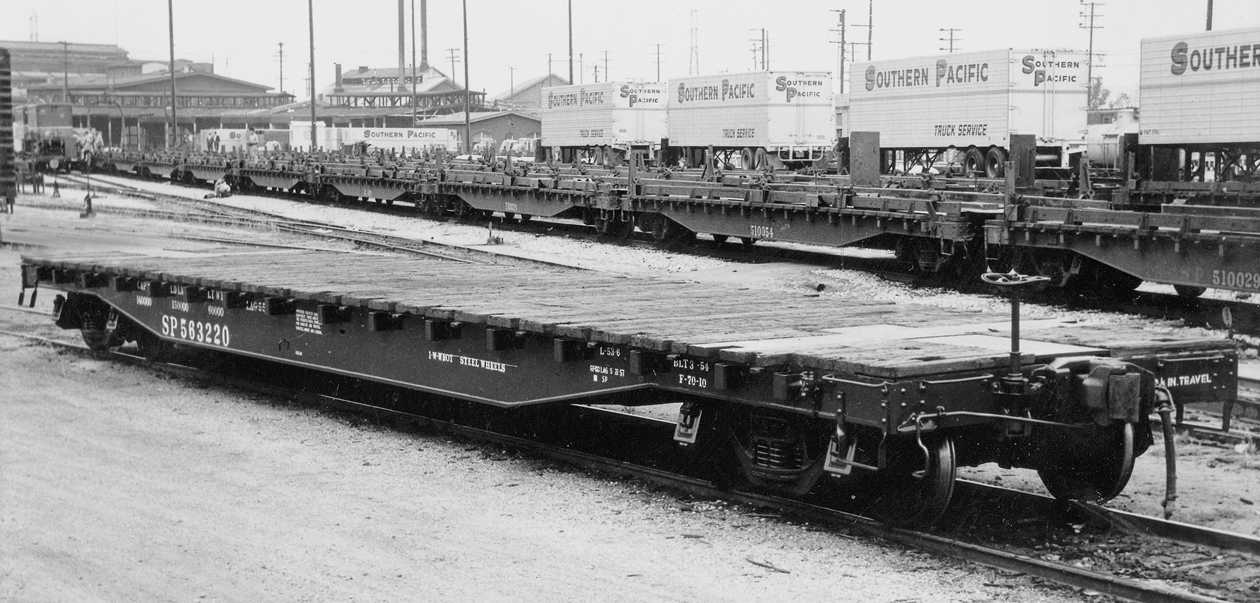
     Lastly, I should say a bit more about the F-50-10 class. Although, as I stated above, SP copied many features of the F-70-7 cars, they made one significant change. They lowered the sills, relative to the trucks, so that the deck could be flush with the top of the bolster. This meant that the top of the bolster and draft gear box were exposed on the deck. You can see this in the photo below (SP photo), showing car 563220, built as SP 143008. Again, you can click to enlarge.


This means that the F-70-7 and F-70-10 do not only differ by the presence of rivets in the former, but also in the deck. You cannot model a -10 car simply by shaving the rivets off of a -7 model.
     Another point about modeling is that you can fairly easily cut down a Class F-70-7 car to make a 40-foot car of Class F-50-16, but that’s a topic for a future post.
     My main point in this post is that the very important postwar SP flat cars, of classes F-70-6, F-70-7 and F-70-10, can readily be modeled with the various products of the SPH&TS. This includes not only the general service flat cars, but also the bulkhead cars and the piggyback cars. This is a major part of the SP transition-era flat car fleet and, as I said, essential for SP modelers of that era.
Tony Thompson

Saturday, September 1, 2018

Union Oil gas station, Part 3

I began this series of posts with background about Union Oil, including information about how its service stations looked, in the first post (you can see it at this link: http://modelingthesp.blogspot.com/2015/12/modeling-gas-station.html ). Then I began the modeling work of kitbashing a City Classics gas station kit, to fit the site on my layout. That post is available here: http://modelingthesp.blogspot.com/2018/08/union-oil-gas-station-part-2.html . In the present post, I continue with modeling.
     My first step in assembling the building was to glue the three “outside” walls, the front and both sides. These are the three sides represented as having the porcelain-enamel steel panels as sheathing, and thus the part that can receive a color stripe. After carefully filing away the draft angles on the sides and bottom of each wall, I glued them together with conventional styrene glue, making sure joints were thoroughly wet so they could be squeezed together and make a tight joint. I did this with a machinist’s square inside each corner, with the walls sitting vertically on a flat surface. This kept the bottom edges of all the wall pieces in a single plane.


The back wall, not shown, has also been cut down to fit into the shortened building, but I wanted to do the color stripe just on these parts, without having to mask or worry about the back wall, before inserting that wall.
     Meanwhile, of course, the kit base has to be adjusted in size to match the building. A concrete “pad” is pretty standard under service station buildings like this, even today, and this kit nicely indicates ramps into the service bays. This is the way to locate the cuts in the front part of the base, making sure the ramp lines up. A square cut and the usual glue procedure gives you the shortened front base.


     I used the excellent Tamiya masking tape to mask off the narrow panel above the windows on the station building (for more about Tamiya, see: http://modelingthesp.blogspot.com/2018/08/a-shout-out-for-tamiya-products.html ). This tape is very flexible and readily can be pressed down into narrow gaps or around protrusions. I then sprayed a deep orange, to reflect the usual Union Oil color. I considered a wider stripe, but decided this would suffice as an accent.


     Before going further with the building itself, I decided to make sure the site is all right. A key point with any commercial structure like this is that it sits at the height of the sidewalk, that is, above the curb height, rather than on the ground at road level. Below I show a photo of a service station near my home, to illustrate. The wide driveway has red-painted curbs at each edge, which helps them stand out.


The station shown above has concrete driveways and sidewalk, but is asphalt-paved inside the station, except for right between the pump islands. Other stations may have a complete concrete pad within the station property, like the one shown here. This curb is fairly low.


     To create a platform for this station, I used some sheet styrene, 1/16-inch thick. In HO scale, that’s a little under five and half inches, not a high curb. After looking carefully at the site, I decided to double this height by laminating another piece of the same styrene on top of it. I then marked about where the driveways ought to be, and began filing down the edges of the styrene in those locations to make the appropriate breaks in the curb line. Here is how it looked after a coat of primer:


     I will continue my description of modification and completion of this kit in future posts.
Tony Thompson