Showing posts with label Structures. Show all posts

Thursday, September 10, 2026

Modeling just part of an industry

There is a long-standing problem in building layouts, to achieve realistic depictions of industries. The problem is size. Many a layout contains buildings hardly larger than a boxcar , and that building is switched regularly, though a boxcar load of cargo could hardly even fit in the building. I too am guilty of this in a place or two on my layout.

The classic solution, and often a good one, is to represent any mammoth industry, steel mill or whatever, on the backdrop, as a group of flats or even just a photograph, and the switching for that industry is just a warehouse or shipping building. In such a case, the industry spur may run close to the backdrop, with just a flat photo or semi-3D building with doors. 

A good example of this kind of treatment was seen on a layout I visited during the 2023 “Great Lakes Getaway” in that year (for a description of the event, see: https://modelingthesp.blogspot.com/2023/11/the-2023-great-lakes-getaway.html ). The backdrop, literally of a steel mill, was on John DePauw’s immense EJ&E, set in 1973. Below is a view of his Kirk Yard in Gary, Indiana, with the very suitable mill backdrop. 

The industry, of course, need not be entirely in the distance, as is suggested by the above photo, served only by a delivery track or tracks. It can also be a flat of a specific building. I made several of these from the line of excellent KingMill backdrops of buildings, and used them several times for photo backdrops, as you see here. Even with its foamcore backing, it’s less than half an inch thick.

But if the industry in question is not quite so mammoth, we can choose to model just a three-dimensional shipping building, with the rest of the industry “elsewhere” off the layout. That was the approach I used for my Wine-Growers Cooperative facility in the layout town of Ballard. I built it so it would be just a warehouse and shipping facility, with the winery that actually produced the wine somewhere away from the railroad.

This industry is really two buildings, a large brick building imagined as the new part of the facility, and an older frame building with a shingle roof, a carryover from the original facility. The warehouse is for both aging and storage.

The brick warehouse is simply a Bristol board box covered with brick paper and three loading doors.  The frame part of the building was scratchbuilt and roofed with Campbell shingles. As shown below, I made an open loading platform so that I could include a workman handling a large wine barrel. Blending wine was still shipped in barrels to some extent in my era. (Be sure to choose barrels that would fit through the four-foot swing doors of the era’s reefers!)

I think that using this structure as just a shipping building helps its credibility, as it is really too small to be a realistic winery by itself (I have modeled a more credible-size building as my Zaca Mesa winery; see: https://modelingthesp.blogspot.com/2025/11/my-zaca-mesa-winery.html ). As I said above, it’s one way to deal with our usual over-compression of structures.

Nearly every layout can benefit from ways to represent larger industries than we have room to model in their entirety. What I’ve show here just scratches the surface. I used to keep notes when I saw a clever or especially effective way of doing this on layout visits. It’s one of the great benefits of such visits, one of the many things a visitor can learn from the imagination and work of others.

Tony Thompson

Sunday, August 23, 2026

My layout’s SP fuel and water storage

My layout, set in 1953, includes a modest engine terminal in the town of Shumala, with a turntable, two-stall roundhouse, and a sand house, along with water and oil columns for locomotive servicing. The columns, of course, are fed from storage tanks. The water is assumed to be provided by the town water system, but the fuel oil is brought in by tank car, thus there is a fuel spot to unload those cars. For more about the engine terminal itself, you may wish to look at my article in Model Railroad Hobbyist, August 2017.

The Shumala water tank is a Harriman standard design, imported years ago in brass by Overland. It’s shown below, painted black as was SP practice for steel tanks, alongside my Banta Model Works roundhouse. At the right edge of this view is the pump house for the water tank, an extra building from the Walthers oil dealer kit for McGraw Oil.

To make a storage tank for fuel oil (for SP, this was Bunker C, a viscous product that had to be heated to flow through piping to the firebox), I used an empty bottle of carpenter’s glue, with the top cut off, and with a wrapper of thin styrene with impressed rivet rows, to make a storage tank. I added a ladder to the tank top and an access hatch along with an SP medallion. The oil pump house is another building from McGraw Oil that I didn’t use with my Associated Oil model (see Model Railroad Hobbyist, March 2014).

The tank car you see above has the aluminum end stripe that SP used to designate cars assigned to diesel fuel service. In the foreground above, incidentally, is my scratchbuilt sand house, made following SP drawings for such buildings (see my article in Model Railroad Hobbyist, for January 2021).

To the right of the black fuel oil tank in the photo above is a smaller silver tank. This tank stores diesel fuel, with a clearer view of it below. I described building this tank, with color and label following an SP tank I photographed at West Oakland, in a previous blog post (you can find it at: https://modelingthesp.blogspot.com/2022/12/adding-storage-tanks.html ). 

The car at left below, probably delivering Bunker C fuel, is at the actual unloading spot. It is a generic black SP tank car, thus not in assigned service. The car is one of my several conversions of Athearn tank cars to accurate SP models. These Athearn conversions have been described in a full article about the process at: https://modelingthesp.blogspot.com/2011/05/modeling-sp-tank-cars.html ).

In addition to the end stripe on tank cars in diesel fuel service, there was also an all-aluminum scheme for this service, and in the early 1950s cars in both schemes were common. Here is an example of another Athearn conversion, lettered with the decal set I designed (now available from Tichy). This is the right side of the car, which correctly lacks dome walkway and grab iron.

In addition to providing a source for the fuel and water columns in the engine servicing area, the Bunker C and diesel fuel storage tanks are destinations for loaded tank cars, adding a little more switching around the engine terminal. Here’s an example waybill. Though SP mostly bought petroleum products from Chevron, they purchased from other oil companies also.

These parts of my engine terminal have worked out well. Though simple, they complete the logic of fuel and water supply, and as mentioned, are also an unloading destination. 

Tony Thompson 

Thursday, July 30, 2026

My lemon packing house

My layout is set in coastal California, and in the southern half of the state, such areas are suitable for lemon cultivation. Accordingly, I wanted to have a packing house for lemons. 

 In addition to the geographic suitability, there is an attractive traffic consequence, because lemons are harvested all year long. It is a commonplace observation that during most of the year, one can find blossoms, tiny green baby lemons, and ripe yellow lemons on lemon trees. Thus lemons are shipped year-round, rather than seasonally, as for most crops.

I described recently how I made my Zaca Mesa winery from a Magnuson kit structure (see the post at: https://modelingthesp.blogspot.com/2025/11/my-zaca-mesa-winery.html ). I show the kit box photos below for clarity. The major part of the structure became the winery, as described in the post cited, but the smaller receiving building, at right in the upper view below, became the lemon packing building. 

This brick structure had large arch openings at each end for hopper cars of coal. Since these made no sense in my intended use, I filled both arches with doors, first filling the curved part of the arch with brick paper. Below is the east end of the building as I modified it, which faces on Corralitos Lane. Note the smear of epoxy glue from the previous owner, which I tried and failed to remove.

At the west end, facing Laguna Street in my coastal town of Santa Rosalia, I instead modeled the doorway as a roll-up door, using corrugated metal and a half-round shape for the mechanism at top. 

A view of just the building on the layout shows a side view. I again added a roll-up door in the center, perhaps as a replacement for a deteriorated wooden door. I filled one window with brick, and the doorway at the right end is open, with some field boxes visible inside, containing lemons. I also added a couple of lemons on the ground, using craft beads.  At right is a truck picking up empty field boxes.

The building is on the small side for a packing house, but lemons require little work in packing, really only washing and grading, and putting into shipping boxes. Thus I believe that the building, though small, is just about big enough for credibility. I lettered it with dry transfers.

In use, you can see the two streets on either side of the building, as well as the layout surroundings, and a reefer being loaded. Street names are shown on the fascia. (You can click on the image to enlarge it if you wish.)

I enjoy having a citrus packing house on the layout, both for California flavor and for its year-round traffic. It exchanges loaded and empty reefers in nearly every operating session on the layout, regardless of the month of the session, just as it should.

Tony Thompson

Wednesday, January 29, 2025

Refining scenery, Part 5

This series of posts about minor scenery refinements on my layout is not intended to present profound insights into scenery development, only to illustrate that even a largely complete layout like mine can benefit from some refinement and upgrading of scenery. 

The present post is a follow-on to my post about creating some ground texture in an area alongside the modest-size industry, Pismo Marine Services, in my layout town of Santa Rosalia (read that post at: https://modelingthesp.blogspot.com/2025/01/refining-scenery-part-4.html ).

At the end of that prior post, I mentioned that I had chosen the Tichy handcar shed for a storage shed structure to be placed in the area I had worked on. Like most Tichy products, this shed goes together very nicely and is easy to build. The first step is to glue walls together and add the floor. (The building’s footprint in HO scale is 12 x 20 feet.)

Following this step, the doors were added. I decided to paint the roof of the structure a different color at this stage, when it is easy to do so. I chose dark green, a common enough color for rolled roofing as is depicted on this kit. 

And after considering several shades of gray and tan for the structure’s walls, I decided to keep the molded color of the walls, and thus simply sprayed the body with clear flat, so it could be weathered. I will paint the underfloor support posts a darker gray after weathering .

My next step was weathering. I used my usual technique, washes made with acrylic tube paint, as described in the “Reference pages” linked at the top right corner of this post. The intent was to show a moderate amount of dirt, consistent with a fairly long time in service. On the roof, I added some Pan Pastel gray to soften the dark green.

You can see above that the doors are a little elevated, to accommodate tracks for a speeder. But this isn’t going to be that kind of shed, so I needed to add a little platform, making shed entry convenient. I just used some scrap Evergreen scribed styrene sheet with about 10-scale-inch board width, and assembled it with styrene cement, using scale 8 x 8-inch strip for inside corner reinforcement. I then dirtied it with Pan Pastels. I also added the name of the adjoining business on the doors.

Next the ground texture and some grass and small vegetation needed to be added to complete the scene. That is why, in the previous post’s last photo (see link in top paragraph, above), the center of the area between the two dirt piles was unfinished. Now it looks like this.

Although really quite a small project, this does complete an essentially empty layout area that had been unscenicked except for painting the Homasote. The area has now been put to some use, instead of being merely a blank spot. I suspect there are lots of layouts with occasional small areas that could be given improvements or upgrades like this.

Tony Thompson


Friday, December 27, 2024

Refining scenery, Part 3

Back in the summer of 2024, I relocated the MP1 switch machines at the throat of my trackage into the layout town of Santa Rosalia. I won’t go into the reasons for that (it can all be found in a series of previous posts, culminating in this one: https://modelingthesp.blogspot.com/2024/07/update-on-switch-machine-installations.html ), but to sum up, the relocated machines had linkage exposed between machines and track. This can be seen below, along with remnants of previous arrangements. 

The “trenches” in which the linkages lie need to be filled in with paper mache, so they can be scenicked. The wire linkages pass through brass tubing, so filling the “trench” will only contact the tubing, and allow free movement of the linkage wire. In addition, the surrounding area was unfinished scenically, so that needed attention also. Below is an older photo of the entire area, as it appeared when the current structures were in place and the MP1 machines connections were concealed.

The building at photo center with the gray roof, built from a Timberline kit, is called “Ballard Farm Supply,”and is located here to cover the switch machines shown in the upper photo. To its right is a railroad water tank, and in the foreground is the Richfield bulk oil dealer in the town of Santa Rosalia, including a tank car spotted for unloading.

I applied Sculptamold paper mache to the linkage trenches, and also to make some ground contours in the area. As you can see below, this area is right in front of the backdrop, and some effort is needed to minimize visibility of the joint between horizontal layout surface and vertical backdrop. The loading dock in the photo below shows the location of the left end of the Ballard Farm Supply building.

Next the area needed to be painted. I used acrylic tube paint in Raw Umber for this. I extended the color over the entire area, since I want to scenick it all.

Next I applied my usual technique, a coating of matte medium followed by real dirt and a few pinches of Woodland Scenics grass. Then the area is spritzed with “wet water” to make sure the matte medium contacts all the scenic materials and secures them.

Finally, to show how this was supposed to end up, I show below the Ballard Farm Supply building in place to conceal the MP1 machines, though with its roof off. Other scenery work in the area remains to be done. Incidentally, the Farm Supply business does receive inbound rail shipments, but having no spur of its own, receives them at the town team track.

As I have observed in each of these “Refining Scenery” posts, this is a quite minor project, but I wanted to show it to illustrate the kind of thing that is often needed, even on a layout as nearly complete as mine. More later.

Tony Thompson

Saturday, August 24, 2024

Chromite ore shipments on my layout

 I’ve written several posts in the past about chromite mining in the area I model, the Central Coast of California. The first issue for me, and for anyone modeling a specific mining area, is to find out the prototype facts. I wrote a fairly general introduction about this, emphasizing how anyone could follow the kinds of leads I followed to learn about mining history in the area I model. That post is here: https://modelingthesp.blogspot.com/2016/10/modeling-mining-in-your-locale.html

I then wrote about modeling suitable ore cars, and suitable loads, to represent this ore traffic, in a Part 2 of the post just cited. In that post, I showed the crushed green shale I have used to represent a disseminated chromite ore (read it at: https://modelingthesp.blogspot.com/2016/10/modeling-mining-part-2.html ). This ore was too low of a grade to be used for refining to chromium metal or ferro-chrome alloying additives, and was typically used as a component in refractory brick.

In a third, more recent post, I repeated some of the background on chromite, and showed a few of the ore cars that I have placed in service. As I prefer to do in most of my open-top cars, the loads are removable. (See: https://modelingthesp.blogspot.com/2021/10/chromite-mining-on-my-layout.html .)

I was aware that by the 1950s most chromite mining in California was “pocket” mining on a small scale. I also faced the problem that there wasn’t space on the layout to install a mine scene. Solution? Assume ore is trucked from mine to rail. Then a truck dump would be the way that ore cars would be loaded, and this is also a compact kind of industry. 

I did have minimal space alongside Bromela Road in my town of Ballard, and built up a small incline that could perhaps serve as a truck dump. The truck helps identify what it is. The dump is by no means high enough to get close to direct dumping out of trucks into a railcar, so a conveyor would be needed.

So despite its obvious limitations, this preliminary attempt does suggest the activity. Then, in an operating session, a loaded ore car alongside the “dump” looks all right. A switch crew can pick up this car and understand its origin.

I have for some time kicked around ways to make this more realistic. A low truck incline is all right, if trucks can dump into a receiving bin, which in turn is emptied via conveyor into a railcar. But the space alongside Bromela Road is terribly narrow to model all that. Another possibility would be to load the ore cars at a team track, a logical place for truckloads of ore to arrive. Most of my team tracks have ample space to model a loading scene.

Note in the above photo that I show a GS (General Service) drop-bottom gondola being loaded. In one of my interviews with Mac Gaddis, he mentioned gondolas of actual chromite, a much denser material than the disseminated ore I am modeling. (See Mac’s comments at: http://modelingthesp.blogspot.com/2011/01/modeling-freight-traffic-coast-line_19.html .) But either ore could be loaded on my branch.

I am still toying with the idea of kitbashing the Walthers Truck Dump kit (their number 933-4058) into something I could use at a team track. I am a firm believer in Tony Koester’s admonition, “Don’t look at the name or picture on the box, just use the parts you need to make what you want” (from his fine book, How to Kitbash Structures, Kalmbach Books, 2012). If I get sufficiently inspired to do that, I’ll report on it in a future post.

Tony Thompson

Friday, July 5, 2024

An operating visit to the Salt Lake area

For almost 30 years, an operating weekend was held in the Salt Lake City area, called the “Great Basin Getaway” or GBG. In the last few years it has not been held, but last weekend a group of nine people, five of us from the Bay Area, made an informal visit, referred to as “GBG Lite.” Weather was fairly hot, but low humidity, and the air was gloriously clear, as it can be at the foot of the Wasatch. 

We operated on two excellent layouts, Rob Spangler’s 8th Subdivision of the Western Pacific, and Lee Nicholas’s Utah Colorado Western. I have said a bit about both layouts, in my description of the GBG event in 2016 (that post is at this link: https://modelingthesp.blogspot.com/2016/09/great-basin-getaway-2016.html ).

The first layout we operated was Spangler’s. As on my previous visit, I greatly admired his many excellent structures, fine backdrops, and impressive scenery treatments. Here is one of the structures that to me looked “just right,” at his town of Milton (note the “M” on the hillside in the background), a feed mill. The backdrop painting, for me, is a wonderful impressionist style, suggesting more than it shows.

An example of a fine scenic treatment is this depiction of a canyon, with one side of it shown only in part, but very convincing. I would say the same about the rock layers just visible on the hillsides.

One of the large industries is the Graymont facility at Lakeview, shown below. So often on model railroads our industries don’t look like they would need even one freight car for shipping, but this one certainly doesn’t fall into that error.

And just to the left of the above view was a nice treatment of a classic layout problem, how to handle a road that is heading directly into the backdrop. The Graymont sign in this view is right at the backdrop, so everything that looks like it is beyond the sign is just backdrop paint. And what nice mountains!

The second layout was Lee Nicholas’s well known and greatly respected Utah Colorado Western. I had really enjoyed operating here once before, and accordingly was really looking forward to another session. The train I drew was the CB&Q mine run, exchanging empties for loads at four coal mines. These were either facing point or trailing point switching, so planning was needed to do the work in most cases. Here’s one of those mines:

At the end of the run, all the (removable) loads were taken out of the cars in staging, and returned to all the empties that had been set out during the run. This of course set up the following session, when all that would be repeated. The actual operating plan was for me to run the train of (now) empty cars back over the entire route, so that the empty train would be at the original starting point.

But the way I was told that I now had the job of running the train in the opposite direction sounded to me like I was supposed to repeat the process: setting out empties and again picking up loads, just going in the opposite direction. This was actually pretty interesting, because the trailing point jobs in the original direction were now facing point, and vice versa. 

But as I neared the completion of this second run, I was told that no, I wasn’t supposed to repeat the switching, just run the empty train. But since I was now almost done, I finished up, and then went back, again replacing loads in the empty cars I had set out. I thought my version of the job was really better than the intended version! And Lee agreed with me, stating that my version of the job might become the new standard.

As before, I really enjoyed the finished scenery and many interesting and challenging industries all over the layout. And the backdrops are just as good. Here is the town of Cobre, with the depot at left, and my coal train on the main at the road crossing.

Another example of excellent scenic treatment is an even bigger challenge than the road heading into the backdrop: a road heading into a room corner. This adjoins the large (and impressive) sugar beet mill at Jiggs. The edge of the layout is about at the tall Texaco sign by the gas station. The road curving behind the store is entirely on the backdrop, painted on the coved corner.

It was a great weekend, operating on two great layouts. We all had a lot of fun, no surprise on layouts as good as these, and it most certainly was time well spent. Thanks again to Rob and Lee for hosting us!

Tony Thompson


Sunday, June 23, 2024

My engine servicing facilities

My layout of a fictitious Southern Pacific branch line was designed to have, as was SP practice, an engine terminal for the branch power. I have posted about my engine servicing facilities at the town of Shumala from the earliest days of this blog. For a look at those facilities in a fairly primitive state, see this post: https://modelingthesp.blogspot.com/2011/04/modeling-engine-terminal.html .

A few years later, I had built the excellent Banta Modelworks kit for the Port Costa SP roundhouse to go with my Diamond Scale turntable, and had added a caboose servicing building. I posted an update about the facilities to describe the changes; see: https://modelingthesp.blogspot.com/2016/01/shumala-engine-terminal-update.html

I also wrote an article for Model Railroad Hobbyist about engine servicing, which was in the issue for August 2017; that issue is still available to read on line or download, for free, at www.mrhmag.com . Many of my engine service details are shown in up-close views in that article.

Then two years ago, when I had increased the detailing around the fuel and water columns of the service area, and added a scratchbuilt sand house and refined other details, I posted another update (it’s available at: https://modelingthesp.blogspot.com/2022/01/modeling-engine-servicing.html ). Here’s a view looking across the turntable toward the roundhouse, with the caboose service track in the foreground.

One relatively new feature in these facilities is a storage tank for diesel fuel. Since a diesel switcher is normally used at Shumala, this would be expected. I’ve now added it. It’s the silver tank shown below, just to the left of the sand house (the turntable pit is in the foreground). The large black tank is for steam locomotive Bunker C oil. In front of the tank are duckboards (see: https://modelingthesp.blogspot.com/2015/08/duckboards.html ).

Some time back I added a kind of “mini-scene” on a stub track off the turntable, to illustrate changing out a wheelset in a freight truck. This was part of another Model Railroad Hobbyist article about prototype trucks and wheels, in September 2016; this one too is still available for free.

In the view below, the scene shows a new wheelset being rolled into position to be placed in the truck. The removed wheelsets, with shiny wheel treads, are already moved out of the way. In the left background are shown a couple of truck bolsters and a stack of side frames (note the prototypical small kingpin center holes in the bolsters). This was set up temporarily, to photograph for the article, but I liked it and have left it in place.

Lastly, the track that you see just above the wheelset scene (above) is a track that serves the machine shop on the back of the roundhouse (see: https://modelingthesp.blogspot.com/2016/03/a-shop-track-for-shumala.html ). This allows me to set up varying scenes of parts deliveries to the roundhouse; machinery deliveries to the shop; inbound or outbound loads of wheels; and other interesting scenes. 

Here’s a load of new wheels arriving in a gondola, presumably for the roundhouse machine shop to complete wheel tread contours and press onto axles.

Another possibility (to choose just one alternative for illustration) is unloading something like machine tools from a flat car, at the machine shop loading dock. That’s shown below, and as with the scenes shown above, is readily changed. I originally tried to show a tarpaulin partly off one of the machines, but couldn’t make it look right to my eyes. (You can click on the image to enlarge it.)

All in all, I feel like my engine terminal facilities are complete at this point, and they serve what is needed as I wanted them to do.

Tony Thompson

Wednesday, May 15, 2024

Understanding bridges, Part 3: Details

The two preceding posts in this series attempted to provide a broad background for bridge design and appearance, including references, concentrating on the prototype for each of several types of bridges. You can read the second post (and find a link to the first one) at this link: https://modelingthesp.blogspot.com/2024/03/understanding-bridges-part-2.html . The present post presents some important bridge details that should be included if you are building a model. 

An example of such details is the bridge shoe. This is the support on which a bridge member actually rests. Modelers sometimes make the mistake of simply resting a girder bridge or truss bridge directly on its abutment. Here’s an example (I’d rather not identify the layout on which this was found.)

The prototype has shoes at each end, one of them fixed (though able to rotate about a horizontal axis perpendicular to the long axis of the bridge), and a moveable shoe that can slide, to accommodate expansion and contraction. 

Here is a drawing from the Mallery book (Paul Mallery, Bridge and Trestle Handbook, revised edition, Boynton and Associates, 1976), Chapter 6. Mallery correctly points out that bridge shoes on all but the biggest bridges are so small in HO scale that we needn’t differentiate between the fixed and moveable shoes, which at any distance look quite similar. This one is a moveable shoe.

Here is a different model example of a girder bridge, correctly including a bridge shoe, which appears to be a fixed shoe.

Another clear example, from the late Bill Neill’s excellent layout in the Detroit area, is part of his model of the Pennsylvania’s massive truss bridge over the Ohio River at Wheeling. This is a really large shoe for a large bridge.
The abutments at the ends of bridges vary considerably in design, and may be built with a wide variety of materials, often concrete in the modern age. Naturally an abutment rises to the height of the track, and has an inset at the level of the bottom of the bridge member, where the shoe rests (as in the model deck girder above). This may be the full width of the abutment, or may be quite a bit less, especially when the abutment has wings to support the underlying fill at that point. The stone abutment shown below is from the Southern Pacific steel trestle at Gaviota, California (the shoe isn’t visible from this angle).

Another important point is bridge “floors.” Many bridges have no actual floor, and the structural members of the bridge are visible between the ties. Here is another drawing from the Mallery book, Chapter 9, showing the names of members in a through-girder bridge, including the floor members: beams, stringers and diagonal (lateral) braces. 

My original bridge over Chamisal Road on my layout was designed from this drawing, with full floor members. But the girders were far too deep, as I showed in a post when I was beginning work on a replacement bridge (see that post at: https://modelingthesp.blogspot.com/2013/05/a-new-sp-bridge-for-shumala.html ). I used Mallery’s book to choose realistic girder proportions, and then scratch-built new girders of correct size. 

In the process, I also changed the bridge design, in that SP predominantly designed and built ballasted-deck bridges. My new bridge was designed that way too, so that the floor structure is hidden (shown in this post: https://modelingthesp.blogspot.com/2013/09/a-new-sp-bridge-for-shumala-part-3.html ). Of course, the floor members are still present underneath a ballasted deck, but the location of this particular bridge on the layout prevents any possibility that the underside of the bridge can be seen, so I omitted it.

Information about prototype bridges and bridge details is quite readily available, if modelers would only consult it. For a serious modeler, there is really no excuse for not including prototype bridge features and details.

Tony Thompson

Monday, March 25, 2024

SoundRail 2024

In alternate years, the layout owners around Puget Sound, Washington put together an operating weekend called, for obvious reasons, SoundRail. I attended this years, as I have done four previous SoundRails. I’ve always liked their emblem, combining rail with the waters of the Sound and Seattle’s iconic “Space Needle,” dating from the 1962 World's Fair.

This year, my layout assignments began with Joe Greene, located way up in Sequim, on the upper edge of the Olympic Peninsula. This is a wonderful layout, modeling the C&O in Appalachia in 1974. The job I drew this time was the excellent paper mill model, with (I think) 16 different car spots around the plant. This was interesting and fun! Mark Schutzer and I had a great time switching the entire area, along with some yard work.

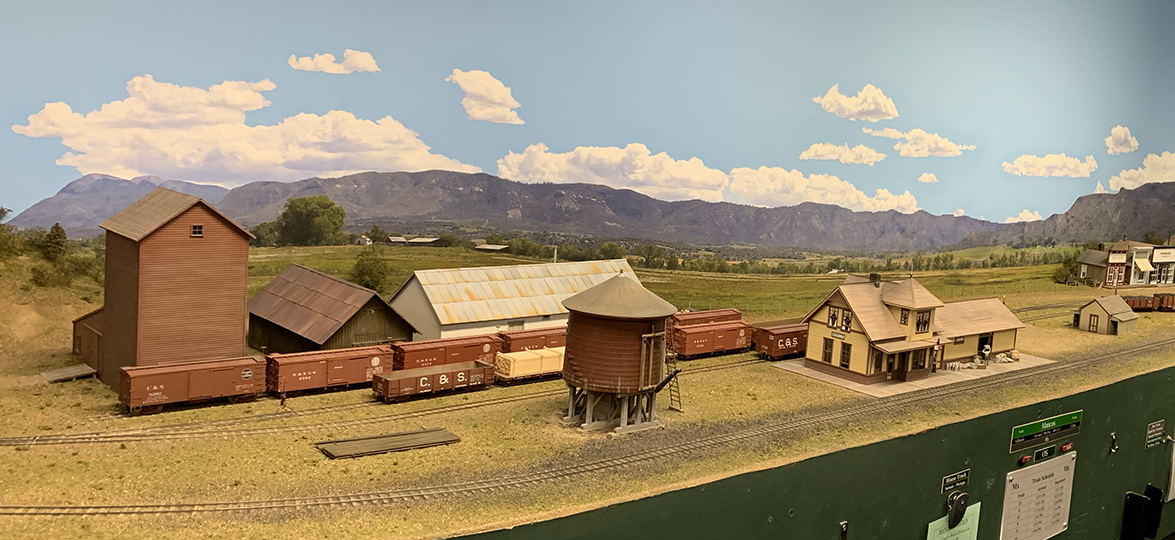
The following day, we began the regular schedule of the meet (Joe’s layout was a “bonus” session). My first layout was Dale Kreutzer’s superb Rio Grande Southern 2nd District, set in 1926. I had operated there once before, so knew what to expect. It’s a marvelous job of scenery, the trains ran perfectly, and it was really a pleasure. I had the Mancos Turn, a switching-intensive assignment that was excellent for me, and much of the enjoyment was the beautiful setting.

Next came Bill Sornsin’s Great Northern, modeling the Seattle area and the eastward climb to the top of the Cascades in 1956 in HO scale. I was really looking forward to this, as I had not operated at Bill’s at the previous SoundRail, and was eager to see layout progress. There was a lot! He now has a magnificent model of King Street station, an iconic structure and of course the centerpiece of extensive passenger operation.

I got to work at Interbay Yard, which had only limited operating capability last time I was there, but now was a fully functioning yard, closely following the prototype trackage. The yard crew really had fun all day here. And the prototype yard is still there today, not far from Bill’s home.

My final layout was Jim Younkins’ N-scale Mud Bay & Southern, set in the Olympia area in 1974. This is a huge layout, with very nice scenery and excellent structures. One of the things I like about N scale is that industries can be big enough to look like they really need multiple freight car spots. My job this time (my third visit!) was at Elma, a location with a lot of switching. Here’s a view of North Elma, with the yard area in the foreground.

One of the many nice features of Jim’s layout for visitors is the excellent town maps on the fascia in each area. Here is the map for the scene shown above. (You can click on the image to enlarge it if you wish.)

This was another outstanding SoundRail, a meet I have enjoyed every time I have attended, and I’m sure I will go back. I report all this mostly to show how much interesting fun you can have at a meet like this, and I hope anyone reading this, who hasn’t every operated at such a meet, will seek one out and give it a try.

Tony Thompson