Saturday, March 30, 2013

Streets, roads, and all that, Part 2

In my first post about various aspects of streets and roads (see: http://modelingthesp.blogspot.com/2013/03/streets-roads-and-all-that.html ), I described some signage and my approach to center lines, all to improve the realism of roads on the layout. In this second post, I take up some associated topics.
    Grade crossings. A roadway subject which can get complicated is that of grade crossing warnings. Here again, there are state and federal highway standards, which are in fact quite informative. A useful web version of these is: http://safety.fhwa.dot.gov/xings/com_roaduser/07010/sec04a.htm . [You need to scroll about halfway down the document to get to the meat.] Some of these standards would not apply to 1953, but the basic ones certainly do. It should be noted that the railroad, not the local road authority, was responsible for providing, erecting, and maintaining crossbucks.
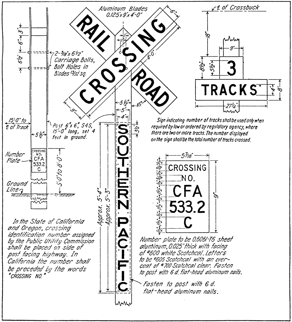
     To sum up briefly, crossbucks are to be placed essentially “at” the crossing (warning you to slow down, look, and listen), with an added sign for multiple tracks. The SP drawing (see below for reference) directs use of 6 x 6-inch timber posts, 15 feet long, set four feet in the ground, location to be 15 feet from centerline of track. Lettering is 6-inch Egyptian. Like many railroads, SP placed the two crossed boards on opposite sides of the post. In addition, there were railroads which did not place the crossbuck boards at 90 degrees to each other, but SP did.
     Shown below is a portion of Southern Pacific Common Standard 1320 (formerly CS 13), a drawing created in 1904 and updated to 1970, by which time the signboards themselves had become aluminum plate. In 1953, these were all wood. The drawing can be found in Southern Pacific Lines Common Standard Plans, Volume II (Steam Age Equipment Co., Dunsmuir, CA, 1993), page 8. You may click on the drawing to enlarge. 


I have put the full drawing on Google Drive, which you can access (and download and print, if you wish). It is available at the following link: https://docs.google.com/file/d/0Bz_ctrHrDz4wenJwS0ViMHJrZjQ/edit?usp=sharing .
     I have used both styrene and metal (NJ International) crossbucks in HO scale. Recently Microscale has produced a decal set (No. 87-1376) with the vertical lettering “Southern Pacific,” which SP placed on some posts of crossbucks, as the drawing above indicates. Note also the black tar preservative at post bottom, to be used on all white posts, to 6 inches above ground.


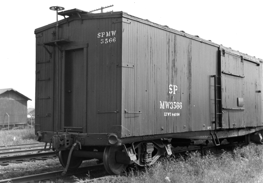
I took the photo above near Monterey, CA in January 1980. Now, 1980 is long after my 1953 modeling date, but the same appearance is appropriate for my era, as is shown by this 1953 image at San Luis Obispo, a detail of a photo taken by Richard Steinheimer, from the DeGolyer Library (used with permission). Note the 1953 license plates on cars. Also notice the round sign at far right.


The San Luis Obispo signs (the one on the far side of the tracks is also visible at left), protecting the crossing at Osos Street, do not have the vertical lettering. In the full CS 1320 drawing, SP specified that this lettering was only to be used at major highways or in large incorporated cities, neither of which will apply in most places on my layout.
     A closely related sign is the required round, yellow “advance warning” sign (I showed an example of the current version in the previous post on this topic: http://modelingthesp.blogspot.com/2013/03/streets-roads-and-all-that.html ), normally not less than 100 feet from the crossing, but other locations can be used when sight lines are restricted or physical conditions at the crossing would prevent that length of warning distance. These are the responsibility of the local road authority, not the railroad.
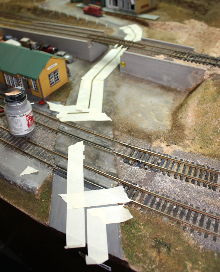
     Today’s warning sign has diagonal lines with “R R” on either side. In 1953, this arrangement was in the process of superseding an older style with vertical and horizontal lines, and “R R” at the top—see the San Luis Obispo view above. Here is the one I have on Chamisal Road, at lower right (the photo is from my old layout, and the bridge has girders which are too deep and are being replaced), for a track just beyond the underpass.


The older style sign is offered in HO by Tichy, their part number TIC 8177.
     License plates. Roads, of course, are used by motor vehicles, and I have posted previously about my approach to vehicle license plates which are correct for the era modeled (California in 1953). There were two posts about this, and they contain considerably more detail than I can re-visit here. They can be viewed at the following links. I covered automobile license plates at: http://modelingthesp.blogspot.com/2012/11/vehicle-license-plates-in-ho-scale.html , and then described California licenses for highway trucks, in this post: http://modelingthesp.blogspot.com/2012/12/vehicle-license-plates-trucks.html .
     These various street-related topics strike me as part of the fun of researching the era one models, and of course getting the right appearance helps set the stage on which you depict your era.
Tony Thompson

Wednesday, March 27, 2013

Modeling some SP MOW cars

All railroads maintained a fleet of cars used in various non-revenue work, from wreck trains and shop cars, to work trains and supply trains. Most of these were simply older cars removed from revenue service, and modified when necessary for their new duties. Others might be bought new, such as wreck cranes, or used unmodified, as in the case of box cars used for trackwork supplies or the like.
     For many railroads, this “shadow fleet” of cars remains undocumented, with only occasional photographs providing evidence of what once was. For other roads, including the Southern Pacific, extensive records do exist of car conversions, car uses, and appearance. Those records include extensive car ledgers and car cards at the California State Railroad Museum (CSRM) in Sacramento.
     Some readers of this blog may already know that Ken Harrison has been at work for some years, collecting information on SP’s maintenance fleet, including close examination of the records at CSRM, and hopes to eventually create a book from the material. In the meantime, however, we can work with other, readily available sources.
     The Southern Pacific Historical & Technical Society in past years sold a Xeroxed copy of 1956 rosters for freight, passenger, and maintenance rolling stock (entitled “Southern Pacific Car Roster as of January 31, 1956”). It was more than 300 pages, plastic-bound, and not terribly expensive. It is the maintenance part of that car roster that I refer to in this post.
     Although the Society has not stocked this book over the last few years, they have just reprinted a few copies this month. Try the on-line store within the SPH&TS web site, at http://www.sphtsstore.org/servlet/the-92/Southern-Pacific-Car-Roster/Detail , to see if it is in stock. If not, you might wish to email your interest to the Society at: sphts@sphts.org.
     I show below a sample page from this document, to illustrate how informative and helpful it is. Note that this is page 44 of the maintenance roster; that roster alone (less than a third of the entire SPH&TS book) has 99 pages altogether.


     With this roster as a starting point, I have pursued creating a few reasonably accurate cars for my own fleet. The most obvious candidates for simple modeling projects are those cars which were not visibly modified. Among these are what SP called “roadway box” and “roadway flat” cars. These were used in their original configuration for simple carrying of materials and equipment.
     For example, by the time I model, 1953, the Harriman box cars of classes B-50-1, -2 and -4 were gone from revenue service, but there is a fine Westerfield kit, No. 1751, for this car (and this can be an excuse to build some of the nice kits out there for older cars!). All I needed to do was to search through the SPH&TS roster book for roadway-service cars formerly of this class, and choose a number. You can see in the page shown above that such a car is present, SPMW 2621, a former Class B-50-2 car which had been converted to MOW service on February 23, 1943.


The simplified lettering is typical of SPMW equipment. I used pieces of Microscale set 87-155, including the “Danger” lettering at right.
     Here is a prototype photo of a similar Harriman box car in MW service (though this one has a side ladder and an end door). The photo is from the Arnold Menke collection, location and photographer unknown. Note that the only item of capacity or dimensional data is the light weight. The SPH&TS roster shows that this is a former B-50-2 car, number 89084, converted on December 30, 1944.


     Another common car in work trains is a tank car for domestic water. SP used lots of its old tank cars this way, particularly the very durable steel cars of classes CS-25A, O-50-1 and O-50-2. As it happens, Westside imported a very well done CS-25A tank car, which they advertised as a crude oil car and labeled on the box as “tank car 1905,” an imaginary name; these cars were actually built in 1903. Moreover, they were neither built exclusively for nor at all limited to crude oil transportation. Here is a photo of one in work service in the 1950s, from the Steve Peery collection.


     My Westside model was lettered from the same Microscale set mentioned above, 87-155. Most MW water cars were in the low 7400-series numbers (and are included in the SPH&TS roster book). The lettering was either in the first panel near the end, or the panel next to it. Here is how my model looks; it still has its diagonal hold-downs, which the prototype shown above did not. Prototype car SPMW 7424 was originally SP 51625, converted on April 9, 1936.


Incidentally, you can find much more information about both these tank cars, and cars like the Harriman box car shown above, in my volumes, Southern Pacific Freight Cars, Volume 4 on box cars, and Volume 5 on tank cars and hoppers. Both are from Signature Press, published in 2006 and 2008, respectively.
     These two cars are a start on the subject of modeling SPMW equipment. I will put together a second post to cover more of them.
Tony Thompson

Tuesday, March 26, 2013

RPM-East, and a correction

Last Thursday through Sunday I was in the Pittsburgh, PA area, to attend the 2013 meeting of RPM-East, a meeting which is held in the Pittsburgh and Philadelphia areas in alternate years. I was there primarily to give two talks and have a chance to see old friends from my own days in Pittsburgh, and I also had the chance to operate on Larry Kline’s large O scale layout. For those interested, RPM-East has a nice website, maintained by Eric Hansmann, at: http://www.hansmanns.org/rpm_east/ .
     One embarrassing moment at the event was the revelation by Eric Thur that I had credited him with models at the Cocoa Beach meeting (last January) that actually were not his. If you go to the post about those models (see: http://modelingthesp.blogspot.com/2013/02/prototype-rails-at-cocoa-beach-2013.html ), the first photo in the post does indeed show Eric’s models, but the following photo does not show Eric’s models—they are John Johnson’s. As I have known Johnny Johnson for many years, this is doubly embarrassing for me, and I apologize not only to Johnny but to anyone else who didn’t realize who was the right person to credit for the fine modeling shown. I have edited that post to correct the text, but wanted to also mention it here.
     Let me return to Larry Kline’s layout. Here is a photo of his yard and engine house mockup at Western Maryland’s Bowest, PA. In the background is Larry’s mockup of parts of the National Tube Works at McKeesport.


Naturally Bowest usually contains lots of WM hoppers, loaded and empty, as is obvious in this view of part of the yard. That’s WM Baldwin switcher 129 at the left, and part of P&LE’s Dickerson Run yard in the right background.


He also has a staging yard at the other side of the basement from Bowest, called Ridgeley Yard, where mostly steam-powered WM trains are ready for action, heading west to Bowest. That handsome B&O Pacific nearest the turntable was scratchbuilt by Herman Kloppenburg for the late Warren Mayfield, and Larry has upgraded some details as well as adding DCC. Those happen to be NCE throttles lying on the layout, and packets of car cards can be seen ahead of staged trains.


We all took turn running trains between the various interchange yards (Rook Yard of the P&WV, Dickerson Run for the P&LE, and Bowest), and here is a shot of me switching at Bowest. Judging by my level of concentration, I must have been dealing with a very complex set of moves! (This photo was taken by Jim Ruffing, who was among the operators that night.)


       The trip to RPM-East was fun for me. The meeting was interesting and I enjoyed a chance to run trains on Larry’s layout. Thanks again, Larry.
Tony Thompson

Friday, March 22, 2013

Streets, roads, and all that

The area I model is far from urban, though not quite country. So most of my roads are pretty simple; many are even without a center line. Of course there is more to the “street scene” than the center line, but I will begin there. Before starting, I should mention that Jack Burgess, in his “Getting Real” column for November 2011 in Model Railroad Hobbyist, touched briefly on some of these same topics. (You can download that or any copy of MRH for free at their website, http://model-railroad-hobbyist.com/magazine .)
     Center Lines. The first thing I had to recognize was that in 1953, when I model, California used only white for center lines of roads. There are numerous sources on the web for information about standards such as these. Jack Burgess, a retired city engineer, directed me to several of these. Some are pretty technical; the most informative ones were a Wikipedia entry, at http://en.wikipedia.org/wiki/Road_surface_marking , and a more detailed one with information about the MUTCD (Manual on Uniform Traffic Control Devices), in use nationally since 1935 and widely used by traffic engineers, at: https://ceprofs.civil.tamu.edu/ghawkins/MUTCD-History_files/MarkingColorEvolution.pdf .
     The standard for most classes of roads was stripes 4 to 6 inches wide, and 15 feet long, with 25-foot gaps between stripes. No doubt these standards are for higher road speeds. I have reduced these dimensions somewhat so my relatively small layout roads look okay. A couple of my roads from the old layout had yellow center lines, so these were re-masked to be repainted.
     My procedure was to lay out the lines using drafting tape (much preferable to masking tape, as it has distinctly less “tack”).


My first cut at this used pure white, but this looked far too clean, so I tried Floquil “SP Lettering Gray,” a rather light gray, and it worked much better. I did dry-brush it with some white acrylic paint to lighten it toward the front of the layout. Here is an overhead view of the result, along with some oil stains and tar patches.


     Warning signs. California used red for boulevard stop signs in 1953 and in fact had done so since the 1920s. Some states still had yellow stop signs in 1953, but not California (you can research the state you model to find out what you need to do). My boulevard stops are mounted on scale 4 x 4-inch white posts (see below). This photo was also used in a previous post about signs (at: http://modelingthesp.blogspot.com/2013/02/signs-for-structures.html ).


     Roads should also have diamond-shaped warning signs as needed, for example indicating sharp curves. I do have a need for such a sign on Chamisal Road at Shumala, as is evident from photos of this road, such as the one above. Here are some standard yellow warning signs of the kind that I mean.


The railroad crossing warning sign at right is really associated with crossbucks, and as that topic has some complications, discussion of the round “RR” warning sign will be deferred to a future post which will cover crossbucks also.
     Street signs. Another subject worth exploring is street signs, even at intersections for country roads. Accordingly, I have also been adding street signs to road corners on the layout. At the intersection next to the store at Shumala, for example, the paved Chamisal Road bends toward the backdrop, while the dirt road which runs alongside the railroad tracks is called Railroad Avenue (there is a similarly located Railroad Avenue in nearby Oceano). I simply printed out these names on glossy paper using a high-resolution printer, and mounted them to a scale 4 x 4-inch styrene or wood post. Here is the sign for an intersection on the Shumala extension.


     Crossbucks. The signs warning motorists at railroad crossings, both crossbucks and other signs, ought to be very visible alongside our tracks. As mentioned, I will discuss them at some length in my next post on this topic.
     In this post I have talked about road center lines, and the various warning and other street signs, which are definitely needed for realistic roads on the layout; after all, practically everyone is a motorist, and we not only know but expect these typical accompaniments of the roadside. This is just one of many details which are essential to convey the reality that you are trying to depict on your layout.
Tony Thompson

Tuesday, March 19, 2013

Shumala’s extension, Part 5 — painting the sky

Many modelers think of the sky portion of a backdrop as just a blue color of some kind, which then receives a skyline of mountains, hills, forests, dwellings, and so on. But the sky is an important component. It is a kind of background, to be sure, but should still look realistic. My opinion is that except on very clear and bright days, the sky blue lightens toward the horizon, due to haze and dust, and the backdrop should reflect this. Clouds, if any, are an additional topic. California skies in much of the year are close to cloud-free, though near-coastal areas can have a marine layer of low clouds from spring to fall.
     This post follows on from the prior posts, first about blending an old backdrop onto the wall above my layout extension at Shumala (see: http://modelingthesp.blogspot.com/2013/03/the-shumala-extension-part-3-backdrop.html ), and then about softening a room corner by giving it a radius (see: http://modelingthesp.blogspot.com/2013/03/shumalas-extension-part-4-handling.html ).
     One can reproduce a sky color gradient with a single blue, with increasing additions of white at lower levels. Alternatively, one can choose a range of blue colors from a commercial palette. I chose to use three Pratt & Lambert colors to blend vertically in my sky painting. That paint company was not chosen for some particular paint quality, but because they offer small sample containers, so that paint colors can be tried out. My darkest blue, for the uppermost part of the backdrop, was “Capri Grotto,” their number 25-7. The medium blue, next down form the top, was “October Sky,” number 25-4, and the lightest was “Andover,” number 25-1. That these are all in the P&L “25” series shows that they have a base color in common, but become lighter with lower numbers. This is common in paint company palettes, and is worth looking for in selecting paint.
     My first step was to use blue painter’s tape to set the edges of what I wanted to paint above the extension. These were checked with a level to make sure they would be vertical at one edge, and elsewhere parallel to the base and to the existing backdrop. Of course these could be aligned however you want, but I wanted a level top.


Once that was done, I painted a primer coat using the medium blue of my three colors, as you can see here.


When the blue primer was complete, it looked like this.


     Next I needed to do the blending, top to bottom. I not only used my three shades of blue, listed above, but also mixed in old coffee cans, mixtures of half and half dark and medium blue, and medium and light blue. Using five colors total may be overkill, especially since this latex paint dries fairly quickly and the idea of “blending while wet” really can’t be accomplished. Anyway, here is how the blended sky looked, after removing the painter’s tape but before doing any clouds or land profiles.


     That should be enough to describe my basic sky. I will probably work to blend a little better once all the paint is thoroughly dry and has attained its final darkness of color (these three blues do change quite a bit between wet and dry). Adding any clouds, perhaps a marine fog layer, and profiles of background hills is more of an “art” challenge, and I will describe that in a future post.
Tony Thompson

Sunday, March 17, 2013

Vegetation communities as a guide to scenery

Many parts of the United States have relatively uniform communities of natural vegetation which extend for miles. Even some mountainous areas exhibit consistent vegetation over a wide region. But as in so many other ways, California is different. In numerous parts of the state, distinct vegetation communities thrive in close proximity, often due in large part to microclimates, which in turn can be a dominant influence in Mediterranean climates like California’s. Understanding these considerations is of obvious importance in creating realistic layout scenery.
     As with other posts I have written, I recognize that the specifics of what I discuss here applies to my layout and few others. What I hope to demonstrate is an approach to learning about and applying knowledge of landscapes.
     An epiphany moment for my understanding of this topic, as a native Californian and one who has lived in the state for many years, was reading Elna Bakker’s book, An Island Called California, 2nd Edition (University of California Press, 1984). She describes with knowledgeable enthusiasm the many variations in vegetation communities (and the ecological consequences of them) which can be found in California. I had been seeing much of this landscape for years without understanding what I saw, and again and again, I would read a section of the book exclaiming to myself, “yes, of course, I’ve seen exactly that.”
     I will just give a couple of examples that apply to my layout. The most familiar California landscape probably is the oak woodland, meaning grasslands with scattered oak trees, usually valley oaks (quercus lobata, the largest of America’s oaks) but sometimes live oaks (such as the coastal live oak, quercus agrifolia). The area I model contains some areas of oak woodland, such this example near Santa Maria.


In hilly areas, the oaks (and some accompanying chaparral) tend to concentrate near stream beds and lower areas where water availability is greater. This results in a distinctive landscape also, with drier slopes mostly grassland.


Most of the importance of knowing how these communities look is for my layout backdrops, which attempt to reproduce these kinds of appearance.
     Near the ocean, outside the immediate beach area, many parts of California exhibit “coastal sage,” a community which often looks like brushy chaparral but comprises smaller plants, and different ones. Here is an example of this landscape, near the area I model. You can see the ocean in the left background, and the SP main line in the middle distance.


In this case, the vegetation is summer brown (photo taken in September), but the same area would be a dark green in spring when rainfall has been occurring.
     I have attempted to model this community on my layout, at the end of the peninsula above the beach scene. It’s shown in one of my posts about layout fascia, available at: http://modelingthesp.blogspot.com/2013/02/layout-fascia-my-approach.html .
     California’s wild grasses have a seasonal progression which often confuses people from other places. The grasses have to sprout new growth whenever rain starts, so the hillsides and fields start to green up in late November or early December, which is a typical time for the rainy season to start. Then rains will arrive irregularly through about the end of March or mid-April, and grasses remain green throughout that time and of course increase gradually in height. Then once rain is no longer arriving, the grasses go dormant and begin to turn straw color (often called “golden” by the romantically inclined), and by late summer, more of a pale brown color. Both the second and third photos in this post show that late-season brownish color.
     But in amongst most grassy areas are annual weeds of other kinds, some of which can remain green all summer. So although entire hillsides of uniformly colored grass certainly exist, local areas may be more mixed. This photo of a bank just north of the depot in San Luis Obispo, taken in August 1981, shows what I mean.


The grass here is not exceptionally high (nor is it on most hillsides), so despite the understandable enthusiasm of some modelers of midwestern and other seasonal grasses, to use very tall electrostatic grass in natural areas, that is really not very typical of California.
     This discussion of California seasonal grass, like that on vegetation communities, obviously only applies for modelers recreating that specific vegetation community. But I expanded on it to illustrate that one needs to understand what is going on in the landscapes you model.
Tony Thompson

Wednesday, March 13, 2013

Shumala’s extension, Part 4 — handling a corner

In the previous post about progress on the Shumala extension (see: http://modelingthesp.blogspot.com/2013/03/the-shumala-extension-part-3-backdrop.html ), I described re-attaching an old piece of painted backdrop to blend the new area to the old. There is a second backdrop issue, which is the fact that the Shumala extension location is the room corner at its left end. It looked like this:


     In many cases, one would cove more Masonite around this corner to conceal it. But in this particular location, there isn’t a lot of space; it isn’t entirely necessary (as I will show); and might well be more work than it is worth. Accordingly, I resorted to an old trick: just make a small-radius curve in the corner. Even a one-inch strip of, say, styrene set at a 45-degree angle would greatly soften the right-angle corner, but with drywall joint compound, one can form a smooth curve. To fill most of the corner, I took a 3/4-inch square garden stake and used a carpenter’s chisel split it into two 45-degree pieces:


The resulting two pieces are set with their 90-degree corners into the room corner, using drywall compound as an adhesive. In the photo below, I am filling the rough corners in a first coat. The corner modification is only as high as the backdrop elsewhere.


Then with successive coats, the entire corner can be faired into a smooth curve. I used a flour scoop made from a tin can, about 2.5 inches in diameter, to smooth the final contour. A larger can might work a bit better, but note that removing one end of the can eliminates the rim and permits the smooth length of the can to do its job. The scoop can be seen in the left foreground below. The rounded corner extends about 40 percent of the visible corner height.


Once several coats have been applied and sanded smooth, the corner almost disappears. I believe the key to how this works is that your eye no longer has a sharp edge to focus on, thus doesn’t focus on the corner, which of course is the point.
     Painting the sky and horizon line come next and will be shown in a future post.
Tony Thompson

Sunday, March 10, 2013

Winterail 2013

Yesterday, March 9, was the date of this year’s Winterail “Railroad Photography Exposition,” held once again in Stockton, California. The site was the Scottish Rite Masonic Center in Stockton. I won’t offer a general description of Winterail, as I have posted that last year (you can see that post at: http://modelingthesp.blogspot.com/2012/03/winterail.html ). But this was a little different, as it was the 35th consecutive year of Winterail, and there were many comments and back-pats on that score. There was even a modified version of the traditional emblem, on the program and on T-shirts:


     But most of the meeting was what it traditionally always is: a morning railroadiana show and sales event, and afternoon and evening photo presentations, which for many years have been utterly impressive and professional. The doors open at 9 AM, and there is always a line-up of the “early birds” waiting for admission, seen here across the patio between the two wings of the building.


Once inside, everyone heads for the display rooms, and there is everything from books, photos and timetables to clothing, railroad china and other artifacts, sometimes very large ones like semaphore signals. Much of the circulating crowd in the rooms is greeting friends and chatting, so this is often the core of the social side of Winterail, along with shopping and purchasing that special item.


There is a food concession, offering barbeque and other things off the grill, and many attendees take coffee breaks and lunch in the patio. The patio was pleasantly sunny as it usually is, though this year the air was fairly cool.


The Stockton Masonic Center includes a large auditorium, holding about a thousand people, and most years it is pretty full for the photo show. Here is a view of the crowd, taken from the floor down in front.


The auditorium is fairly steeply sloped, and provides a good view from every seat, as is evident in this view from partway up the far right-hand aisle. The screen is properly large and entirely appropriate for the photo presentations.


There is a two-hour break for dinner. For many years a sizable group went to a sort of steak house called The Shadows, but it has now gone out of business. This year eight of us repaired to a pleasant brew pub named Valley Brew, and enjoyed a good meal. Here is Ray deBlieck (left) apparently struggling to count the money, while Ed Slintak at right checks Ray’s calculation of the bill. That’s Eric Dervinis at far right.


All in all, a fine day of railroad topics, information and friends, as is entirely usual with Winterail.
Tony Thompson

Thursday, March 7, 2013

The Shumala extension, Part 3 — backdrop

In previous posts about this layout extension, I described the construction of the simple benchwork atop a bookcase, including Homasote surfacing (see: http://modelingthesp.blogspot.com/2012/11/the-shumala-extension.html ), followed by describing the preparation of trackwork and some preliminary landform profiling (see: http://modelingthesp.blogspot.com/2013/01/the-shumala-extension-part-2.html ).
     In this post I address the preparation of a backdrop for the extension. There was an existing piece of backdrop salvaged from my old layout in Pittsburgh, PA, which I believed could be curved and used to connect the existing Shumala backdrop to the extension (that was its role in the old layout). This is how the area looked at this point:


The clamps visible here are my adding some glue to the joint between the existing backdrop and its support post, prior to attaching the new section. The Shumala extension is at the left. In the right foreground you can see the turntable and what will be the roundhouse area. The mainline connection to my staging table curves rightward through the middle distance.
     I knew I would need two pairs of hands to set the backdrop in place and get screws in place to hold it. My friend Ray deBlieck came over to lend those hands. Here I am installing the last drywall screws once we had it in place, with Ray at left.


At the left edge, the backdrop does not quite come parallel to the wall, as is obvious in the photo above.
     Although this backdrop segment was previously joined to the main Shumala backdrop, it did not fit perfectly, and the overlap, originally created with fiberglass mesh and drywall joint compound, stuck up. Here is the new segment in place, with the sticking-up joint obvious at right. But the continuity in the painted image is evident. Note also the new hole in the bottom of this backdrop, at ground level, to clear the mainline trackage, next to the portable drill.


     That imperfect joint at the right was glued down and repaired with more drywall compound. At the left edge, where the backdrop is not quite tangent to the wall, some blending is necessary. Here the solution I used is the fiberglass mesh, sometimes called “wall repair tape,” which is sold for drywall joints and patches. I have used it before, and know that when embedded in drywall compound, it works very well to prevent cracking. Then it’s a matter of successive coats of drywall compound, sanding for smoothness between each (short description of a sometimes lengthy process). Here it is when that process was done.


Next comes painting a coat of primer on the drywall compound areas.
     I will show touching up the paint and the repainting the backdrop in a future post. I will also show how I handled the room corner to the left of the photos above.
Tony Thompson

Monday, March 4, 2013

Kitbashing a background structure

When Heljan, the Danish model railroad manufacturer, released a whole group of Ford Museum models back in the 1980s, one especially caught my eye: a version of the original Ford Motor Company office building (kit 912). Here is a photo of how the model was supposed to look, as seen in the foreground.


     This building was not exactly what I had in mind. I needed a background structure at Ballard, and I liked the regular arrangement of large windows in this frame building for a manufacturing business, but wanted a different-shaped building. So I set out to “cut and paste,” if you will, and create something entirely new.
     First of all, I wanted a less “stubby” building, and since I was aiming at a background structure, I could use both kit walls to make one side longer. Not visible in the view of the kit, above, is a loading door on the other side, and I wanted to include this for rail service. And the building seemed to sit a little low on the ground, so I raised it up on some 1/4-inch Plastruct rectangular tubing.
     Here is a view of the back of the main wall, to show where I spliced pieces together to get a longer building with the proportions I wanted (arrows indicate line of joints). I spliced in a three-window section, so the two-story part is now seven windows long instead of four. You can see my splice plates at the joints, and the added foundation tubing also (click to enlarge if you wish).


And to make the building even longer, I built an addition, using the single-story rear part of the other side. Here is the back of that addition, which is elevated with the same Plastruct tubing foundation.


I wanted some rooftop machinery, so built a little styrene box, added a piece of diesel locomotive grille, and made ducts from pieces of styrene sprue. You can see the back of the box above; the photo below shows it from the front of this part. You can also see how the structure was tapered to fit my background space.


It’s evident here that I retained the as-molded light-gray plastic of the kit windows and doors, but painted the structure a pale bluish-green. It has also been weathered with some streaks from window corners and other features. Note that I painted the foundation tubing a tan concrete color
     When arranged as they are on the layout, the two parts look like this. You can see here the adjustments made to the roof to accommodate the taper of both parts of the building, which of course fits the layout site. A small loading dock is needed by the freight door at the re-entrant angle in the structure.


     Since the structure is back from the layout edge, I made a billboard-type sign, and added (non-operating) floodlights to illuminate it.


This industry was inspired by a Consolidated Aircraft company facility at the old Grand Central airport in Glendale, California, which I remember from my youth. The Grand Central airport terminal building, constructed in 1928, is still standing today (owned by the Walt Disney Company), but the airport closed in 1959. A number of movies were filmed there when it was still an airport, and many aviation businesses began there in the early days. I assume that Consolidated company was different than the one which merged in 1941 to form Convair. There is a nice Wikipedia entry about Grand Central for anyone interested.
     The sign I made lists three plant locations, to suggest that this particular facility has siblings. (“Glendale” gets a little bolder lettering to suggest that the main company facility is there.) Consolidated manufactured, among other things, aviation electronics, so I imagine that being done at this company division. The name? Could refer to electronics for night flying, I suppose, but might also suggest that it’s kind of a fly-by-night outfit.
     The Nocturnal Aviation structure is visible in many of my layout photos at Ballard, for example this one. I placed black construction paper inside the building as a view block for the many windows.


     As with a number of the model projects I have described in my blog posts, the point is not to suggest that anyone else necessarily would want to duplicate what I did, but to show the approach and the results, hopefully to encourage a creative approach to kits, and experimentation with them, by others.
Tony Thompson

Saturday, March 2, 2013

Layout fascia, Part 2 -- signage

     My first post about layout fascia described my approach to this feature, using tempered Masonite in its natural color. You can read that discussion at: http://modelingthesp.blogspot.com/2013/02/layout-fascia-my-approach.html . In this post I want to address signage.
     This is an important point about layout fascia appearance, though only adopted by some modelers, and is something I myself learned from C.J. Riley. (This point is made in his forthcoming book, The Art of Illusion, which describes ways to create the illusion that we model real places.) On the prototype, almost every location has a name, and this can be conveyed on the fascia with small nameplates. This would apply to things which intersect the plane of the fascia, like creeks, roads or other features, as well as railroad crossings. Town names are also useful to display, as are directions such as East and West, because visitors usually do not have a clear understanding of the layout orientation or locations.
     Before describing the signs themselves, let me say a few words about choices of place names on a layout set in an entirely real geographic area but not modeling actual towns. It seems to me the names chosen ought to be consistent with the history and character of the area, as evident from existing place names and other sources.
     For my own signs, I began with maps, first a detailed road map of the area, a Rand McNally county map for San Luis Obispo County. To that I added the two USGS quadrangles which cover the area modeled, the Oceano and Guadalupe (California) quadrangles from the 7.5-minute topographic series. These different maps complement each other, because the road map shows all street names in built-up areas, which the quadrangles do not, but the topo maps are very thorough about names of geographic features such as creeks, valleys and hills.
     Because I like to understand where words come from, when I can, I studied the area place names extensively in a great reference book for Californians, California Place Names, 3rd Edition, by Edwin Gudde (University of California Press, Berkeley and Los Angeles, 1969). I will refer further to this below. Now let’s turn to the signs themselves.
     I chose a typeface for these signs which I thought had a lively character without being ornate or eye-catching. The face is called Hamilton. [I will digress briefly about the typeface – if not interested, skip to the next paragraph.] Hamilton was named for William Hamilton Page (1829–1906), a self-taught designer of wood types, who patented this face in 1887. Although Page called it “#508,” when it was digitized by Font Bureau in 1993, they called it Hamilton in his honor. In 1891, Page sold his company to the Hamilton Company (no relation) of Wisconsin. Many original Hamilton wood types are preserved at the Hamilton Wood Type & Printing Museum in Two Rivers, Wisconsin. Though they are currently in the process of moving to a new location, if you’re interested you can find out more about them at their web site: http://woodtype.org/ .
     I experimented with type sizes to find a fascia sign size I liked. There is of course no universal answer on this point; the lettering size I chose is about 3/16-inch (4 mm) high. The lettering then needs to be placed on a standard width of these nameplates. To harmonize with the type size, I have chosen 3/8-inch wide, with length to suit the name.
     I have printed out the nameplates on glossy cardstock, using a laser printer. They can then receive a coat of Dullcoat or other lacquer to protect them. I usually attach them with a water-base glue, such as white glue or model airplane canopy glue, because if they need to be removed, they can simply be wetted and left until the glue softens.
     Here is a photo of two of them, as applied. I chose to position the bottom of each label 1.25 inches below the top of the fascia. I have taped a steel straightedge at that distance to make placement of the signs easy (and level). This view pretty much looks right up Nipomo Street. The depressed location of the creek bed is naturally reflected in a cut-out in the fascia profile. The fascia here is a narrow strip of tempered Masonite.
 

What you see below the fascia is the staging table, which I have described previously. For a link to part of my description of this feature, see: http://modelingthesp.blogspot.com/2011/02/staging-trackage-installation-4.html .
     Oso Flaco Creek, shown above, is a real creek in the area modeled, and has a number of upstream branches. The name in Spanish means “skinny bear,” and the name was applied by the soldiers of the Portolá expedition, who camped in this area in September 1769, and who killed such a bear near their camp. Nipomo Street is named for the nearby town of Nipomo, a Chumash Indian place name for one of their villages. Oddly, the present town of Nipomo has no street by that name. I could hardly resist the fact that there is a Thompson Avenue in Nipomo, but it is some ways from the railroad location and in any event is a north-south road.
     At Shumala, a road runs right past the depot and under the bridge which carries the branch line inland. Its name is Chamisal Road.


The name refers to the original Spanish land grant in this area, Rancho Bolsa Chamisal, with the word “bolsa” for the land areas which are largely surrounded by swamps or water. The word “chamisal” in pre-American days simply meant chaparral. Like the other research findings, this one is really applicable only on my layout, but I wanted to illustrate the process of arriving at these names.
     Finally, I mentioned including town names and directional information in my introduction to this post. I am not yet completely satisfied with my design for this type of sign, but here is the current iteration.


     These examples could be multiplied, but I hope the point is made. Labeling features that reach the fascia, like water courses and roads, along with town names, helps visitors know where they are. And if you do not model an exact location, research via maps and books can tell you what kind of names you should choose.
Tony Thompson