Monday, October 29, 2012

Upgrading old models -- not always

I have been asked if I try and upgrade all my older models. (I realize the question may have been somewhat tongue-in-cheek . . . ) The answer is certainly “no,” because a fair number get replaced by a more correct or better detailed version of the same car. For example, I used to have a stand-in model for the important D&RGW box car series, numbers 66000–67499, a single-sheathed and distinctive car that was a mainstay of the Rio Grande boxcar fleet until after World War II.
     The stand-in was a Train Miniature box car, with lots of detail shortcomings as well as inaccuracies relative to the D&RGW prototype, but with largely correct decal lettering. It really wouldn’t be possible to upgrade it without practically starting over, and I’ve sold it off. The replacement? The Westerfield kit for this car, kit no. 6453, which is accurate and very well detailed (this kit remains available from the new owner of Westerfield Models, Andrew Dahm, at his web site: http://westerfieldmodels.com/ ).


This model was built by Dennis Williams and decaled and weathered by me.
     There are other examples of cars which really are not candidates to save, as the bodies are simply too far from accurate to try and modify. One example is the old AHM six-dome tank car. The design folks who worked on this one must have started from a photo of a smaller car, and just inflated the tank part (perhaps with air pressure!) until it was large enough for their 40-foot underframe — or large enough to “look good,” as one designer for a major manufacturer once said to me. But the car is over 12,000 gallons in size and is far larger than any prototype car of this type ever found.


There is no answer for this one but to discard it. I sold off a couple of these that I had, but did keep one for my display case, where I have a collection of oddball cars that are fun to look at. These do surface at swap meets, and I can only counsel resistance to any impulse purchase.
     Another such model, and one unfortunately still very much available commercially, is the by-now very old Athearn three-dome tank car. Although not at all badly done for its era, in its detail and overall realistic look, it is again simply way oversize. Despite years of searching, no one has ever found a prototype three-dome car as big as this. Here is one of these models, with a bogus paint scheme to go with the bogus body (Union only ever painted a car with this blue and orange scheme when a car was donated to a museum).


As some readers of this blog may recall, I do use Athearn three-dome bodies as sacrifice sources of extra dome tops to increase dome height, as I showed in my post about making a correct SP tank car. (You can view it at: http://modelingthesp.blogspot.com/2011/05/modeling-sp-tank-cars.html .) But as an operating model? Nope.
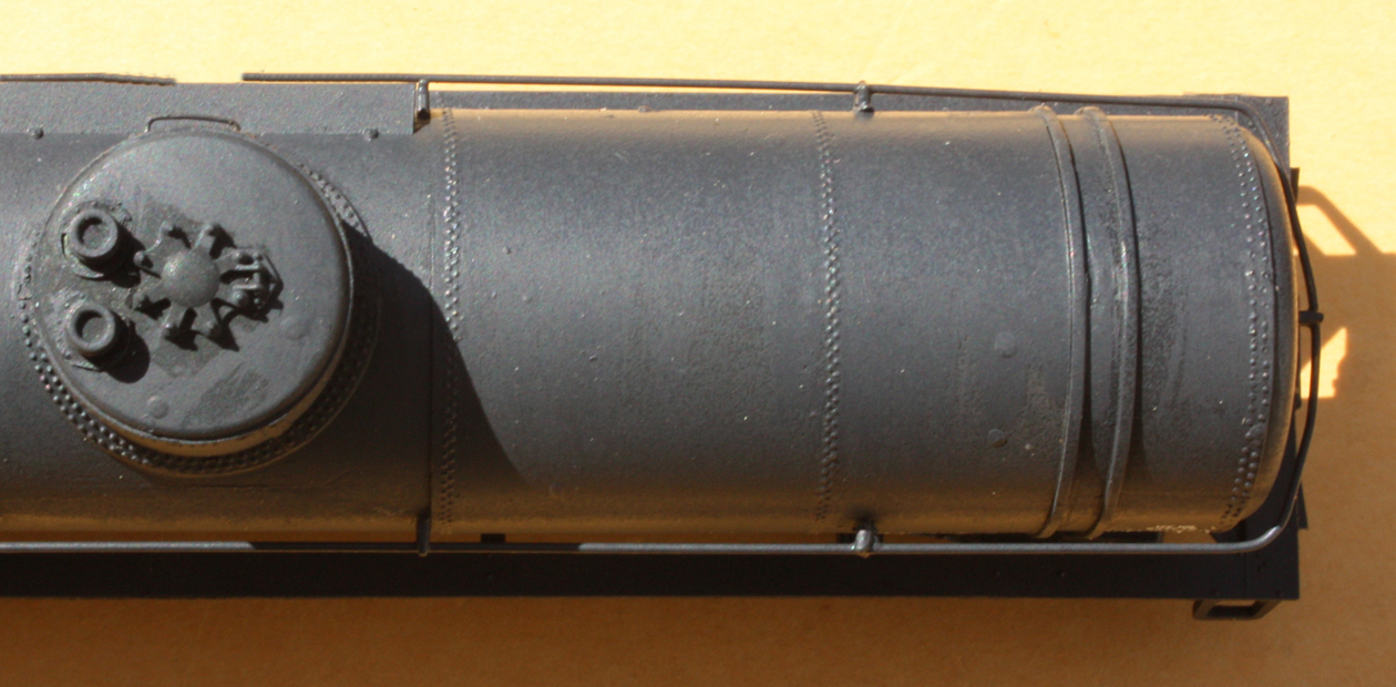
     One more example. Back in the day when HO scale had very few tank car models of any kind, one tended to keep almost anything, just for variety. But some of those oldies are now being discarded. An example is this LifeLike tank car (a copy of an older Varney product). In past years, I added brake gear and new trucks and couplers, repainted it, and then lettered the car with decals for UTLX. And one other improvement I’ve made to cars of this heritage, the dome-top modification described in a previous post, can be viewed at: http://modelingthesp.blogspot.com/2010/12/upgrading-old-models-3.html .


     So what’s wrong with it, even with the changes I’ve already made? Long list. The vertical brake wheel stand is a very unusual arrangement; the sill steps are crude and the walkway terribly thick (and a poor representation of a metal-grid walkway); the handrail supports are crude and unprototypical; there is no side ladder on either side; the dome-top manway cover is a strange and oversize arrangement; there is a ridge along the tank top, instead of the correct double row of rivets where tank sheets overlap; the end head is an odd shape; and the rivets representing the attachment of the head to the tank are far too far apart. I could go on, but you get the idea.
     Are these defects correctible? Most are, but there are so many. And at the end of the day you would arrive at an 11,000-gallon tank car, pretty big for the steam era. I am not upgrading these Varney/LifeLike/Walthers tank car models except for a very few, kept mostly for nostalgia reasons.
     So that’s it. I definitely have had and still have models on hand, that just cannot justify being upgraded. They not only need replacement for accuracy and detailing, but at present cannot even serve in mainline trains, under my existing standards. Many are already gone; the rest will follow.
Tony Thompson

Saturday, October 27, 2012

SP Society convention, 2012

The annual convention of the SP Historical & Technical Society was held this year in Ventura, California, on October 10–13. The Society’s own website (at http://www.sphts.org/ ) will eventually have photographic coverage of much of the event, including our fine train ride on the Fillmore & Western, though several aspects, like the clinic program, cannot really be covered photographically (I gave one of the talks, and the handout for it was posted via this link: http://modelingthesp.blogspot.com/2012/10/ventura-pfe-talk-handout.html ). There would ordinarily also be coverage of the prize-winning models in the Trainline magazine next January. So between other coverage and the wide range of activities, I won’t try to summarize anything but the model display.
     I didn’t try to photograph the entire room, but just wanted to show representative views. One major feature of nearly all our conventions is the “Wall of Trains,” a display which permits long trains to be displayed in their entirety. The convention theme was the Coast Route’s “Overnight” train, so a couple of models of “Overnight” trains are visible here.


     On the table below the “Wall” were displayed additional entries of entire trains. One was my entry of a transition-era SP freight train, behind Consolidation SP 2763. I always put out slips by each car to indicate what the prototype is, and how the model originated. It’s the second train from the front, 14 cars and a caboose.


Among the fine dioramas displayed was one by Andrew Merriam, of the sand house and sand tower at San Luis Obispo. I really liked the realistic structures and setting.


Another favorite area for many people at the convention is the always-extensive array of locomotive model entries. Here is a snapshot of just some of the fine steam and diesel power entered.


Last, I will show one of the freight cars displayed, Dick Harley’s fine job of modeling a PFE R-70-13 from the Red Caboose kit, involving a new roof and narrowed door. Dick also presented an excellent double clinic about PFE’s mechanical reefer fleet.


     With all these fine models, and many more, on display, it’s understandable that the model room is thronged with viewers all the hours it’s open. It has long been, and continues to be, one of the highlights of each SPH&TS convention.
Tony Thompson

Tuesday, October 23, 2012

Naperville tank car handout -- Part 2

I received some comments after my two oral presentations at Naperville, and via e-mail subsequently, that a couple of parts of the handout material were not very clear. With that in mind, I intend to add a couple of short text summaries to supplement what was provided in the first two pages of the “bare bones” handout. The handout itself can be viewed via this link: http://modelingthesp.blogspot.com/2012/10/naperville-tank-car-handout.html .
     One area of confusion was my formula for calculating tank car volumes. Nowadays, model manufacturers largely follow actual prototypes for tank cars, and the volume stated in the product name, such as 10,000 gallons, is pretty dependable. But in earlier days, that was rarely true, and a number of manufacturers appear to have simply cobbled up something that looked good to them. So a way to measure a model and know its gallonage seemed like a good idea.
     The problem, of course, is that although a tank car is essentially a cylinder, it has domed heads of a complex contour, and hardly anybody is eager to do the geometrical analysis, followed by the algebra, needed to mathematically describe such a volume accurately. Instead, I sought for a simplification that would give a good approximation.
     Before going further, I should mention the dome. It was there to accommodate expansion of the cargo in many tank cars. But it was normally empty. In fact, the convention in loading transition-era and earlier tank cars was to load them “shell full,” which meant filling the liquid just to the top of the horizontal cylindrical tank. This is easy to judge visually, and when a tank was shell-full, it contained the number of gallons stenciled on the car end.
     Tank car cargoes were almost always billed by gallonage, not by weight, so the exact gallon capacity had to be on the end of the car. In fact, that gallon capacity was in a way similar to the light weight of a box car – it might not be the same for any two cars, but was essential to billing cargoes. So the dome size is not part of the tank car capacity. Expansion domes, however, were required to be a minimum of 2 percent of the tank capacity (or the capacity of the compartment, in multiple-compartment cars).
     Anyway, returning to the tank volume calculation, the main cylinder is easy, since we all learned the formula for volume of a cylinder in high school. But you need to recognize where to measure. Here is my crude sketch, and the associated formula:


So with measurements over the cylindrical segments, L or H, with measurements in scale inches, one obtains the volume in cubic inches.
     Now of course we have neglected those pesky tank heads (or the dome top). The key point in my method is to try and find an adjustment or “fudge” factor which would correct for those omissions. Here is what I found. Using a conversion of cubic inches to gallons of 225, that is, assuming 225 cubic inches per gallon, gave excellent agreement on prototype tank car volumes (I will document that statement in a moment).  In other words, divide your calculated cubic inches by 225 to obtain tank gallonage. The handbook value is 231 cubic inches per gallon, so the difference of a few percent accounts for tank head shape, etc.
     Here’s my documentation that it works. The following table contains both prototype and model tank gallonages; the prototype values in the right-hand column were calculated from tank car drawing dimensions (D and L) in Car Builders Cyclopedia volumes, for cars of the nominal gallonage listed in the left-hand column. It can be seen that the agreement is good, which was the basis for deriving the 225 conversion factor. I don’t show dome volumes in this table, but dimensions are given for anyone wanting to calculate them.
     As for the model dimensions, note that a lot of older tank car models are pretty big. Only the Athearn model, clearly based on the SP prototype tank car of 12,500 gallons, is really an accurate size. But newer ones, like Red Caboose and Tichy models, would be expected to be accurate, and are indeed so.


This table is also in the handout previously mentioned, but its origins and use were not explained.
     I hope this clarifies the volume measurements, which can be done in any scale for any kind of tank car.
Tony Thompson

Friday, October 19, 2012

Naperville tank car handout

I prepared only an abbreviated handout on paper for my talk on “Modeling Transition-era Tank Cars,” presented at the Naperville, Illinois meeting of Railroad Prototype Modelers, October 18–20, 2012. That abbreviated, two-page text has been combined with additional modeling notes, and two pages of prototype photos of the tank cars described in the talk, to make the document now available at Google Drive (formerly Google Docs). Here is the link for anyone interested in downloading this document:

https://docs.google.com/file/d/0Bz_ctrHrDz4wdEZJRWFKVTZhVUk/edit

Hopefully this is helpful information to summarize and encapsulate my presentation at Naperville.
Tony Thompson

Thursday, October 18, 2012

Modeling SP tank cars-4: circumferential rivets

In this post, I want to complete the description of an additional SP tank car project. The basics of converting an Athearn tank car to SP prototype are entirely the same as in my article from the SP Historical & Technical Society magazine, Trainline, issue 71, and updated in an earlier blog post, at: http://modelingthesp.blogspot.com/2011/05/modeling-sp-tank-cars.html. This post is about completing the car with circumferential instead of longitudinal rivet rows, which I introduced in a post about tank sheets of this type, at: http://modelingthesp.blogspot.com/2011/06/modeling-sp-tank-cars-3-tank-sheets.html . The tank car in question is the one with Archer rivets.
     The underframe work was my standard procedure with Athearn tank cars: to remove the triple-compartment outlets, separate the coupler box covers so they can be attached with screws, and use the Athearn brakewheel stand to fill the hole into which it fits, then cut it off flush. Finally, brake rodding is added (I used Plastruct styrene rod in the 0.010-inch size), along with the piping from the valve to the cylinder, the only really visible piping on a car like this.  For details, see the article first cited above.
     One easy refinement is to use the Tichy ratchet and pawl for the handbrake staff, a part included in their Tank Car Detail Set, part no. 3007. It is shown below on the Athearn end sill (arrowed). You can click on this image to enlarge it.


Here you can see the white Plastruct brake rods and the brass wire pipe to the cylinder. I also have filled the ladder holes in the running board on the right side, where there will be no ladder. The same Tichy set includes a nice brake wheel, which I attached to a brass wire staff of 0.019-inch diameter.
     Body work included adding brass wire grab irons at all four corners of the tank, and one grab on the side of the dome which has the dome walk. I normally use 0.012-inch brass wire for this. I then made a new handrail, all one piece, using brass wire of 0.022-inch diameter. The original Athearn pieces make a good pattern to work from. The correct size would be 0.019-inch wire, corresponding to the outside diameter of the 1.25-inch pipe used for handrails, but it is preferable to the half-handrails of roughly 0.023-inch steel wire supplied by Athearn.
     The virtue of the one-piece handrail is evident in this view of the non-dome-walk side. Note here that the handrail supports have not yet been added on the overlay sections of the tank. After this photo, I simply harvested these from scrap Athearn tank car bodies, and applied them to this tank with Plastruct’s very effective “Plastic Weld” solvent cement.


Note that with the clear styrene overlays, the former locations where outboard domes were cut away on the Athearn triple-compartment model can be seen. The Archer rivets have been applied.
     My next step was to airbrush the car with a lightened black color, which helps later when weathering is being applied. I keep on my paint shelf a mix of Floquil colors, mostly black but with some white and brown, which I sometimes use for tank cars, but for this one I just sprayed it with Grimy Black. At this point, it is easier to appreciate the refinement of the Archer rivets.


     This car was easy to letter because I had made up SP tank car decals last year (this was described in an earlier post on that topic, at: http://modelingthesp.blogspot.com/2011/05/sp-tank-car-decals.html ). There were only two SP tank car classes with both dome-top safety valves and circumferential tank sheets, classes O-50-10 and O-50-11, and I had already modeled a car of Class O-50-10, so this one ought to be an O-50-11. (The reader of my Volume 5 with a retentive memory may recall Class O-50-7, which did indeed have both this type of safety valve and these tank sheets, but it was a car with a shorter and fatter tank, and can’t be modeled with an Athearn tank car.)
     Here is the completed car, using a pre-1946 lettering scheme (tank cars were not repainted as often as most other freight cars).


     This was an interesting project, just as a way to see how Archer rivets would work for this kind of tank car. And this sort of modeling was exactly what I had in mind when I researched the rivet size and spacing for Archer to produce their set no. AR88031 (that set is shown in the Tank Sheet post, cited second at the top of this post). I’m glad to see it all come together.
Tony Thompson

Monday, October 15, 2012

Ventura PFE talk handout

At the recently concluded Annual Convention of the Southern Pacific Historical & Technical Society, at Ventura, California on October 10–13, I presented a talk entitled “PFE Traffic on SP’s Coast Line.” I did not prepare a paper handout for the talk, but instead announced that a handout, in PDF format, would be available in a blog post here. That is now available on Google Drive (formerly Google Docs), and here is the link:

https://docs.google.com/file/d/0Bz_ctrHrDz4wMWFRb1BXWVdwZ1E/edit

This summarizes the traffic side of the talk. Anyone with questions beyond what is in the handout, please contact me directly, or comment on this post.
Tony Thompson

Sunday, October 14, 2012

Modeling SP passenger cars, Part 2: head-end cars

Head-end cars are all the non-passenger-carrying cars seen at the head end of passenger trains: baggage and postal cars handling mail and express, and some other cargoes. Some trains might include express refrigerator cars. In the AAR classification, these would be baggage-express cars (Class BE), baggage-horse cars (BH), express refrigerator (BR), and box express (BX) cars in the non-mail categories, and then full postal (Class MA), postal storage (MR), and postal-baggage (MB) cars. As I briefly mentioned in my introductory post on this topic (it is available at this link: http://modelingthesp.blogspot.com/2012/10/choosing-model-sp-passenger-cars.html ), all these car types could be found in the “Coast Mail,” trains 71 and 72.
     Before going any further, I should mention the absolutely essential information contained in the monumental volume on these types of cars, published by the SP Historical & Technical Society, Volume 3 in the series Southern Pacific Passenger Cars, and subtitled “Head-end Equipment” (SPH&TS, Pasadena, CA, 2007). This is simply the bible on this topic, and much that I say in this and following posts about head-end cars relies entirely on its foundation.
     As is true for other parts of its fleet of rolling stock, SP’s head-end cars comprise a pretty complicated story when told in full (see Volume 3, cited above). But for modeling purposes, we can simplify it considerably. One simplification is to discuss only the 60-foot and 70-foot baggage cars, most of them arch-roof cars (I will return in a later post to the 80-foot baggage-horse cars), and postal cars.
     I will begin with the 60-foot baggage cars. There has long been in HO scale a kind of approximation to these cars, the old Model Die Casting baggage car. It is not terribly accurate in several details, and suffers from the defect of the entire MDC arch-roof passenger car series: rivets the scale size of grapefruits. Although I once worked to improve one of these cars for layout service, including sanding off the roof rivets, I eventually abandoned the project and sold the model. But I do believe these can be reworked sufficiently to serve, amongst better baggage cars. I just don’t own an example.
     Another long-serving source of these cars is the old Ken Kidder brass model. The Kidder models also have a few discrepancies from the SP prototype baggage cars, and were originally sold with no underbody equipment at all. But most of the appearance is all right for SP, and underbody detail is readily added. Over the years, I have picked up several of these cars. They are certainly not great models, but aside from the too-low roof arch, they are really pretty decent overall.
     The prototype underbody is typified by a battery box on one side only, with one of the brake system reservoirs visible on the other side (and an electrical generator, if one had been fitted). What I mean is clearly shown by these two views of SP 6018, taken at Fresno in April 1958 (used here by courtesy of the photographer, Don Munger). First, what in freight car parlance would be the left side. This is SP Class 60-B-3, with all 12 SP cars in the class built in 1910.


And as a comparison, the other or right side; note the battery box:


These two photos are on page 237 of the SPH&TS book, Volume 3. Note also that the end nearest the camera is lettered “BAGGAGE” on both sides.
     These cars were delivered with steel baggage doors, but most cars in later years had paneled wood doors, as in the photos above. The original configuration of vents and other equipment on the roof varied according to how and when the car had been shopped, though most of these cars did retain their Globe vents, as above.
     Here is one of my Kidder cars, lettered with Thin Film “Harriman” decals (set HO-160). Their catalog is at: http://thinfilmdecals.com/ . The battery box is on the far side.


     The 70-foot baggage cars are also distinctive, particularly the ones with windows, and years ago, when there were essentially no alternatives, I kitbashed a couple of them out of Athearn plastic baggage cars. I wrote up the process in some detail for Prototype Modeler magazine (Vol. 7, No. 6, March-April 1984, pages 39–44). What I obtained was one car with correct windows and reasonable looking doors and other details, and a second car which really wasn't too accurate but was at least a 70-foot baggage car with an arch roof and equal-size doors. I used the Utility vents typical of SP classes 70-B-9 and -10 for these models.


     I also have a Ken Kidder 60-foot RPO, which is not a bad model of SP’s Class 60-BP-30-1, a baggage-mail car with a 30-foot postal apartment. Here is my model, with the appropriate six-wheel trucks.


     I haven’t shown these models because they are particularly accurate, because they’re not. So I should hasten to mention that accurate kits, with beautiful castings, do exist for all these types of head-end cars, from Southern Car & Foundry. These are the superb model work of Jon Cagle, and can be seen at: http://www.southerncarandfoundry.com/ ; just click on “rolling stock/HO.” I own all of those kits but don’t have any completed ones yet to show in comparison to those displayed above, but I will do so. I am especially eager to finish the 70-foot window baggage from this line, and will certainly replace some of my current “stand-in” cars with SC&F cars. As those kits are completed, I will post about them.
     But the cars shown above are the core of my head-end equipment for now, and thus for the time being form the core of my version of the “Coast Mail.” More on other car types in a future post.
Tony Thompson

Friday, October 12, 2012

Small modeling project: Huber tank car


I’ve long been fascinated by the J.M. Huber Company, because at one time they were major manufacturers of printer’s ink. The thought of entire tank car loads of printing ink intrigued me, and indeed, there are photos of the tank cars they leased over the years. I’ll come back to the tank cars, and my project, in a moment.
     First, a few words about this interesting company. J.M. Huber is the founder’s name, and he began the company in New York in 1883, when he was a newly arrived immigrant from Germany. His company was to be the American arm of his family’s company in Munich, but by 1891 the American company became independent. At first the company made the dry pigments which go into ink. By 1916 they were manufacturing special ink for high-speed presses, and soon began to produce carbon black — a principal ingredient in black ink. During the 1920s, they also got into the kaolin clay business, because glossy coated printing papers are made that way with kaolin. They also got into oil and gas, and by the early 1950s had Oil & Gas, Carbon Black, and Clay divisions, along with a new Chemicals Division. Today they are an “engineered materials” company, with a wide and impressive range of products (though no longer including ink), and they remain privately held.
     Let’s get back to the tank cars. There is evidence that Huber normally leased about a half-dozen cars at any one time, in a range of sizes, usually from Shippers Car Line. Here are a couple of examples, using two AC&F photos, courtesy of Ed Kaminski. First, a two-compartment, 8000-gallon car from the 1930s. Note that this is a four-course tank car.


Here the full company name and location, as well as the cargo, are spelled out on the right side of the car. A second example is a single-compartment car of 4000 gallons capacity, with a slightly different lettering arrangement. This car was one of two built in 1937 and leased to Huber.


     I decided to do a single-compartment car, and liked the idea of having a four-course tank car, so naturally I chose to use a Tichy four-course tank for the purpose. I included Huber lettering in the decal set I made up for Stauffer, El Dorado, and General Chemical cars (see my previous post at: http://modelingthesp.blogspot.com/2012/10/small-modeling-project-icc-104-tank-car.html ), and simply applied it to the model, using the above photos as guides. Here is the model which resulted, and you can see it is lettered like the single-compartment car above.


     This is a simple project, the only challenge being to research and create the artwork for the decals. I don’t have specific proof that Huber leased a single-compartment car exactly like this. But I enjoy seeing, from time to time, a carload of printer’s ink in a passing train on my layout.
Tony Thompson

Tuesday, October 9, 2012

Small modeling project: ICC 104 tank car

I have for some time had a stash of Overland brass tank cars, which I acquired at the time they were imported, without a clear program of needs for individual cars. In the time since, I have been gradually choosing paint schemes which fit the particular car bodies, and also fit into my layout needs. This post is about finishing one of those cars. The project isn’t presented because of its intrinsic importance, but to illustrate an approach to choosing a paint scheme.
     One of these cars was an insulated ICC 104 car, with insulated dome and appropriate dome-top appliances suitable for chemical service. It is Overland Models product no. 3133. I began by spray painting the upper body and ends a light gray (I used Floquil “SP Lettering Gray”). Once that was well dried, I masked the ends and the body above the jacket closure and airbrushed the frame and the bottom of the jacket Grimy Black. The paint turned out fairly flat, so I applied a coat of Testor’s Glosscote to prepare it for decaling.
     The lettering scheme I wanted to do was a 1950s version of the General Chemical tank cars (reporting mark GCX). These cars continued to use the GCX mark even though General Chemical had been part of Allied Chemical & Dye Corporation since 1920 (Allied was formed by merging General with four other companies, the Semet-Solvay, Barrett, Solvay Process, and National Aniline & Chemical companies; all five continued to operate under their own names though owned by Allied.) After 1950, Allied began to put its emblem on tank cars of the five companies, including General, and in 1958 would be renamed Allied Chemical Corporation, and at that time submerging the various subsidiaries into a single operation.
     Here is how General Chemical lettering appeared before the application of Allied Chemical emblems, with the division name at right (it is a 6500-gallon car built in 1948), an AC&F photo courtesy of Ed Kaminski.


Once the Allied emblem began to be applied, the division name was moved to the left of the dome, and cars looked like this (photo from the Richard Hendrickson collection, courtesy of Richard):


     To letter this model, I used a decal set I had made up for my own use. This set was made to letter a number of cars, including the Stauffer and El Dorado cars, which have been previously described (see the post at: http://modelingthesp.blogspot.com/2011/01/tank-car-projects-for-cocoa-beach-2.html ). It also lettered my J.M. Huber car, which I will describe in a future post. To the GCX material in that set, I added the Allied emblem in Microscale set 87-0410.
     Here is the completed car, in the Guadalupe local approaching Shumala on my layout.


     As you can see, this was a short and simple project. I am amassing a group of chemical tank cars for a chemical industry to be located at Ballard, and this is a distinctive member of that group.
Tony Thompson

Friday, October 5, 2012

Modeling SP passenger cars — Introduction

Most of my posts about traffic, cars and operations have been about freight cars and freight trains, the area which is indeed the core of my interests. But SP’s Coast Line also hosted some interesting passenger trains (in addition to the iconic Daylight). I have long worked toward modeling some of those trains, and will summarize the background in this post.
     In my earlier post about Coast Line schedules (you can view it at: http://modelingthesp.blogspot.com/2011/01/modeling-freight-traffic-coast-line.html ), I mentioned the principal passenger trains on the Coast, and also stated that since I don’t plan to model the hours of darkness, I lose out on operating the handsome Lark as well as the not so interesting Starlight (speaking just about modeling options), and also the “Overnight” black box cars of Trains 373 and 374. That really only leaves the mail train, numbers 71 and 72 in my era, in addition to the Daylight, as a scheduled passenger train. (I can always operate a passenger extra.) After 1948, the official name of 71 and 72 was merely Passenger, though employees and railfans alike generally called it the “Coast Mail.”
     What were the schedule times in my year, 1953, at Oceano, the nearest station to my mythical junction of Shumala? Westward, Number 71 was due at Oceano at 8:35 AM, while eastward Number 72 was due at 9:12 AM. (I make Shumala about five minutes east from Oceano.) Thus I need to operate mail trains in opposite directions in rapid succession, about 45 minutes apart, during the morning hours of an operating session. In contrast, the Daylight trains were about a hour and twenty minutes apart at this location. I will discuss my modeling of the Daylight in a future post.
     What consist should the mail have? Mail trains are an intriguing and somewhat neglected subject. I can recommend three important sources of background on this topic. First, the Introduction to the SPH&TS book, Volume 3 of Southern Pacific Passenger Cars, contains very valuable information on mail operations. This is supplemented by another SPH&TS book, The Ghost Trains of SP’s Overland Route, by Randall Cape and Robert McKeen. For information specifically about the Coast Line trains, I have spent a lot of time with Dennis Ryan and Joe Shine’s book, Southern Pacific Passenger Trains, Night Trains of the Coast Route (Four Ways West, La Mirada, Calif. 1986); Chapter 5 is about the “Coast Mail.” It’s both detailed and informative.
     From those sources, and from numerous published and unpublished photos of nos. 71 and 72, it is obvious that the consist was dominated by 60-foot baggage cars, normally with a single RPO and a single rider coach. Often seen as well were 70-foot baggage cars, 80-foot baggage-horse cars, and 40-foot express box cars. At times, express reefers were included, and it was not uncommon to see deadheading passenger cars in either direction, heavyweight Pullmans, lightweight coaches, or other passenger equipment, normally on the rear end. In 1946, as shown in SP’s Equipment Circular No. 14 (MHP reprint), the train normally had nine cars in its Central Coast portion of the run, including two coaches, and after 1949 only a single coach, making eight cars. I can run a full-size version of this train.
     The consists shown in Equipment Circular No. 14 have the RPO behind the baggage cars and ahead of the coach, but a few photos show the RPO at the head end. Power in the 1950s was usually a 4-8-4 (including SP’s handsome GS-1 class) or a 4-8-2, and occasionally a heavy Pacific. Let’s look at some examples.
     First, a fine Wilbur C. Whittaker shot of Number 72 at King City on July 13, 1947. The train is powered by Class Mt-1 no. 4311 and has seven cars: three 60-foot baggage cars, an 80-foot baggage-horse, the RPO, and two coaches.


Next, a dramatic Frank J. Peterson photo (from the Robert McNeel collection) of Number 71 at Gaviota Trestle on October 15, 1949, with seven cars, this time with the 80-foot baggage-horse leading, and a single coach; the second car is a 70-foot baggage. Power is Mt-3 no. 4335.


     Both these photos show trains that are readily modeled and will operate comfortably on my layout. With the ability to vary consists with express reefers and express box cars on the head end, and deadhead coaches or sleepers at the rear, the mail trains can be an interesting part of my line-up. I will address modeling of individual cars in a future post.
Tony Thompson
   

Tuesday, October 2, 2012

Modeling SP structure colors

The classic Southern Pacific colors of many structures remained the same for decades: body color yellow with brown trim, and green shingle roofs. This scheme applied to passenger and freight stations, towers, section buildings, and miscellaneous roadway buildings. There have long been arguments about exactly how to match these colors, along with arguments about restoring prototype structures, and about painting of model railroad structures.
     Southern Pacific used a system of “color drift” cards, carefully prepared and stored in black envelopes intended to minimize fading from ambient light. It is interesting to compare drift cards from quite different eras for nominally the same color. In most cases they are indistinguishable, which either means that they have not deteriorated, or that somehow they all deteriorated the same amount despite quite different age. I’d lean toward the former interpretation.
     Through the generosity of Bob Church, who obtained a supply of these drift cards from Sacramento Shops a number of years ago, I have drift cards for all three of the standard structure colors, yellow, brown and green.
     I also have physical samples of chunks of paint carved from the surface of three different SP structures, both the yellow and the brown. Below the external surface, these chunks show internally consistent colors from paint layer to layer, and match well with drift cards. This indicates to me that drift card do match actual structure paint colors.
     For the drift cards, I show a photograph of these below. I recognize of course that there are many shortcomings to photographing and reproducing colors like this, which limit how useful a photograph like this can be. But for comparative colors, such as a comparison to model colors, a photograph which includes both the standard and the model color ought to show perfectly well the relative value of the match.
     I will start with the drift cards. With each one, I show its envelope, giving the official SP color name and number. These were prepared for SP for decades by the Bowles Printing Corporation of San Francisco. The ones shown here all happen to be from the January 1944 color series. The colors, all from Common Standard Specification 22, are numbered 201, Colonial Yellow; 202, Light Brown; and 208, Moss Green. At times some modelers and researchers have called the Light Brown color “Samoa Brown,” but if this was ever the name of an SP structure color, I have not found a reference to it. From at least as long ago as the 1920s, this structure trim color has been called Light Brown.
     This photograph was taken in sunlight near midday.


     Now I turn to the problem of duplicating these colors in model form. In my experience, the closest match to the Colonial Yellow color is the Star Brand paint, “RGS [Rio Grande Southern] Depot Buff.” I sprayed a white card with that paint, and in the photo below, have laid the SP Colonial Yellow drift card on top of it. The photograph was also taken in midday sunlight. The light angle differs from that in the image above, but it is the comparison of the two color samples that matters.


In my opinion, this is a very close match.
     This paint can be purchased on-line from P-B-L, at: http://www.p-b-l.com/ . To see the paint list, click on “online catalog” and then in the “Categories” window, select “paint / cement.” The Depot Buff color is number 1-STR-07.
     For the Light Brown color, although I didn’t spray a comparison card, I found a very close match with Floquil Roof Brown mixed with White, in the ratio of two parts brown to one part white. I added a few drops of Yellow in making up a half-bottle of this mixture. I took a similar approach to the Moss Green, and I used Floquil Dark Green with a few drops of Yellow. Neither mixture is quite as close to its color drift as the Star Brand paint is for the yellow, but nevertheless are very close. I have been using them for some time on model structures and feel they capture the SP flavor accurately. My recent project requiring these colors is the new depot for Shumala, the background for which was described in my prior post, available at: http://modelingthesp.blogspot.com/2012/09/a-new-depot-for-shumala.html .
     Readers who are also members of the SP Historical & Technical Society will find a brief summary of this Colonial Yellow discussion in my column on modeling in the current issue (No. 113, Fall 2012) of the Society’s magazine, Trainline.
     What does the future hold? Tru-Color Paint has announced the release of paints for SP Colonial Yellow (TCP-153) and SP Moss Green (TCP-154), though I have not yet seen these. For updates, you can check with them at: http://www.trucolorpaint.com/index.php?p=1_2_Paint-Products . One can hope they eventually do the SP Light Brown also.
Tony Thompson