Saturday, August 31, 2019

Conveying one’s layout locale

I have written in previous posts, some time back, about the question of conveying to visitors, whether model railroaders or not, the locale that your layout portrays. The problem may be quite easy to solve, if for example you model the Burlington through the suburbs west of Chicago, or Chama, New Mexico, or the warehouse district of New Orleans, because almost anyone will know where those places are. Or if you model a famous railroad location, say, Hinton, West Virginia, people don’t need to know exactly where in West Virginia it is, because of its prominence in the lore of the Chesapeake and Ohio.
     But many of us model less well-known places or regions. My own layout is set in the central coast area of California, as it is known, and Californians know pretty accurately where it is when I say it is in the area of Santa Maria. Even non-Californians familiar with the Southern Pacific will have a good idea of my location when I say it is a ways south of San Luis Obispo.
     My first post about identifying layout locale included a simplified map of the imaginary branch line I model, showing its relation to the SP main line, and the map is simply modified from the SP’s own map of the Coast Division. (that post can be found at: http://modelingthesp.blogspot.com/2011/01/layout-design-locale.html ). That map at least shows the towns nearest my branch line.
     But even that interesting map has no context for many visitors. I recently noticed a map which showed its general area, then an enlargement of one segment. “Exactly!” I thought. I immediately created an outline map of California so I could show the area of my layout location, with the SP main line of the Coast Route indicated (the Coast Division extended from San Francisco to Santa Barbara, with remaining trackage into Los Angeles as part of Los Angeles Division). Here’s the result (feel free to click to enlarge the image, if you wish), with my branch line diverging toward the ocean.


The map alone, of course, does not portray anything about what I am trying to model in this locale, but at least does provide the geographic context of the layout I’ve built.
     I have recently been musing anew about how to describe my layout goals. In a way, of course, what I have done in building my layout expresses perfectly what my goals are, if you can just perceive them, but that doesn’t put them into words. So I have had, as Pooh would say, “a small think.”
     A few background remarks on this topic were included in a post that followed my “locale” post, and had as its main subject the always-vexing question of how one explains one’s layout goals. (You can read that discussion here: https://modelingthesp.blogspot.com/2013/06/explaining-your-layout.html ). More recently, I expanded on this topic of layout goals, and how very many varieties of them one may encounter (see that post at: https://modelingthesp.blogspot.com/2018/04/layout-goals.html ).
     The just-cited post on layout goals presents my own personal goals at greater length, but to summarize, I am trying to recreate freight railroading as it was practiced on the Southern Pacific in 1953 in rural areas of the central California coast. For that goal, reproducing any one specific place isn’t vital and hasn’t been attempted. Instead, effort has been devoted to freight cars and locomotives that are accurate both for 1953 and for that part of the SP, along with typical products being both shipped and delivered, and operational procedures typical of SP that are the core of my layout operating sessions.
     Below I’ve shown a typical view at my layout town of Shumala, with the SP’s mainline Guadalupe Local, behind an Alco RSD-5, in front of a copy of the SP’s Sylmar, California depot, waiting for the local switcher to tack on the rear part of the train so the Local can depart.


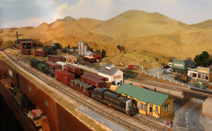
To most people, those hillsides of golden grass in the background do shout “California,” even before they know more about the locale, and that’s a good start.
     As I’ve said elsewhere, the entire idea of modeling an imaginary branch line of a familiar and well-known railroad was something I encountered the year I lived in England, and went to many weekend model railroad exhibitions. The typical exhibition layout, small enough to be readily portable, is an imaginary branch line of the Great Western, or London and North Eastern, or whichever railway was chosen. I liked the way this works, in that viewers readily understand the context of what they are seeing, and I have ended up doing it myself.
     There is a sense in which generalizing how things looked and worked in a particular area is more effort than simply modeling what was there in a particular place and time. Maybe not less modeling effort, but in some ways more research and analysis effort. But I enjoy those things, and for the goals I have, it works for me.
Tony Thompson

Wednesday, August 28, 2019

Modeling highway trucks, Part 8

The topic of this series of posts was chosen in part to emphasize my belief that anything a modeler can do, that emphasizes regional and local identity, is a big plus in the realism of a layout. We are sometimes urged to show evidence of national brands (for example, Shell Oil or Coca-Cola), and these brands are recognizable and thus helpful, but I think regional brands are better still. To see previous posts in the series, I would recommend using “modeling highway trucks” as a search term in the search box at right.
     A couple of my earlier posts were about longer semi-trailers, especially the very nice ones once made by Ulrich in all metal. As one example, the previous post, Part 7, was about these trailers (you can read that post at the following link: https://modelingthesp.blogspot.com/2019/08/modeling-highway-trucks-part-7.html ). But smaller trailers were also very prevalent in the 1950s, which I model, so this post is about them.
     Athearn for  many years made a 24-foot semi-trailer (these are still readily available via eBay and other on-line sellers), marred mostly by having dual axles at the rear, hardly needed on a small trailer. But in fact it is the work literally of seconds to use a razor saw to remove the forward axle in the dual-axle bogie, converting the trailer to something far more realistic (I first described this point on one of the earlier posts about highway truck modeling, which is here: https://modelingthesp.blogspot.com/2015/07/modeling-highway-trucks-part-3-more.html ).
     I recently picked up a few more of the old Athearn 24-footers for conversion. Shown below is one of the original Athearn paint schemes, for International Forwarding, at left, and at right is a trailer that has had the lettering stripped, repainted with Tamiya “Gloss Aluminum”(TS-17), and lettered with an appropriate truck graphic from Graphics on Demand (see their web site at: http://store.graphicsdemand.com/ ).
     The other trailer, at right, has not yet had its forward axle removed. I decided to letter that trailer for a very modern owner, Great Northern Brewing in Whitefish, Montana, which I only chose because I’ve visited there. But it’s out of era for my 1953 layout.


     Below are two more trailers re-lettered. I should mention again that the Graphics on Demand product is nicely printed on clear vinyl, and is a peel-and-stick sheet. With a coat of flat finish, it is all but undetectable on a model.  Here the companies are So-Cal Freight Lines and Coast Truck Lines. Awhile back, I did another trailer in the Coast lettering, but it was on the right side of a trailer, while this is a left side, giving me directional flexibility when showing this company on the layout.


     These are both regional companies. By the way, Southern California Freight Lines (its full name) has a long history, dating back  before 1950, but like many small companies from decades ago, it is hard to find much history on-line about most regional truckers. I recommend making the effort, but you may not find much in many cases.
      My final pair of trailer schemes also includes a left side of a scheme earlier done on a right side, for West Coast Fast Freight, and an elegant scheme for a company not done before, California Lines.


     All of these trailers are already in service on the layout, substituted for existing trailers to provide variety, which was the original purpose. I continue to seek out additional propsects for these kinds of trailer lettering, to extend further the variety I already have.
Tony Thompson

Sunday, August 25, 2019

Handling ice on ice decks, Part 4: modeling

In my first post on this topic, I described the ways that ice blocks were moved on icing decks, to bring them from storage to a position alongside a refrigerator car to be iced. On any but small ice decks, there was ordinarily an endless chain which was used to move ice along the deck. But in a very small deck, too small to justify the cost of a chain, a “runner” was used to guide the ice as workmen shoved or pulled it along with their ice tools. You can read that post at: https://modelingthesp.blogspot.com/2019/08/handling-ice-on-ice-decks.html .
     My own layout has a very small ice deck, barely over two cars, and I think this is relevant because most layouts only include quite small decks like mine. My layout’s ice deck is located at and owned by a company called Western Ice. As was common practice in small towns, Pacific Fruit Express has contracted with Western  to provide icing services.
     Western Ice only manufactures consumer ice (usually very slowly frozen so as to be clear), and the large ice blocks for reefers (more rapidly frozen and thus “cloudy” or white with innumerable trapped air bubbles) have to be brought in with ice service cars, operated by PFE. I described the ice used for reefers in a previous post (see it at: https://modelingthesp.blogspot.com/2019/08/handling-ice-part-2-ice-itself.html ).
     I have discussed modeling of ice service cars previously, along with some comments about the smaller ice facilities in Pacific Fruit Express territory. (That post can be found at: https://modelingthesp.blogspot.com/2013/07/more-on-ice-service-reefers.html .) Years ago, I decided to model Western Ice as a small ice storage building that would be appropriate to serve a minor branch line such as my Santa Rosalia Branch.
     Western’s ice house itself is simply a box built of styrene clapboard with corner trim boards. It only has one window that’s visible, next to the office door on the near wall (in the photo below), and has a raised consumer delivery door next to it. On the track side is another door, for unloading the shipped-in block ice for reefers.


     In the photo above, the ice deck is on the far side of the ice house. Below is a photo of this ice deck as built. It is just a set of timber bents, with a deck scratchbuilt from individual boards of pre-stained stripwood, then weathered. It has a stairway at the back. There is an ice door on the ice storage house, from which ice blocks can move out onto the deck. But there is no provision for moving ice along the deck.


The open hatches of the reefer standing at the deck can be closed when desired.
     The support for this deck is, as I said, a series of bents, grouped into “towers” in pairs, much like PFE did on many decks, as can be seen in the PFE book (Pacific Fruit Express, 2nd edition, Thompson, Church and Jones, 2nd edition, Signature Press, 2000).


     In the photo above, you will also notice the workmen on the deck, modeled so that one has a pickaroon and the other has a bi-dent, prototypes of which were shown in the first post of this series (see the link in the first paragraph of the present post). I showed awhile back my model figures with these tools (see the photos at: https://modelingthesp.blogspot.com/2017/05/figures-part-2-modifications.html ). Here is a view that includes the reefer.


     But as I said, the deck as originally built lacks any means of assisting ice movement along the deck. That’s the modeling project that I will describe in a later post, adding a “runner” on the deck that can serve as an ice guide.
Tony Thompson

Thursday, August 22, 2019

BAR reefers in PFE service, Part 2

In a previous post, I discussed the presence in Pacific Fruit Express territory of “foreign” refrigerator cars, that is, reefers not owned by PFE. I emphasized ordinary (AAR Class RS) ice-bunker cars used for produce loading, as opposed to, say, meat cars. You can read that post at: https://modelingthesp.blogspot.com/2019/08/foreign-reefers-in-pfe-territory.html .
     I spent some time in that post talking specifically about Bangor & Aroostook cars, because of a very interesting article in the BAR employee magazine, Maine Lines, about the lease of the entire BAR fleet to PFE between June 1 and October 1 of each year. Effectively every single BAR reefer went west for PFE use during those months, June through September, busy harvest season in PFE territory.
     What do we know about those BAR cars? First, we know that from at least as early as 1924, there had been a contract between BAR and New York Central’s Merchants Despatch (MDT) to provide empty reefers for use. That is documented in Roger Hinman’s book, Merchants Despatch (Signature Press, 2011). Such a contract obligated MDT to supply cars as requested by BAR, but had the drawback that when car supply was tight for MDT, they might not be able to meet all of the BAR requests.
     The first significant change in that situation was in 1950, when MDT was in the process of scrapping a number of older wood-sheathed reefers. These were cars built in the decade 1920–1930 and were being superseded in MDT service by steel reefers. As author Hinman put it, BAR bought cars “right off the scrap line” at MDT shops (page 159), and rebuilt them at their own Derby Shops.
     These cars went to BAR in the summer of 1950. The ORER (Official Railway Equipment Register) issue for July 1950 shows zero RS cars in the BAR listing, but in the following issue, October, there were 288 cars listed, and by the issue after that, January 1951, the full 325-car purchase was listed. Over the following years, BAR acquired a few more of these cars. For example, in the ORER issue for January 1953 (my benchmark for my own layout), there were 338 cars in this group.
     Some of these cars were painted in a striking scheme with a broad blue stripe across the lower part of the car and an upper white part, with a brown potato. This undated photo from the Bob’s Photo collection, shows the first car, numbered 6000 (all the BAR cars from MDT were numbered in the range 6000-6999).


This is one of the 1926-built MDT cars with corrugated steel ends.
     But we know that many of these newly acquired reefers were simply painted yellow (and a few years later, orange, instead of the dramatic blue-white scheme). Why the difference, and how many cars of each paint scheme were in the fleet, is unknown to me. I hope someone with BAR knowledge may volunteer information on that point.
     I chose to use a Red Caboose paint scheme of a BAR wood-sheathed reefer, which has the black railroad emblem as compared to the outline emblem you see in the photo above. I don’t know for sure which is correct for 1953 (or maybe both). I also suspect that the absence of lines above and below the reporting marks, and the absence of periods in the initials, may correspond to a time later than 1953.
 

     These rebuilt wood-sheathed cars were perhaps a stopgap for BAR, and during 1951, BAR went to Pacific Car & Foundry (the 1953 Car Builders’ Cyclopedia incorrectly says it was Pressed Steel Car Company) with an order for 500 new cars, very similar if not identical to the then-new PFE Class R-40-26, with sliding doors. These 500 cars were first listed in the ORER issue for April 1952. I have seen a wide range of dates assigned these cars in model publications, but clearly they were built at the beginning of 1952. Here is the builder photo included in the 1953 Cyclopedia (19th edition):


Before long, BAR went to Pacific Car & Foundry for 350 more cars, these placed in the 8000–8350 series, and those cars were dimensionally identical to the 7000-series cars.
     There is a fairly near car body to this sliding-door car, the Accurail 8500-series steel reefer (you can see their whole line at this link: http://www.accurail.com/accurail/ ). It is in fact a Fruit Growers Express prototype, and has a straight side sill instead of the tabbed sill you see above on the BAR car. The placard and route card boards seen above could easily be added to the Accurail model, as could some representation of the fan plate. I have in fact discussed these changes to make the very similar PFE Class R-40-26 car, in a previous post (and that post can be found here: https://modelingthesp.blogspot.com/2012/06/kitbashing-pfe-r-40-26.html ). Below is the Accurail model (Accurail photo).


Incidentally, this kit, Accurail 8511, appears to be currently in stock.
     I may eventually work on modifying one of the Accurail 8500-series models to represent a BAR steel car, but for now, the model shown above of a wood-sheathed ca, BAR 6166, r represents the BAR presence in the PFE fleet in harvest season on my layout.
Tony Thompson

Monday, August 19, 2019

Handling ice on ice decks, Part 3: icing

In the previous post, I described the kind of manufactured ice that Pacific Fruit Express used for icing refrigerator cars, an imposing 300-pound block that was a challenge to manipulate (you can read that post at this link: https://modelingthesp.blogspot.com/2019/08/handling-ice-part-2-ice-itself.html ). In the present post, I describe what was done with that ice block as it was put into the ice bunker.
     Both in published magazine photographs and in layout visits, I have noticed that some modelers evidently think that the 300-pound blocks were simply maneuvered into the ice hatch and dropped. This is not true, and you can understand two reasons why.
     First of all, at the beginning of icing, dropping a 300-pound block eight or more feet onto the steel grates at the bottom of the ice bunker would almost certainly do real damage. Second, filling an ice bunker with such big pieces of ice would be very inefficient cooling. The surface-to-volume ratio is pretty low. Instead, the ice should be broken up into much smaller pieces, thus far more surface area, for efficient cooling as air passes through the ice mass.
     What size were they broken into? The icing tariff identifies three sizes: chunk, coarse, and crushed. One of the PFE people I interviewed described these sizes as follows. Chunk ice was large pieces, not to exceed 75 pounds (a quarter block, since the ice block is 300 pounds). Coarse ice was about the size of a large watermelon. Crushed ice was not literally crushed by machine, at least not in hand icing, and was defined as about the size of a man’s fist. (Note that there is no category for 300-pound blocks.)
     The photo below is obviously posed, as neither man is actually engaged in moving anything, but it does show ice tools again, and the piece of ice is a quarter  block. The man on the car, called in PFE parlance the “chopper,” will chop this into smaller pieces if smaller ice is called for. The man on the deck using the pickaroon is called the “passer,” and the ice block is resting on an ice bridge. (This is a UP photo, image KE4-16, Richard Laurens collection.)


     The shipper chose the desired size to be iced, primarily on the basis of how rapid the car cooling needed to be at the outset. With an empty car that was not particularly hot, and a pre-cooled load, chunk ice might be specified. With a warm car or loads that weren’t completely pre-cooled, coarse ice could be chosen. And if there was a serious need for a fast cool, crushed ice would be specified, and still faster cooling could even be achieved by adding some salt, say 5 percent or 7 percent.
     Shippers often chose a coarser size for subsequent icing than for the initial icing, which was when the car got its first load of ice in the bunkers (icing the car before loading was called “pre-icing”). Usually salt would not be used after the initial icing when produce was shipped, and salt was uncommon in all produce shipping. Of course all these choices had an effect on the cost of “refrigeration service,” which would become part of the freight bill.
     I have not been able to locate a video on-line showing this kind of hand icing. I have seen such film, but can’t find one at the moment. But the chopper worked really fast, skillfully chopping and dividing the quarter-block that he was passed, almost as the block was falling into the bunker. Here are some photographs to illustrate what I am describing (the first three are PFE photos from CSRM). The first shows two passer-chopper pairs at work from an ice deck with lowered aprons. There is an ice bridge in use at the farther car, to move ice across to the far hatch. The block on the apron is a quarter block.


The second photo shows a chopper at work. He’s standing on the hatch plug, and an ice bridge is present at lower right. You can see he is chopping with his ice tool, right in the bunker opening.


     The third of these PFE photos was taken to show icing at night, and of course icing had to be done around the clock as needed. But of interest here, it shows the chopper just having sunk his bi-dent into the quarter-block to split it; pieces can then fall into the ice bunker. Note also that the passer has left some irregular chunks on the deck, probably when a block did not split cleanly.


     Last but not least, I want to show an example of icing other than PFE. Shown below is the Fruit Growers Express ice deck at Sanford, Florida. A PFE deck would have a roof, but FGE decks generally did not. Notice that the 300-pound blocks have been chopped a lot smaller on the deck, judging by the pieces on the ice bridge.


     These photo convey as much as still images can do. You will just have to imagine the dynamics.
     What does all this imply for modeling? First, the full-size blocks of ice coming onto a deck, whether with the aid of a continuous chain or not, would be the 300-pound size. Second, the blocks were split into quarter-blocks right next to a car being iced, so if any quarter-blocks are depicted at all, they would be right at the deck edge. Smaller pieces than that could result if a block split unevenly or broke into multiple pieces, so a few smaller chunks would be all right. But keep in mind that most of the sizing took place right at the car.
Tony Thompson

Friday, August 16, 2019

Handling ice, Part 2: the ice itself

In the previous post, I talked about how ice was handled when it had to be moved along the length of a wooden deck used for icing refrigerator cars (you can review that post here: https://modelingthesp.blogspot.com/2019/08/handling-ice-on-ice-decks.html ). In the present post, I want to say a few words about the ice itself.
     One of the largest ice consumers in the world in the early 1950s was Pacific Fruit Express, using about two and a half million tons of ice in 1952. A summary of the PFE approaches to ice (both natural and manufactured) can be found in the PFE book (Pacific Fruit Express, 2nd edition, by Thompson, Church and Jones, Signature Press, 2000). Here I want to just show a few illustrations.
     Since the 1920s, the standard PFE manufactured ice block weighed 300 pounds. It was a truly imposing object to handle. Often in PFE ice houses and on ice decks, a sign could be seen, that read "That block of ice is bigger and tougher than you are. Watch it. Safety first.”
     These ice blocks were made in rectangular steel containers called “cans.” The cans were handled with a system of overhead hoists. The first step was to fill the cans with city water, as seen in the photo below in the Roseville ice plant in 1924 (this was the largest artificial ice plant in the world). Six full cans weighed almost a ton.


(These first three black-and-white images are PFE photos, from the author’s collection, now in the California State Railroad Museum.)
     The filled cans were moved to an opening in the ice plant floor, where they were lowered into a circulating brine solution, cooled below 20 deg. F. All this planking is removable.


     When a group of cans had fully frozen, they were lifted out of the brine and taken to a station where they could be hosed with warm water to loosen the ice, then the ice blocks could slide out.


     It’s important to recognize that the ice was frozen as quickly as possible. This means that dissolved air in the original water fill would be rejected by the freezing ice in the form of bubbles, but during rapid freezing, these bubbles could not escape and remained trapped in the ice, making it opaque. If freezing is done sufficiently slowly, these bubbles can escape and leave the ice clear, as is usually desirable for consumer ice.
     Here is a photo of ice arriving on the ice deck in Roseville. It is obvious that the ice is quite white in appearance. This is what one sees in reefer icing photos from anywhere in North America. The burlap covers, incidentally, are to reduce ice block wastage (by melting) before they are needed.


      I mention this because some modelers have used clear plastic blocks to represent ice (several commercial kit makers have offered such ice, including Campbell and some others). But of course this is entirely non-prototypical. Note also that the ice blocks shown above do not have sharp edges and corners, but have become rounded with handling and wastage.
     My view is that the least one can do with clear plastic ice blocks is to sand them to make the surfaces cloudy, and round all edges and corners. This is still a translucent ice block rather than white, but to many viewers it “reads right” as ice, where a dead white block might not.


Note that these figures have the two ice tools I described in the previous post (see first paragraph for link), the bi-dent at left, and the pickaroon. I will say more in a future post about my model ice deck.
     I will return to modeling in reporting on changes to the ice deck in my layout town of Shumala in subsequent posts.
Tony Thompson

Tuesday, August 13, 2019

Modeling highway trucks, Part 7

I have written a number of posts on this topic precisely because I think this is a part of layout modeling that is often neglected. One of the ways we can portray a region and a period is through use of correct graphics on highway trucks, and by correct, I mean the regional and period details of truck companies and truck lettering. I have shown a number of examples in previous posts, all of which on this topic are readily found by using “highway trucks” as a search term in the search box at right.
     For the present post, I was chasing information on the Denver-Chicago Trucking semi-trailer that I showed in my post that described correcting the roof which a previous owner had unaccountably painted blue (that project turned out well, as I showed: https://modelingthesp.blogspot.com/2019/07/modeling-highway-trucks-part-5.html ).
     Knowing that in more recent years there was a firm called Time-DC, and that the DC stood for Denver-Chicago, I looked into the history. I soon found that the very large trucking firm, Time-DC, was formed in 1969 in a merger of Time Freight, Denver-Chicago Trucking, and Los Angeles-Seattle Motor Express. I have already shown some semi-trailers lettered for the latter company (see that post at: https://modelingthesp.blogspot.com/2015/07/modeling-highway-trucks-part-3-more.html ).  I repeat below one of my earlier images, since those posts were back in 2015.


Obviously in my modeling year of 1953, long before 1969, all three companies, Time, D-C, and LASME, were independent and operating under their own names. Moreover, both Time and D-C became full nationwide carriers in the 1950s.
     Once again, I turned to a great source for truck graphics, Graphics on Demand (you can visit them at: http://store.graphicsdemand.com/ ). They have a truly staggering array of trucking companies covered, but beware: all eras are intermixed. You have to spend a little time with your good friend Google to check on the various companies and when they were in business, and in many cases you also have to search out photos to determine which lettering schemes go with which period.
     I will say, in passing, that there are plenty of 1950s schemes in their selection, even though the majority of the products are for distinctly more recent companies. My impression is that modelers of any era after World War II will find truck lettering that they can use. But it is very definitely a case of caveat emptor.
     I used their Time Freight truck graphic on an Ulrich semi-trailer (these are usually available on eBay and comparable sites, though prices vary; worth watching sales for a bit before plunging <grin> but that’s your call). I applied the Graphics on Demand graphic, which is not a decal, but a shiny vinyl “peel and stick” product with a clear background, easy to work with, and completely made invisible with a coat of flat finish. Here is the result (you can click on the image to enlarge it if you like):


The truck is shown on Pismo Dunes Road on my layout, passing a Bekins Van Lines semi-trailer going in the opposite direction (also made with Graphics on Demand lettering).
     I also wanted to add a semi-trailer for Associated Transport. Though originally formed by several trucking companies in the east in 1942, with routes from Florida to New England and as far west as Cleveland, it soon served a far wider territory. I can remember seeing Associated trailers in Southern California as a boy in the 1950s. Their lettering scheme was quite simple, and here is the model, using the Graphics on Demand lettering.


This is an ancient Tyco trailer that I like because it is rib-sided, as were many AT trailers. It’s shown on Bromela Road in my layout town of Ballard, looking past the Guadalupe Fruit Company building at left.
     I repeat my comment, that I believe highway trucks offer us another modeling tool to depict the region and era represented by our layouts. I will continue to research possible additions to my own semi-trailer fleet in the near future.
Tony Thompson

Saturday, August 10, 2019

Handling ice on ice decks

In the earliest days of refrigerator car icing, decks for icing or re-icing of cars were simply wood, as in the photo below. If a deck like this were not pretty wet, moving ice along it was not easy. This interesting 1915 photo of icing was taken at Portola, California on the Western Pacific. Ice has been delivered from the box cars at right, on an elevated track, and is being placed in the refrigerator cars at left. Deck is all wood, but the ice only has to be moved across the deck in this situation (Whitehead photo, Richard Laurens collection).


This photo is included in the PFE book (Pacific Fruit Express, 2nd edition, Thompson, Church and Jones, Signature Press, 2000). The deck was owned and operated by PFE.
     Before many years, it was realized that adding a “runner,” often a channel to keep the ice moving in a straight line, was an improvement. Early ones were sometimes wood, but a strip of sheet steel was better. The photo below, a detail of an image from the American Refrigerator Transit book (by Maher, Michels, and Semon, Signature Press, 2017) shows the ice deck at Grand Junction, Colorado, probably not long after 1920. The channel for ice blocks can be seen approximately in the deck center (photo from the History Colorado collection, courtesy Gene Semon).


     On a deck serving substantial numbers of cars, however, the ice volume to be moved was so large that mechanization was essential. Almost always, the solution was an endless chain, with projecting “dogs” at intervals to move the ice blocks. The photo below, also a detail from one in the ART book, shows the chain on the Harlingen, Texas deck in the 1930s (Central Power & Light photo, courtesy Gene Semon)


There are lots of photos of big ice decks with ice blocks being moved with chains. Here’s an example, an excellent Don Sims photo of icing at Yuma. Ice blocks on the chain can be seen at far left.


     A quick word about ice tools. There were two “standard” tools used throughout the U.S., one for moving ice (that was called a “pickaroon” by PFE people), and an ice-chopping tool called a “fork” or a “bi-dent,” the latter I guess by analogy with a trident. Both are shown below in one of the greatest of all icing photos, taken by Jim Morley at Roseville in 1948. The “passer” on the deck is moving an ice block to the “chopper,” who will chop it to smaller chunks as it reaches him and starts to fall into the bunker.


The pickaroon has a wooden handle and obviously could be used to either push or pull ice blocks. The bi-dent is forged steel and a very heavy tool. The photo preceding this one shows the same tools in use.
     In the early 1950s, the locations that iced lots of cars began to add mechanical icing, using machines that ran along the deck on rails and could take ice off the chain and break it up to the desired size as it was being dumped into ice bunkers. This was in fact no faster than manual labor, but only required one or two workers, instead of 8 to 15 workers doing hand labor. But smaller places continued to ice cars by hand.
     Like other companies responsible for providing ice for refrigerator cars, PFE built and owned its largest plants, which manufactured ice. But in smaller towns, they would contract with a local ice company to provide ice.
     In some cases, PFE would build, own and maintain the ice deck, even though the local ice company supplied the ice and the labor for icing. Such a PFE deck was almost always located at the local company’s ice plant. In other cases, the local ice company would build and own the deck itself, thus providing all services. Many examples of all these arrangements are documented in Chapter 13 of the PFE book.
     Small decks, that could not justify the expense of adding a chain, let alone icing machines, were most easily worked with a “runner,” as shown above, a channel or strip of steel sheet that made it easier to move ice along an icing deck. This is especially pertinent for models. The ice deck on my layout is pretty small (as indeed are nearly all model ice decks), and a runner seems the most that could have been included on it.
     I will address modeling such a runner for my layout’s ice deck in a future post.
Tony Thompson

Wednesday, August 7, 2019

Railroad shipping related to beer, Part 2

I introduced this topic with a post about the kinds of railroad shipping associated with the making of beer (not the shipping of the finished product), emphasizing malt and hops. That post can be found at this link: https://modelingthesp.blogspot.com/2019/07/beer-as-industrial-commodity.html .
     In that post, I mentioned that malt, after its use to provide the liquid that is fermented (called “wort”), can be used for other purposes, and is then usually called spent grain. These include animal feed (well regarded as chicken, pig, sheep and cattle feed), as fertilizer, and as fuel. Fuel, you say? Yes, when dried it can be burned to provide heat for the brewing process, and some breweries do that; but in that situation it isn’t shipped. If you’re interested in this topic, here’s more: https://www.craftbeer.com/craft-beer-muses/sustainable-uses-of-spent-grain .
     I should emphasize that this is not a small matter. For each gallon of beer produced, about 10 pounds of spent grain are left over. Being able to market this material can contribute significantly to the revenue stream of a large  brewer. Even home brewers may wish to make constructive use of the spent grain.
     Spent grain is shipped in bulk for both fertilizer and feed, and is shipped in bags for feed. Accordingly, I have used box cars for the bagged product, and covered hoppers for bulk shipment, on my layout. Obviously any box car could carry bagged feed, but an interesting example might be a car from Manufacturers Railway Company (MRS), a captive rail service in St. Louis for brewer Anheuser-Busch. The MRS once operated a number of Mather box cars, and an MRS model in HO scale was produced by what was then the LifeLike Proto2000 line.
     One of these model cars is shown here spotted at the small freight shed in my layout town of Shumala (this shed was described in an article in Model Railroad Hobbyist, in the issue for August 2018; this issue can be read on-line or downloaded, for free, at the MRH website, www.mrhmag.com ).


Shipping spent grain from the brewer in its own box car is a nice touch, though I am sure that all or nearly all of Anheuser-Busch’s spent grain was sold much more locally. But let me repeat that any free-running box car might have been loaded with a cargo like this.
     Bulk shipping of spent grain for feed purposes might well be directed to a team track, where a consignee could unload the cargo with the help of equipment such as a mobile auger unloader (to see an example of such, consult this post: https://modelingthesp.blogspot.com/2017/11/unloading-covered-hoppers.html ) or other device. An example waybill might be something like this, directing the load to the team track in my layout town of Shumala:


The Blitz-Weinhard Brewery in Portland was switched by the Northern Pacific Terminal, a switching road, which, like many terminal railroads, had all its paperwork produced by principal owner NP, as you see here.
     Shown below is the car referenced in the waybill above. This is an InterMountain covered hopper, re-lettered with Champ decals and numbered for a series of Shippers Car Line cars with the same 1958 cubic feet capacity as the model. It also has reweigh and repack stencils, and the air reservoir stencil.


This car, of course, could find itself assigned to carry a variety of cargoes, as it is not lettered for any lessee or company-owned product.
     I continue to examine other opportunities for railroad shipments of beer-related products that can plausibly move on my layout. This is part of the interest in operations for me.
Tony Thompson

Sunday, August 4, 2019

My article in the new MRH

In the August issue of Model Railroad Hobbyist or MRH, my contribution to the “Getting Real” column series is an article about building a “see-through” industry, which means an industry you can see through onto the layout. In my case, it is located right at the aisle edge in my layout town of Ballard, and by implication is only the outer wall of a large structure, imagined to lie in the aisle.
     (MRH remains on line, at www.mrhmag.com , but my column is now in their recently introduced  supplement section called “Running Extra,” which takes a subscription to view — costing $2.99 for the single August issue, or with an annual subscription the cost is $1.67 a month — so I can’t offer you access to it without payment.)
     I have seen this kind of layout-edge industry representation called a “fascia flat,” meaning that it is located at the fascia edge of the layout, but since mine can be seen through, I decided that the name “see-through industry” was more descriptive. The biggest advantage, of course, is that it takes up so little space, but there is a visual interest in being able to look through the doors or windows of such an industry.
     I decided to make this structure have an open-framed interior wall, which of course is the wall we see from the layout aisle, and that in turn meant I needed to understand how prototype frame buildings are actually framed. For that, I turned to a truly superb book on the prototype, by noted architect Francis Ching. Shown below is the cover of the current 5th edition. You can readily find this title for sale on line, as a new book or, if you prefer, from used book sellers, either the 5th edition or one of the earlier editions.


This book is, to a lay person, remarkably complete and detailed, though to an experienced architect or carpenter is probably mostly old news.
     I used styrene sheet and strip to build the building, as described in some detail in the MRH article, and though it was tedious at times, it ended up looking like I had hoped it would. Shown below is an in-progress photo from the article. Here you can see that all the wall studs and the top plate are installed, and I am in the process of installing floor joists. You can just see the underside of the roof at top left, and clearly rafters remain to be added.


     Completion of the building included interior detailing of the part you can see, with a variety of tools, signs and placards, furniture, and workmen (you can click on the image to enlarge it if you like). Its name, Western Packing Company, is on the fascia, beneath a protective sheet of clear acrylic plastic. In this photo, what you see below the building is part of my layout staging.


     But the payoff in many ways is the minimal footprint of this structure on the layout. The photo below, showing a viewing angle not available at the layout without getting onto a stool and leaning way in, is not one that visitors can experience, but it does show the result. On the building wall is the business name, which I felt like I had to add, even though it can’t be seen. As is evident here, three reefers can be loaded at once at this packing house; the loading dock is barely visible.


     This was a fun project to research and even to build (glossing over the tedious bits), and I am pretty pleased with the final result.
Tony Thompson

Thursday, August 1, 2019

Foreign reefers in PFE territory

Those interested in refrigerator car operations in the 1950s will know that most owners of such cars borrowed cars from other owners from time to time. Sometimes these were formal leases, sometimes they were other kinds of agreements, such as simple one-time loans.  The point of these agreements was two-fold: first, of course, for the borrowing or lessee operator to have enough cars to serve their shippers; but second, putting the cars to work generated revenue tor the lessor or loaner from otherwise idle cars.
     Pacific Fruit Express was certainly no exception. Though their fleet of about 40,000 cars was the largest in North America by 1950, they nevertheless did not have enough cars to cover peak harvest periods in the August to October time frame. In the early 1950s, PFE’s own statistics show that about a quarter of all carloads moved by PFE in peak season were in foreign cars, that is, cars not owned by PFE.
     Some of the “foreigns” were informal car loans, ad hoc arrangements with car owners in particular seasons, but most were either leases or car-use contracts. In a lease, an agreed number of cars was turned over to the lessee for the period of the lease, and operated as the lessee wished. In a contract, normally cars were supplied according to demand, rather than a block of cars all being turned over to the receiving user.
     We know from employee recollections, conductor log books, and from photographs that the biggest source of PFE foreigns was American Refrigerator Transit (ART). I have discussed this in prior posts (for example: https://modelingthesp.blogspot.com/2011/08/modeling-freight-traffic-coast-line.html ). As far as I can determine, this was a contractual arrangement. Here’s an example (you can click to enlarge):


This photo, taken by Al Phelps near Antelope, California on September 10, 1950, shows SP Mikado no. 3306, with a 99-car train of all reefers, plus caboose, headed eastward and about to reach Roseville. The first three cars happen to be ART cars, though no other ART cars are recognizable in this train.
     Two other major sources of foreign reefers in PFE territory were Merchants Despatch (MDT) and Fruit Growers Experess (FGEX, along with pooled operation of BREX and WFEX cars). Again, photos show these kinds of cars in trains and in yards, but important data from a conductor’s records provide statistics on these cars’ presence (see my analysis in this post: http://modelingthesp.blogspot.com/2011/02/modeling-freight-traffic-coast-line.html ). 
     Another well-known source was the Bangor & Aroostook Railroad (BAR). The BAR fleet was primarily intended to serve their own shippers of potatoes, which was a traffic peaking in the late fall and continuing through the winter. This was nicely matched to PFE, whose traffic was tapering off by then, and who would be happy to return the BAR cars in late fall. In this case, the car transfer was under a lease. The actual dates of the PFE lease were from June 1 to October 1 of each year.
     I want to thank Ed Shoben, who contacted me with questions about the relation between PFE and BAR, and who sent me an interesting 1957 article from the BAR employee magazine, Maine Lines. I understand that the article was provided to Ed by Ron High. I have used the scans sent to me to create a document on Google Drive, which anyone can access at the following link:

https://drive.google.com/open?id=1oMSf7nqfDl5oCcyrAJZUOlf-m94oexjp

This is a fascinating description of how the lease of the BAR cars to PFE looked from BAR’s perspective.     
     The article also mentions Merchants Despatch as a source of refrigerator cars for BAR. Those MDT cars were available as part of a long-running contract (since 1924), not a lease, and car availability was not always what BAR wanted, thus the ownership of a large fleet of their own cars.
     Careful study of train views in the West will show an occasional BAR reefer in among the PFE and other reefers in a train. The example below is another Al Phelps photo, this one taken at Broderick, California (now part of West Sacramento) on September 3, 1955, with cab-forward SP 4179 powering a fruit block from San Jose. The BAR car nearest the camera is no. 7107.


Another example, an SP photo, shows a BAR car in a freight train in a siding west of Truckee, meeting passenger no. 27, in March, 1952.


     These photos both happen to show the new BAR sliding-door steel reefers, built by Pacific Car & Foundry as copies or near-copies of the PFE Class R-40-26. But BAR also had a number of wood-sheathed reefers.
     (I should reiterate, as I’ve said several times in the past, that Santa Fe was emphatically not among the sources of foreign reefers for loading in PFE territory, and the same was true for PFE cars in Santa Fe territory. Cars of both fleets were returned empty to their owners, as employees of both companies have said, because neither wished to load its competitor’s cars in its territory.)
     But let me return to BAR. For a modeler of PFE territory, as I am, including BAR reefers in one’s freight car fleet is both interrsting and prototypical. I will return to the BAR car fleet, and to modeling issues, in a future post.
Tony Thompson