Wednesday, April 28, 2021

Car fleet management

 I have often posted commentary about my fleet of freight cars, including detailed descriptions of how cars have been chosen for the fleet. I have also talked about the general problem of keeping track of a car fleet (for example, in this post: https://modelingthesp.blogspot.com/2013/10/evaluating-freight-car-fleet.html ) and managing its use. On my layout, this applied to scenes such as this one, with all kinds of freight cars clogging up Shumala. What is going on here? That is my topic today.

The scene above represents the transition from one operating session to another. So the sub-topic is, if you will, how is this process managed? I first began “fleet management” in the simple hope to have a rational basis for the cars operated in the fleet, for example the well-known Gilbert-Nelson idea, that freight cars everywhere essentially are present in proportion to their owning railroad’s proportion of the national car fleet (for background on this idea, you can use “Gilbert-Nelson” as the search term in the search box at right).  

But I actually began record-keeping on the car fleet during the time my layout and its rolling stock were in storage, and not readily accessible. I found that hobby shop and train show visits were resulting in purchases that duplicated kits or built-up cars I already had. 

So I laboriously made up a complete inventory list of all the kits that I had. I also listed where the kit was physically stored, so I could find it when needed. Then when I went places that cars might be purchased, I would print out the inventory pages to take with me. Duplication basically stopped.

Many of the kits in that initial inventory are built or gone, but I still maintain a list of what remains. Even today, it looks like this, with location in the column at far right (these are a few sample lines; you can click to enlarge):

Gradually, as various of these kits were assembled and put into service, I simply moved the entry for that kit to a separate section of the inventory, called “In Service,” and entered the date of completion of the car. Again, I tried to write enough information to fully identify the item. This section looks like the brief sample below.

And when I disposed of a kit, by sale or gift or however, I moved that entry to yet another section, for items removed from the list. It’s usually entitled something like “Gone.”

Now I realize this is quite a lot of records for a big car fleet, and indeed it was a fair amount of work when the original inventory was created, more than 15 years ago. But the various kit completions or disposals happen gradually over time, so that it only takes seconds to update a new acquisition or disposal, or placing a car in service. 

I don’t describe this system because I think anyone should copy it, and certainly not because I think it’s a great system. But it’s a system. I do think some kind of record keeping like this can be of benefit to many modelers.

In addition to the foregoing, when a particular car has entered the “In Service” category, I also place a copy of its entry into my “Master Roster”  of the entire fleet. I have described my Master Roster previously, as part of a description of how I set up the layout for an operating session (see this post: https://modelingthesp.blogspot.com/2017/07/waybills-part-59-more-on-op-session-set.html ). 

To illustrate its contents, here’s a few lines from the current Master Roster, to serve as examples. Note that I have the storage location noted (third column) and the dates of operating sessions when the car had been used.

Again, this is quite quick to update, after an operating session. Then the next step before the next session is to pull off the cars that have completed work (delivered a load and returning empty, or set out empty, and now returning loaded), and begin to add the cars needed in the  next session. (That’s the process that is underway in the top photo in this post.) 

I thereby not only make sure that we don’t see the same cars, session after session, but also make use of as much of the whole fleet as I can. Whether this would appeal to other modelers, I have no idea, but it works for me.

Tony Thompson

Sunday, April 25, 2021

Modeling SP passenger cars, Part 10: trucks

 A number of my model sleepers, both heavyweight and lightweight, are stock or modified AHM (Associated Hobby Manufacturers) plastic cars, manufactured by Rivarossi. In the latter part of the 20th century, these were ubiquitous in hobby shops and swap meets, and can be modified beyond their original form. 

Earlier parts of my series of blog posts on SP passenger cars showed my conversions of some of the heavyweight Pullman  cars to various different floor plans (the easiest way to find all of the series is to use “modeling SP passenger” as the search term in the search box at right).

An important part of these conversions is couplers. Although I body-mount couplers on shorter cars, on 80-foot cars there can be problems on curves sharper than about 36 inch radius. My solution has been to modify the original AHM Talgo-like arrangement. I mentioned this briefly in one prior post (see it at this link: https://modelingthesp.blogspot.com/2014/09/modeling-sp-passenger-cars-sleepers.html ), but want to expand on that description here.

The photo below shows the sequence. At left is the truck as produced by AHM, with a long, spring-loaded tongue, terminating in a molded-in-place horn-hook coupler.  I simply cut off the horn-hook coupler, then drill and tap the tongue for a 2-56 screw, as shown at center. Then a regular Kadee coupler box is attached on top of the tongue, using a screw, right. I continue to use Kadee #5 couplers on passenger cars because of their wider gathering range, though nearly all of the rest of my rolling stock is being converted to Kadee #58 couplers.

The trucks shown above happen to be 4-wheel trucks, but of course the exact same process is used with 6-wheel trucks. Shown below is one truck of each type, drilled and tapped. The length of the tongues appears different at first glance, but in fact, the distance from bolster center to the drilled hole is the same for both trucks.

An advantage of this kind of mounting for couplers is that they are then located just about ideally at the car end. Shown below is a car end without diaphragms, so the coupler can be clearly seen.  The car here is a Lark sleeper.

Another issue with the Rivarossi design is that trucks are attached with friction pins. This works all right when the models are new, but after a few truck removals and replacements, for painting, maintenance or whatever, the pins are no longer doing their job very well. The simple solution that I’ve used is to drill out the body bolster hole with a No. 30 drill, insert 1/8-inch Evergreen styrene tubing and glue with Plastruct “Plastic Weld,” and then tap the inside of the tube for a 2-56 screw. Then it looks like this:

I have several of these 10-6 sleepers, reasonable stand-ins for Southern Pacific’s post-war Pullman-Standard sleepers, assigned to several trains, including the Coasdt Route’s Lark. I will say more about the paint and lettering, and my layout uses of the cars, in a future post. 

Tony Thompson

Thursday, April 22, 2021

Tony Koester’s new book on layouts

 Kalmbach Media has released a new book by Tony Koester (many will realize this is an approximately annual event), this one packed with interesting and useful insights about layouts. The cover is shown below. You can purchase it at many hobby shops, and I certainly advocate supporting your own local shop, but purchasing it direct from Kalmbach makes more money for them (that’s what I did). Notice I don’t mention on-line sellers like Amazon, who take quite a slice of the revenue. Your call, of course.

The book is the standard Kalmbach soft-bound format, 112 pages, 8.5 x 11-inch size, priced at their usual $21.99. Sadly, it was manufactured in China, even though there are superb and competitive printers in the American Midwest. As usual, photographs are beautifully reproduced throughout. Numerous images depict Tony’s own Nickel Plate and Allegheny Midland layouts, so will be familiar scenery to many.

The book started out as an effort to comb through and compile some of the more interesting columns that Tony has written in his ongoing “Trains of Thought” series in Model Railroader, now approaching 35 years worth (!). 

But as Tony notes in his Introduction, he soon went beyond that, and took several of the themes he recognizes in the columns, and made a chapter out of each. Below is the Contents page; you can click on the image to enlarge it if you like. 

You can see the themes clearly in the Chapter titles. Nearly all do relate to layouts as such, but go farther, to what a layout represents, and how it can have both more realistic looks and operation.

As always, the author writes clear and interesting text, and has chosen excellent illustrations, if perhaps a few too many of the most familiar layouts. The points are made repeatedly, that modelers can and should learn from the prototype, and adapt what they learn to recreate those lessons in model form. This is an ongoing theme from Koester, but one which certainly bears emphasis once again.

I really enjoyed both browsing and close reading of this book. The layout of the book allows for generous sizes of most photos, and often of equal importance, without too much cropping of the model scenes. I reproduce below just one example of a double-page spread, in an effort to convey how attractive a book it is.

As with any book by Tony Koester, this one is not just informative and educational, but is pleasant and interesting to read. Almost any of us will learn or re-learn a few lessons, and if you have, or are building, a layout, you will recognize how practical and sensible the commentary is. I recommend it highly.

Tony Thompson

Monday, April 19, 2021

Open-car loads: A full load of ties

 A common load in gondolas in any era would be railroad ties. Particularly in the wood-tie era, tie replacement was necessarily a continuous process, and might be going on anywhere, any time, on the railroad, and ties needed to be taken to those areas. A couple of years ago, I wrote a blog post about tie loads, which is at this link: https://modelingthesp.blogspot.com/2019/02/open-car-loads-ties-in-gondolas.html . The load I built, that was shown in that post, was a partial load, suggesting that ties were delivered to at least two locations.

(Incidentally, I have written an entire series of post about open-car loads, for both flat cars and gondolas, and you can most easily find them by using “open car loads” as the search term in the search box at right.)

The diagram I showed for ties in gondolas, taken from the 1926 ARA Loading Rules book, was shown in the previous post cited in the top paragraph, above; for simplicity, I repeat it below.

Now a model load of the kind shown in the above diagram could be assembled in a gondola with all loose ties, just like the prototype. But even the lightest bump of the model gondola can disarray the ties. You can doubtless guess how I know this. So at least some of them need to be glued.

For the present post, I set out to build a full load. The first step was the stack of ties, shown in black at the left in the above diagram, which is “6 x 6” (six ties wide and six ties high). I assembled this stack with canopy glue, using some Model Hobbies ties I had on hand. I also assembled a couple of rows of ties, nine ties wide, with canopy glue. You could of course keep on making rows like this until you fill the car.

But if you do it that way, you not only have a whole bunch of gluing to do, you also permanently consume ties. It struck me that there is an alternative: I tried just taping a couple of rows with Scotch tape. The tape, of course, would be hidden between the row of ties inside the car, and the ties would be easily recoverable by removing the tape.

Placing the tie rows, and the end pile, in a car body reveals that although HO scale gondolas vary in width, even the more narrow ones do accept the standard 9-foot tie. Here is the beginning of stacking these “sheets” of ties in a gondola. One feature I like about the taped sheets is that if one looks a little too irregular, or not irregular enough, just peel off the tape, re-position, and re-tape.

Although your stack of the sheets of ties may not come out exactly to reach perfectly to the end of the car interior, you can lightly jiggle the tie sheets and get the last row to sit right at the car end.

A load of ties like this, or even a half-load, as I have previously described, makes an interesting car in a mainline train, and of course can be waybilled to any layout location where a track foreman might get a fresh stock of ties. This could be almost any siding or spur, or if you have one, a work area or outfit track. Mine are already in use.

Tony Thompson

Friday, April 16, 2021

Mobil Oil in California

 Many readers will know that the Mobil Oil Company, as it was later known, was an outgrowth of the breakup of Standard Oil in 1911. The oil products parts of Standard became regional oil companies (sometimes called “Baby Standards”) and various other parts of the huge company also became independent entities. One of the Baby Standards was Standard Oil Company of New York, with the acronym Socony. As the name says, this was an eastern United States regional company.

But with time the various regional companies began to pursue their own interests as needed, often overlapping into each others’ territory. They also absorbed other oil companies over the years. Socony was no exception. In 1931, they merged with the Vacuum Oil Company (so named for a refining technology) to form Socony-Vacuum. 

Socony had been marketing gasoline and petroleum products under the name “Mobil” since 1920, and continued after the merger.  In fact, the company was to be re-named “Socony-Mobil Oil Company” in 1955, but that’s after my 1953 modeling date. The use of the “flying red horse” as a trademark, begun in the 1920s, continued for many years. 

But how does California come into this? Wasn’t Socony, as its name implies, an Eastern company? In fact, Socony, in various guises, operated in many parts of the United States, including a refinery at Torrance California, near Los Angeles. Built by Vacuum Oil in 1907 and operated by them until the merger with Socony, the refinery continued under Socony-Mobil, under Mobil Oil Corp. when that name change occurred in 1966, and then by Exxon when it merged with Mobil in the 1990s, and still operates today, though no longer under the Exxon name.

(Incidentally, as I have pointed out in previous blog posts, the history of all California oil refineries is conveniently available, in a fine web page at: https://www.energy.ca.gov/data-reports/energy-almanac/californias-petroleum-market/californias-oil-refineries/california-oil .  Comparable refinery histories are available on-line for other regions of the U.S. and for particular states.)

At one time, the tank cars of Socony-Vacuum were assigned to particular divisions. In 1940, for example, the White Eagle Oil Division (a predecessor) had the WEOX mark, while the White Star Refining-Ohio Division cars were marked WSRX. By 1946, those older marks were discontinued, and cars were listed as “Eastern Region, Socony” and carried the reporting mark SVOX. By the 1950s, cars were listed under “Central Region,” headquartered in Kansas City, and with reporting marks SVX.  Cars of course were operated throughout the country as needed. 

Given the refinery and the many Mobil gas stations in Southern California, I can certainly operate Socony-Vacuum tank cars on my layout, and indeed I have two.  One of them models the famous all-red scheme with the large “Mobilgas” lettering. Here is a prototype photo, taken in Los Angeles in the late 1950s (after the reporting mark change to SMX for Socony-Mobil), from the Bruce Petty collection. You have to love the spillage below the dome!

This scheme has been possible in HO scale for some time, both in factory paint and in decal form. Here is the model I have, inherited from Richard Hendrickson’s fleet. Note that it is a brighter red, not the faded-to-orange of the prototype photo above.

I also have a second Mobil tank car, this one in an earlier “Mobilgas” scheme, and it is a brass car from Precision Scale. It does have a problem, in that the reporting marks applied by the factory are SOVX, a reporting mark that never existed, as far as I can determine. (You can click on the image to enlarge it, if you wish.)

There was at one time a SVOX mark, for Socony-Vacuum Oil, but not SOVX. Moreover, the SVOX mark was replaced before 1950 by SVX. The solution, then, was simple: a paint patch to shorten the reporting marks.

This Precision Scale car is interesting in that it is an insulated and jacketed car, and has the kind of dome-top fixtures used for some chemical commodities. Although I don’t know the full range of products that were made at the Torrance refinery, several simple chemicals are certainly possible, and I will likely make waybills for this car accordingly.

Mobil petroleum products, and the “flying red horse” logo on service stations, were very familiar on the West Coast in the 1950s, my modeling era, so I am happy to operate both these cars on my layout.

Tony Thompson

Tuesday, April 13, 2021

Redetailing a C&BT Shops box car

 In the late 1980s, a new manufacturer of HO scale freight cars emerged onto the scene, called C&BT Shops. The models were produced from all-new tooling, and many of the car bodies were very well done. 

However, as I know from having lived in Pittsburgh at the time, and being acquainted with Dick Schweiger, the proprietor of C&BT Shops, there was a problem: molds for the detail parts sprues hadn’t been made before the original toolmaker passed away. The unfortunate result was good car bodies but very poor detail parts, created by a replacement toolmaker of distinctly less skill. 

It occurs to me that there must be modelers today who have never seen a C&BT kit. I show below one of the original kit boxes, which also serves to illustrate the era when C&BT Shops came onto the scene. The maroon and gray colors were very fashionable in the early 1990s, and the elegant “look” of the box was a considerable contrast to the ubiquitous kit boxes of the day from Athearn or Model Die Casting.

At one point early in C&BT’s existence, Dick Schweiger gave me some discarded car bodies, surplus because they had been used to try out some variations in pad printing of lettering. Dick gave them to me rather than throwing them away, because I said I could use them as fodder for kit conversions. The body I am working on at the moment had smeared lettering on one side.

The core idea of any project to “rescue” these good C&BT car bodies, in essence, is to firmly propel all the kit detail parts into the wastebasket, and replace them with a variety of superior detail parts available today. In my case, I didn’t even have to discard any parts, because all I had was the donated car body. But I did make the same kind of fresh start, adding all new detail parts.

My first step was to fill all the attachment holes, intended for ladders and grab irons, with modeling putty (I use Tamiya gray). Then I added wire grab irons from Westerfield, and decent-looking ladders from my parts box (not sure of the origin). Here is the car, on “interim truck support blocks,” with its overly-heavy New York Central lettering, which I won’t retain.

Next came sill steps, and brake gear on the B end of the car. I used A-Line “Style A” sill steps, and some AB handbrake parts from the parts box. With all side and end details complete, I added a representation of a metal grid running board from Kadee, part 2001, attached with canopy glue, and was then ready for paint. 

First, I lightly primed sides and ends with Tamiya Fine Surface Primer, a nearly white color, to neutralize the existing lettering. It’s not necessary to make the color entirely uniform, only to lessen the contrast between body color and lettering.

Then I chose the Oxide Red color of Tamiya Fine Surface Primer as a body color. This paint has good covering power, so can easily color the entire car uniformly. It also has a light gloss, suitably for many decals.

This completes the modelling work on this project. I think it is evident on this car body what superior detail and proportions it has, things that are easier to see when the original kit’s clunky details are replaced. I have not decided which of several pending decal applications I want to use on this car, but it is ready for the next step. I’ll choose trucks to match the prototype being decaled.

Tony Thompson

Saturday, April 10, 2021

Waybills, Part 84: weigh slips

 In several previous posts in my series about prototype waybills, I have pointed out the way many railroads indicated the results of weighing a car on a scale. The scale mechanism printed out a slip with the gross weight on it, the scale operator wrote down the light weight of the car (stenciled on the car side), and subtracted the light weight from the gross to obtain the cargo weight. The slip was then pasted onto the waybill.

For an example where the weigh slip is prominent (because it has yellowed less than the underlying document), you may wish to look at Part 82 of this series (see it at: https://modelingthesp.blogspot.com/2021/02/waybills-part-82-deciphering-waybill.html ). For more examples of a variety of ways that car weights can be reported, both Part 80 (that post is located at: https://modelingthesp.blogspot.com/2021/02/waybills-part-80-scale-weights.html ) and also Part 78 present examples (see that post here: https://modelingthesp.blogspot.com/2021/01/waybills-part-78-car-weights.html ).

I thought it would be interesting to explore making versions of such slips for model waybills. The simplest way is simply to select a weight slip from a prototype waybills, adjust and copy it, size it to fit whatever model format you use, and paste in place. You can of course play with the weight numbers too if desired.

I will illustrate with part of a Southern Pacific waybill from the Andy Laurent collection. Here is just the part with the scale slip, for a load in Rock Island car 21433, a 40-foot steel box car with 10 ft., 6 in. inside height.

The first task, as I mentioned, is to improve the contrast of the digital image and cut out the slip from the background. This provides the slip by itself, still in the form of a Photoshop tiff.

I decided I would remove some of the writing on the slip, so as to have a nearly blank one that could be adjusted for various scale locations, dates, and different cars being weighed. I also modified the numbers at the extreme upper left of the ticket, which are the date of adoption of an SP document, followed by the amount printed in units of a thousand (M). You can click on the image to enlarge it, if you wish.

With this adjustment, the slip can now be sized for a particular model waybill. For example, it would work well on the “half-page” 5 x 7-inch bills used on Paul Weiss’s Central Vermont layout. Like all the waybills I make, they are tiffs. Here is the nearly blank scale slip, applied to a Southern Pacific waybill of this size, inbound to the CV. 

When the waybill with this addition is printed out, it can be handwritten to fill in the missing info in the scale slip. Additional notations are also included, of the kind commonly seen on prototype waybills.

Whether adding scale weigh slips will appeal to many, or even be practical for many modelers’ waybill forms, seems unlikely in most cases. But the process described above does show one way to include these interesting (and entirely common on the prototype) features of a waybill.

Tony Thompson

Wednesday, April 7, 2021

A new chassis for an RSD-5

As a modeler of the steam-to-diesel “transition era,” I want my motive power fleet to include models of all the diesel power that operated in my modeling locale. One of these is the Alco RSD-5.

Since I model the area of the California coast south of San Luis Obispo, I rely on my interviews with Malcolm “Mac” Gaddis for information on the operation of those RSD-5 engines in that area (to read that interview, you can see my post at this link: https://modelingthesp.blogspot.com/2011/08/san-luis-obispo-operations-3.html ). Happily, that RSD-5 operation took place in my modeling year of 1953.

Although the RSD-5 was first produced at Alco with all hood doors louvered, as was the case with the preceding four-axle model RS-3, a number of buyers of the RSD-5 ordered the engines with air filtration openings in the long hood. SP was one of these. When the 14 locomotives for Pacific Lines, SP 5294–5307, were delivered in the spring of 1953, they came with the standard Alco exhaust stack, but SP soon replaced these with a large, water-cooled spark-arrester stack. 

The photo above is by F.C. Smith (courtesy Guy Dunscomb) at Bakersfield in February 1954, by which time SP had decided the best use of these units was as Tehachapi helpers. You can clearly see the square filtration openings near the top of the hood on this left side view.

For a view of the right side of these engines, below is a detail from a Stan Kistler photo of SP 5301, descending Tehachapi with the Mountain Local. It’s a better view of the water-cooled spark arrester. The engine here is running in reverse of normal practice with the early RSD-5s, which was long-hood forward. The air filter areas stand out in this view.

 I have long had in my locomotive roster a Stewart/Kato model of an Alco RSD-5 roadswitcher. It always ran very well, back in the DC days. That original body shell had been molded with all louvered doors on the hood. I had sliced off the door louvers and approximated the filter openings, and applied a water-cooled stack from Rob Sarberenyi. I added the full “Tiger Stripe” orange diagonal striping in which the locomotives were delivered. Here’s a view of the model, passing the roundhouse at Shumala on my layout.

But when I set out to add a DCC decoder to this locomotive, I found that something had gone wrong in the motor. It would only operate intermittently and made some unpleasant noises in doing so. I spent some time contemplating repowering the chassis, but was a little worried that there was awfully little room to add a speaker for sound. Then I had the idea, why not simply buy a modern RSD-5 chassis, with DCC and sound installed, and put my shell onto it? I decided to try.

I purchased a new Atlas RSD-5 model, with the intent of replacing the new shell, fully louvered, with my old shell. The new chassis is almost identical in shape to the Stewart/Kato one that I had, so this swap does work. Below is a photo of the new chassis. Its air tanks on each side will have be striped in orange, since you can see in the photos above that these tanks should include the stripes.

I pulled out my old sets of Microscale decals for the SP “Tiger Stripe” schemes (set 87-71), and applied Microscale “Liquid Decal Film” to them to ensure they would apply all right.

The application of the stripe decals is more tedious than difficult, though the end moldings take awhile for Walthers “Solvaset” to snuggle the film down over the contours. The walkway sides are much simpler to decal. Note in the foregoing photos that on these Alco diesels, stripes slanted down toward the rear (short hood) on both sides of the locomotive. I mention this because the pattern was different on SP diesel switchers from some other builders.

An interesting challenge in the lettering is the letter “F” for the forward (long) end of the unit, on each walkway. The standard drawing, as shown in Southern Pacific Painting and Lettering Guide (Locomotives and Passenger Cars), 2nd edition, by Jeff Cauthen and John Signor (SPH&TS, 2019) shows this letter as orange on tiger-stripe switchers. But photographs of Pacific Lines engines in this scheme often show a white or silver gray “F,”  including some delivered in 1952.

Moreover, one shortcoming of the Microscale 87-71 sets I have (possibly corrected by now) is that the decal set only has black letter “F”s. I used a Microscale F-unit set, 87-201,  for the letter “F” which, in current sets, is correctly light gray, not silver. Here is the newly-striped walkway part, installed on the chassis. Couplers and some handrails remain to be re-installed.

I have already verified that this locomotive operates nicely on my layout. It will now take its turn on some local freights in future operating sessions, further illustrating the steam-to-diesel transition underway in my modeling year of 1953.

Tony Thompson


Sunday, April 4, 2021

Freight car graffiti, Part 25: more examples

 For this 25th part of my series on post-1990 graffiti on freight cars, I have two different car types to discuss, a box car and a covered hopper. I have presented a wide variety of car types in prior posts on this topic, and they can be most easily found, if you are interested, by using “freight car graffiti” as the search term in the search box at right. 

I’ll begin with a 60-foot box car, this particular one owned by the Cotton Belt, St. Louis Southwestern, a property of Southern Pacific. This particular model, SSW 62649, was shown to illustrate the paint scheme, in an earlier post at: https://modelingthesp.blogspot.com/2020/12/freight-car-graffiti-part-17-60-foot.html . Here is the model before adding any graffiti:

I wanted to use one of my paper overlay graffiti on this car. This is a technique I described in my article about graffiti in Model Railroad Hobbyist, in the issue for January 2020, and in a previous blog post (see it at: https://modelingthesp.blogspot.com/2020/01/my-latest-column-in-mrh.html ). 

In this case, I used a graffito seen on a wall in my area (photo of it below), then it was cleaned up, sized for HO scale, printed out on a high-resolution color laser printer, cut out, sanded from the back to make the edges thinner, and pasted down with canopy glue.

In addition, on the car’s left side, I added a decal from Microscale set 87-1523, some light weathering, and a few tags using “Gelly Roll” pens. This is how it looked when completed.

On the right side of SSW 62649, I used decals from three Microscale sets, 87-243, 1534, and 1536, along with the usual weathering and tagging.

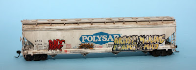
The other car I will present here is a large, four-bay covered hopper, ACFX 97604, operating under lease from American Car & Foundry’s lessor, ACFX, and lettered for Polysar resins..

The large, smooth sides of this model are as attractive for large graffiti pieces as are the prototype covered hoppers, because they offer a large, unimpeded canvas for “creative expression,” as we may term it (certainly the prototype “writers,” as they call themselves, would use the term).

On the left side of the car, I applied the large piece (“can’t be stopped”) from Microscale set 87-1535. The smaller piece at the right (the word “look”) is a paper overlay, taken from page 136 in the excellent reference book, Freight Train Graffiti, by Roger Gastman, Darin Rowland, and Ian Sattler (Abrams, New York, 2006), and applied as I’ve described earlier (see citations in the third paragraph, above).

Of course, the model as you see it above is weathered moderately, and some tags added with “Gelly Roll” pens.

On the right side of the car, there is again a paper overlay, this one created from a prototype photo of this piece on a similar car (I showed it in a blog post about the Cocoa Beach RPM meeting in 2017; a post you can see here: https://modelingthesp.blogspot.com/2017/01/cocoa-beach-2017.html ). I have adjusted the size of the image, along with squaring it up in Photoshop, for this overlay (at right, reading “artists making foamers mad”). The two smaller pieces are from T2 Decals, Graffiti Set #1 (you can see their growing line of graffiti decals at: https://t2decals.ecrater.com/c/135116769/graffiti-decal-series ).

These two cars gave me another chance to apply paper overlays, a technique I now feel fairly comfortable with. I like that it allows inclusion of graffiti I have photographed myself, with minimal effort. And I think both these cars benefit from this flexibility.

Tony Thompson

Thursday, April 1, 2021

Waybills, Part 83: interesting examples

 Over the years, a number of people have been kind enough to share with me copies of prototype waybills in their possession. By far the most extensive of these have been bills from the collection of Andy Laurent, and I am grateful to Andy for his generosity in sharing these. This post gives examples of two interesting waybills. 

Incidentally, if you would like to examine earlier posts in this series, the simplest way to find them is to use “waybills part” as the search term in the search box at right.

To begin, let me show a waybill from a very small railroad, the Raritan River. It was a 20-mile railroad in and around South Amboy, New Jersey,  and owned no freight cars in interchange service. It interchanged with both the Pennsylvania Railroad and the Central of New Jersey in South Amboy, and largely provided local switching service; in 1953, it listed 8 locomotives in service. 

Despite its small size, and unlike many small or switching roads, the Raritan River did issue waybills. This is an example from the Laurent collection; note that like so many bills, it’s creased down the center from conductors folding it. (You can click on the image to enlarge it if you wish.)

Note several interesting things about this waybill. First, the load was shipped in a New York Central box car, no. 41192, a 50-foot single-door car of 50 tons capacity. The cargo is shown as a carload (C/L), and comprised calcium silicate and asbestos in flat sheets; and it is noted that the shipper counted and loaded the cargo (SC&L). The car was weighed at Parlin, New Jersey, with the weight is given as 72,700 pounds. Notice that the original freight charge has been corrected by hand.

It was interchanged to the CNJ at South Amboy, and routed to Taylor, Pennsylvania for transfer to Erie Lackawanna. Via EL it went to East Buffalo, New York for interchange to C&O (Pere Marquette District) and taken to Ludington, Michigan for car ferry transportation across Lake Michigan to Kewaunee, Wisconsin and the Kewanuee, Green Bay and Western, and finally to the Ahnapee & Western for delivery to Algoma, Wisconsin.

Here’s another waybill that was interesting, at least to me. It’s from the Oregon Electric Railway. The OE began operation in 1908 as a connection between Portland and Salem in Oregon’s Willamette Valley (as locals always say, “Willamette” rhymes with “dammit”). Only two years later, in 1910,  it was purchased by the Spokane, Portland and Seattle, and the line was extended to Eugene in 1912. Though electric operations ended in 1945, the OE survived well after the BN merger, still as a wholly owned part of the BN system.

Many railroads with such subsidiaries had the local agents use the big road’s waybills, but many did not. The OE is an example, as you see in the waybill below.

This waybill illustrates a number of things. First, of course, is the OE header at the top. Second, the cargo of plywood from U.S. Plywood’s plant in Eugene, to the Algoma, Wisconsin Division of U.S. Plywood, is only shown as a carload (C/L), and the notation on the bill states “do not weigh,” in light of the Weight Agreement stamp (large round stamp at upper right). The load is being shipped in C&O 16186, a 50-foot double-door box car. Such a car is a free-runner, of course, and thus it’s not peculiar that a C&O car is being loaded in Eugene, Oregon.

Routing is as follows: OE to Willbridge, Oregon, thence SP&S to Spokane and interchange to Northern Pacific. Then NP takes the car across its Northern Transcon to interchange with C&NW at Park Junction (Minneapolis), thence to the Green Bay & Western at Merrilan in central Wisconsin, then to Green Bay, and via the KGB&W and Ahnapee & Western to Algoma.

Of course, as a modeler of the western U.S., I felt I really needed to have an OE waybill for use in layout operating sessions. This is simple to do, just graft the OE header seen above onto the standard AAR waybill form (admittedly not exactly the same as the OE form). Here’s how it looks in my model form when filled out (note the weight stamp is literally exactly the same, even the agreement number):

I feel like I have learned a lot about how waybills looked and what information was used in filling them out, by examining a number of the bills Andy Laurent was kind enough to share with me. And I expect to continue to learn in the same way. Sometimes, as with the OE bill shown in this post, I even gain another model waybill, but the Raritan River feels just a little too remote for me — maybe I’ll wait and see if it grows on me <grin>.

Tony Thompson