Saturday, January 29, 2022

Improving a freight car, Part 2

The previous post on this topic took up the challenge, describing what I might typically do to upgrade a car kit to my usual layout standards. The kit is an InterMountain 12-panel box car kit. You can read my preliminary analysis of needed changes and upgrades in that previous post, which is at: https://modelingthesp.blogspot.com/2021/12/improving-freight-car.html .

These particular InterMountain kits do not include car weights. I decided to use what I often use for house cars, a pair of 5/8-inch steel nuts, glued inside with canopy glue. This has proved a secure attachment, and adds close to the needed two additional ounces to meet NMRA weight standards. (I might mention that I doubt there is any great significance to the exact NMRA weight values, but I do think that consistent car weight matters in operation, so the NMRA standard is as good as any.)

I should add that before adding the weights, I drilled and tapped the bolster centers for 2-56 truck screws (discard those self-tapping screws!). This makes the screw holes evident inside the car body, and prevents gluing the weights atop them. And since the doors will be glued on, no need to paint the weights.

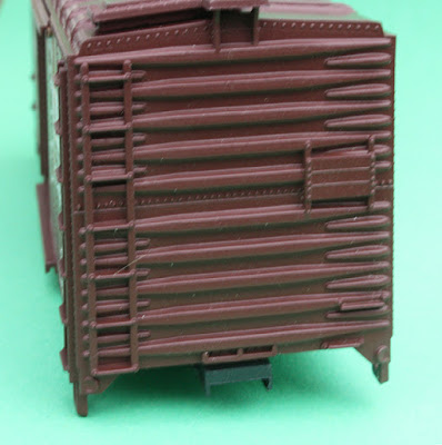
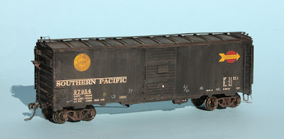
I mentioned in the previous post that the kit side doors were not the correct style, but that I had replacements. Here are the replacements, with the kit placard boards and route card boards in place.

I also mentioned using a Kadee Morton running board to replace the kit’s incorrect board. This has been received. But it isn’t quite the same color as the InterMountain kit parts. So both the running board and the new doors called for a paint match to the IM molded color. Like many modelers, I have a considerable stash of red-brown paint colors, of many brands. The closest match here was Tamiya “Hull Red,” no. XF-9.

The kit coupler boxes are intended to be glued in place, including box covers. I learned long ago that this is a prescription for coupler maintenance problems, so I clipped off the posts on the box covers, drilled a hole centered on the post location, and tapped both box and cover (and car body) for 2-56. This isn’t a great coupler box, and a Kadee box might be better; but I did use the kit box to install Kadee #58 couplers.

Incidentally, one advantage with making the kit coupler boxes removable, and attached with a screw, is that if any problems later develop with these boxes, they would be readily replaced with Kadee boxes. 

Lastly, in changes to kit parts, I discarded the kit’s molded plastic wheelsets intended for the trucks — this type of wheel has long been banned from my operating equipment — and replaced them with InterMountain Code 88 wheelsets. These metal wheelsets look better, run better, and don’t collect dirt.

I should mention that although these InterMountain trucks resemble the ASF A-3 trucks actually applied to the prototype cars, they are not quite an A-3, but I decided to use them, since they are close. For a great deal more on this point, you may wish to consult Richard Hendrickson’s 2014 article on model trucks (there’s a link at: http://modelingthesp.blogspot.com/2013/07/another-update-to-richard-hendricksons.html ).

With these modifications, I was ready to proceed with the more mundane aspects of the kit assembly, most of which I won’t bother to describe, but will then carry out weathering and other finishing details. Those will be described in a future post.

Tony Thompson


Wednesday, January 26, 2022

What’s an operating plan?

 From time to time I read, or hear about, someone’s layout Operating Plan. Of course this can be whatever you want it to be, from simple to complex, but I recently reviewed an online discussion on the topic, and thought I would offer a few thoughts here. These somewhat parallel and supplement a prior post on the topic (see it at: https://modelingthesp.blogspot.com/2018/09/thoughts-on-operation.html ).

Not much more than 30 years ago, you could visit a layout, as I did, and be told that the Plan for the evening was this: “Tony, you run the reefer block, and Carlos can follow with the coal train. When he gets in, I’ll run the passenger train.” And no, I’m not making this up. Of course, many layouts were different then, and even more are today.

I feel obliged to point out that fully 80 years ago, when the third printing of the 1942 book, How to Run a Model Railroad, by Al Kalmbach (writing as “Boomer Pete”), came out, there were already people making up timetables and detailed schedules, and trying to operate a layout in conformance to such Plans.  The cover shows how the serious model railroader would look:

And only a few years later, the famous Delta Lines layout of Frank Ellison received detailed coverage in a six-part series in Model Railroader magazine (reprinted in 1965). Ellison and his operating crew were entirely serious and had a detailed scheme for running the layout. The Model Railroader issue for November 1955 contained a full article about a Delta Lines operating session.

In the photo above, that’s Ellison himself at right, and operator John Kolp at left, each using a “cab” control panel for the trains they are each operating, carrying out a meet. Both wear headsets to permit talking to the dispatcher. The article shows numerous photos of operating positions around the layout, clearly comprising a complex and detailed operating session.

But the hobby continued to feature, as seen in innumerable photographs in Model Railroader and Railroad Model Craftsman magazines, the solo operator at his master control panel. To be sure, this permitted a layout owner to operate his entire layout himself; but it made it difficult to provide roles for visitors. This 1952 Kalmbach book cover is  good example.

So obviously any Operating Plan has to reflect how the layout was designed and built. A layout with controls such as the one shown in the photo above is not going to work well for “walk-around” operation. Today, with DCC hand-held throttles in widespread use, it may be hard to remember how many years even the Frank Ellisons had a challenging electrical design problem for local train control.

That naturally leads to scenes like this one, from the cover of the Model Railroader issue for December 1950, showing the  layout of the Metropolitan Society of Model Engineers, in Union Station, Washington, DC. Naturally, all are wearing their engineer’s hats, and the man in charge at the master control panel has the obligatory pipe.

Now of course this is a posed picture and wouldn’t reflect any particular Operating Plan; but it is symptomatic of how model railroads were usually conceived and operated for a lot of years.

Any layout that was built primarily for operation (and let’s remember, many were not and are not — emphasizing perhaps scenery, or a display of structure or locomotive collections) still needs to have a Plan of how it’s to be operated. This can cover quite a range of options (including the “Tony, you run the ...”).

Probably the most comprehensive (and modern) source of discussions of operating  schemes is the book, A Compendium of Model Railroad Operations, published by the OpSIG (Operations Special Interest Group) in 2017 and still available for purchase at their website, https://www.opsig.org/assets/compendium.pdf . I reviewed this book when it came out (here’s a link to that post: https://modelingthesp.blogspot.com/2017/06/the-excellent-new-opsig-book.html ).

Starting with a prototype timetable can certainly work, even for a freelance layout, since it provides a framework for trains that operate. Inevitably our immensely compressed physical depictions of the prototype require compromises, but a prototype flavor can be achieved. Whether timetable and train order (T&TO), CTC, or track warrants, a prototype-based system of train authority contributes to realism. Handheld throttles permit independent action in such a system.

To sum up, I think the most productive approach to an Operating Plan is to try and reproduce railroad jobs — having your visitors take on specific railroad assignments, and operate according to prototype railroad rules and procedures. This is what one encounters at the various operating weekends around the country, which I greatly enjoy, and it’s what I try to do in planning op sessions on my own layout. If you haven’t thought about this, give it a whirl. There are lots of resources out there to help  — from the OpSIG book, all the way back to Boomer Pete.

Tony Thompson


Sunday, January 23, 2022

“Blue Box” upgrading, Part 3

 In the previous post on this topic, I showed the two improvements that ought to come immediately with any Athearn “Blue Box” 40-foot box car: discarding and replacing the brake wheel and running board. You can find that post at this link: https://modelingthesp.blogspot.com/2022/01/blue-box-upgrading-part-2.html .  

Let’s now turn to the biggest visual problem with this model: the side door. On the prototype cars, the doors were practically the full height of the car side, as you see below on a Southern Pacific box car of 1937 AAR standard design (AC&F photo, SP collection). If you look carefully, you will see that the lower door track is actually below the side sill (you can click on the image to enlarge it).

But the Athearn car is not like this. The reason stems from the design of the model. Athearn chose to place the car weight, a strip of plain-carbon steel, above the underframe, nicely concealing it from view, even at a slight upward angle from below. But that meant that the floor was on top of the weight, and raised up inside the car body, making the floor too high. 

Athearn also chose to make an operating door, and of course the floor should be flush with the door threshold. To make that happen, Athearn simply made the door shorter. Compare this view to the photo above; the Athearn door track is well above the side sill, and of course the door is visibly too short.


 (This model has the door “claws” removed — see more on that below — and wire grab irons and Tuttle sill steps added. )

 In addition to height, other consequences of the working door (which, it must be said, is solid, sturdy and reliable), are an oversize top door track, and a really big ledge to serve as lower door track — plus the infamous Athearn “door claws,” which slide in the lower door track. The claws are evident below.

What to do? Removing the upper door track (and filling the body holes), then replacing with a piece of scale 2 x 2-inch styrene strip helps. The Athearn lower “door ledge,” as it is known, can indeed be carved off, but then you need to add the row of rivets where the ledge used to be, and paint. Not too bad a task with Archer rivets or equivalent, but more work. Then place another strip of 2 x 2 where the lower track should be. But this is getting to be a bunch of work for a car with almost no prototype.

Back in the day, when there were few good after-market HO scale boxcar doors, modelers used to carefully cut up two Athearn doors, and splice the piece together to make a correct-height door. Then make a mold, and you could cast as many resin doors as you wanted. More work, of course. Today, there are lots of accurate, scale-height doors, so you can just replace the kit door.

But what if you really don’t want to carve off the ledge, replace rivets, and find a new door? Well, the least you can do is to slice off the claws, making the door look considerably better, and slice off half the width of the door ledge. Of course, now you have compromised well beyond ignoring the model’s end with almost no prototypes, because the door on the car side is far more obvious. 

But before I close, I have to mention a great irony in all this. Before the one-piece plastic body of the “Blue Box” kit, Athearn sold a metal kit for the same car. It actually had a correct 4/5 end for a 10-foot IH, and even had a correct-size side door. Here’s the end, and if the ribs lack some depth, there are at least the right number of them. The placard board is pressed into the end, but there are separate grab irons and (nicely made) ladders.

And here’s a side view. Compare to the prototype photo at the top of the present post. The door is pressed metal, so quite thin, and again, separate ladders, grabs, and sill steps.


Sigh. So Athearn really did know what one of these cars looked like. They just chose to do something else when they designed the plastic version so familiar in its Blue Box.

Tony Thompson

Thursday, January 20, 2022

“Overnight” box cars, Part 2

 In addition to the challenge in modeling the cars themselves that were used for the “Overnight” service, in their distinctive black paint schemes until 1956, there is an challenge in understanding how they were operated, referring of course to model railroads. The previous post described the car issues (see it at: https://modelingthesp.blogspot.com/2022/01/the-overnight-box-cars.html ). 

The high-volume “Overnight” service was between Los Angeles and San Francisco, and of course, as the name indicates, was an overnight service. But other cities in California, Oregon and Arizona were also served. In addition, smaller cities along the lines were served by dropping off a car, from which PMT trucks could make efficient local deliveries. The ad below sums it up (from Journal of Commerce, Oct. 17, 1935, courtesy John R. Signor). To read the smaller print, click on the image to enlarge.

This 1935 ad mentions that local pickup and delivery were through local draymen working for Pacific Motor Transport, while trucking to other cites was by Pacific Motor Trucking (PMT). These entities were soon combined into one organization, PMT.

This was almost always an express LCL (less-than-car-load) operation, and SP promoted it that way. For a vivid illustration, the photo below shows an “Overnight” car being loaded in November 1938 at Los Angeles (SP photo N-1699-1, DeGolyer Library). Many of these items could be headed to multiple different merchants in the destination city.

So for layout operation, unless you model the Coast Route main line, and can operate your layout in darkness, the natural environment of the full “Overnight” trains of black box cars, what parts of this service could you model? Obviously, you could model PMT trucks doing deliveries in almost any town in Oregon, California or Arizona, and I do that too. 

For a single example, I have models of PMT trucks, mostly of the delivery variety, that appear in various places on the layout from time to time. An example is below, a van heading up Chamisal Road in my layout town of Shumala, at photo center. This likely has come from San Luis Obispo, some 25 miles distant, and is making a local delivery in the area. (The model truck was painted by Jim Elliot.)

Of course, most of us want to model the rail part of the service. One possibility, though perhaps not terribly interesting, is that individual cars would occasionally be spotted for delivery outside the major cities (in my case, Los Angeles and San Francisco), and so might be headed back to one of those cities when unloaded and made empty. So an individual “Overnight” car in a passing freight, evidently empty, is one option.

A possible on-layout destination is the team or house track. I described this service in an earlier post (see it at: https://modelingthesp.blogspot.com/2015/10/operations-non-rail-served-customers.html ). This permits an occasional “Overnight” box car to be spotted on the layout, presumably with a single “hot” cargo rather than an assortment of LCL like the photo above of the boxcar interior. 

Under that scenario, you might model something like the scene below, which shows an “Overnight” car on the house track in my layout town of Ballard.

My own conclusion is that scenes like the one above ought to occur relatively rarely, as most “Overnight” service, in the form of LCL, would be delivered by PMT trucks in areas away from major division cities like San Luis Obispo. But yes, I do occasionally have a local spot of an “Overnight” car in an operating session.

Tony Thompson

Monday, January 17, 2022

“Blue Box” upgrading, Part 2

 The subject of this post is a little changed from the previous post, in which I identified what the old “Blue Box” Athearn 40-foot box car is, and is not. It is modeled with a sharp-corner Dreadnaught end for a car with 10 feet, 4-inch inside height, a quite unusual combination of characteristics. You can read that post at: https://modelingthesp.blogspot.com/2022/01/upgrading-blue-box-box-car.html .

In the present post, I turn to a different question: let’s imagine that you grant that the model has practically no prototypes, but you want to use it anyway. What would be done in upgrading it — assuming, of course, that you see any shortcomings in the model as it comes in the box. 

I would begin with what I think is an underappreciated aspect of our model freight cars, the roof. Most areas of nearly all model railroad layouts are at a height providing an excellent view of the car roofs. So any shortcoming on car tops is unavoidably obvious. 

Athearn for many decades provided a molded plastic running board representing a steel-grid running board, though doing so rather poorly, as it has hardly any three-dimensional relief on its upper surface. Back in the day, it was also disturbing thick, approaching a scale foot, but in more recent years it has decreased to about 6 scale inches, still 4 or 5 times the thickness of the prototype.

Accordingly, my very first recommendation with the “Blue Box” box car is to throw away this running board. Until after World War II, nearly all 40-foot steel box cars had wood running boards, and these are easy to model by replacement, with stripwood or styrene strip. Below is an example (with no corner grab irons yet installed, but some paint failure depicted).

After World War II, new box cars all received steel running boards, and gradually older cars got them too, whenever they were in the shop for any substantial work. This model, with its sharp-corner Dreadnaught end, is one of those cars that would later get a steel running board. There are lots of these available, from the nice Kadee molding, to several etched-metal versions from Plano and others.  Any one of them is greatly superior to the original Athearn kit running board.

I would immediately discard a second Athearn part that is so bad it really deserves a place in the all-time list of terrible freight car parts: the brake wheel. Not only was it almost always supplied unpainted, so its black color would jump out against almost any paint scheme, but it is a truly awful molding, greatly oversize (an HO-scale man couldn’t even get a hand around the huge rim), and an almost unrecognizable representation of the rest of wheel (was it supposed to be Ajax?).

Tossing this part should be barely seconds behind tossing the running board. And just about any HO scale brake wheel in the history of the hobby would be an improvement, so choose what you like. Nowadays, I use the superb Kadee brake wheels. Years ago, I used the Walthers white-metal Ajax wheels, not great parts but an immense improvement over the Athearn part.

Before continuing, let me mention one more aspect of the Athearn end visible above: the brake step. It is very narrow, possibly due to molding limitation, and there are no diagonals supports below it. The width is easy to correct: just scrape the edge of the existing step to remove paint, use styrene cement to add a length os scale 2 x 4-inch styrene strip, then add diagonal supports underneath with scale 1 x 2-inch strip. Along with an ancient Walthers Ajax wheel, it can look like this: (you can click on the image to enlarge if you wish).

This is admittedly a minor improvement, and evident in the photo above are the cast-on ladders and brake staff. But the improved brake step catches the eye and distracts the viewer from the other defects. Note also that on the model above, I’ve replaced the very poor Athearn molded sill steps with A-Line metal steps. More on that later.

So if you do nothing else in making an Athearn “Blue Box” box car a little better, do replace the running board and the very poor kit brake wheel. You already have a better model and one that is less obviously of “Blue Box” heritage.

Tony Thompson

Friday, January 14, 2022

Upgrading a “Blue Box” box car?

 I recently received a fascinating suggestion: why not discuss the terribly familiar Athearn “Blue Box” box cars, of both 40-foot and 50-foot length. The questions would be these: what was the prototype of those models (if there was one), what can be done with them, and would it be worth the effort?

Let’s start with the famous box. It’s shown at right below, and sure enough, it definitely does have a blue color, with the predecessor Athearn box, used for many metal car kits, at left.

I’ll begin with the question, does the 40-foot model have a prototype? One way to answer that is to look at the car end. The model end is an early Dreadnaught design, and has sharp corners. Some will tell you that this makes the car an AAR 1937 standard box car. Well, let’s look at the prototype end first. The photo below is a Pressed Steel Car Co. view of an SP 1937 AAR car.

Note that the end has a 4/5 configuration, that is, 4 ribs in the top section, over 5 ribs in the lower section of the end. Now let’s look at the Athearn end. As you can see below, it’s a 5/5 end. How did that come about? The photo above shows that there really isn't room for a fifth rib at the top of the end. How did Athearn arrive at this end design?

 The standard 1937 AAR box car had 10 feet, 0 inches inside height (IH). The SP prototype car shown above has that inside height. But around the beginning of 1939, two railroads chose to buy 10 ft., 4 inch IH box cars, and they had sharp-corner ends like the Athearn end — and they had 5/5 ribs on their taller ends. Richard Hendrickson did exhaustive research on this and could only find those two railroad buyers, the larger of which was the Soo Line, the other one (which I’ve forgotten) was considerably smaller than the Soo.

It should be mentioned that at about the time of the Soo purchase, Standard Railway Equipment Co., maker of the Dreadnaught end, made an improvement, adding a W-section corner post to the car ends, and replacing the sharp corner of the 1937 end with a curved corner. So although it’s true that a fair number of 1937-type cars with IH greater than 10 feet were built during 1939–1942, they had W-corner post ends, not sharp-corner ends. 

So yes, the Athearn car, just on the simple basis of its end configuration, has at least one railroad prototype. The model has a whole raft of other problems, but the main point to recognize is that of the many, many paint schemes applied by Athearn to this model with a 5/5 sharp-corner end, all but one (maybe two) are wrong.

Now I realize many modelers will say, “Hey, I don’t count end ribs, in fact I really don’t even look at car ends much, and I’m not impressed with this 5/5 story.” To which, I can only reply, I was just answering the question, does the car have a prototype? If you don’t care whether it has one, you may then want to read my following posts about various upgrades that can be done to this Athearn model.

Tony Thompson

Tuesday, January 11, 2022

The “Overnight” box cars

 There is a fairly long and complicated history behind Southern Pacific’s “Overnight” service, and I won’t really go into it in this post. For those who would like to examine details, I wrote a series about Pacific Motor Trucking (PMT)  in the SP Trainline (SP Historical & Technical Society), issues 43, 44, and 46 (1995-96). Essentially, PMT began in April,  1933 as an SP subsidiary, created for the purpose of owning and operating trucks.

The idea behind the “Overnight” service was for PMT to provide store pickup at origin, and delivery at destination, with SP trains connecting the two points. This provided “door to door” service. The first trains simply used baggage cars, but in October 1935, the first “Overnight” trains went into service, and in summer 1936 began to use specially-painted black box cars. An example is below, Class B-50-15 no. 9366 (Robert McFarland photo, Bayshore Yard, 1940, Arnold Menke collection).

Here the black car has Daylight Orange stripes along the top and bottom of the car side, and outlining the door. All lettering is also Daylight Orange. (Note that this use of Daylight Orange paint preceded the introduction of the Daylight trains themselves in March, 1937.) But this paint scheme disappeared during World War II, when “non-essential” trains were discontinued.

Of course, to many modelers and railfans, the “Overnight” scheme that is most familiar is the 1946 version, still with a black body but with yellow SP emblem and yellow arrow across a red ball. (The scheme was also applied to some of the Class B-50-15 and -16 cars.) Here’s a rare color photo, from the Bruce Petty collection:

Though it’s not obvious in the photo above, all the car sides of Class B-50-24  had so-called “Alternate Center Riveting,” or ACR, a row of rivets in the center of each side panel, indicating an extra post inside the car at that point, added because of the thinner and thus less-stiff side sheets. After October 1956, a silver scheme was adopted which showed the ACR well (Wilbur C. Whittaker photo, Dunsmuir). You can click on the image to enlarge it if you wish. This photo also shows clearly  the wide-seam door used on these cars.

For more on the history of these cars, you may consult Chapter 12 of my book about SP box cars, Volume 4 in the series Southern Pacific Freight Cars (Signature Press, revised edition, 2014.)

There have been a great many model versions of the black box cars, in all scales, on a variety of 40-foot bodies, the great majority of which were not accurate. There are two major exceptions in HO scale. The first, perhaps surprisingly, is the old Athearn metal car in the Overnight scheme. 

You have to give Irv Athearn credit here: rather than just slap the black scheme on their regular 40-foot box car, he had new ACR sides made, and new ends (the ends aren’t great but they do represent an “Improved Dreadnaught” postwar end, instead of using their regular prewar end). He even modified their regular door, which has rivets in the two seam panels, and removed the rivets to give it a welded look. Here’s one of these cars that I have.

These show up frequently with on-line sellers, so they certainly can be acquired if wanted. The only real defect that calls out for replacement is Athearn’s representation of a wood running board.

A more modern version of the prototype is the Sunshine model, with a better door and better ends, along with a correct metal-grid running board. My model is weathered more than the model you see above; but look again at the prototype photo of SP 97937, above.

Note that my Sunshine car has the spelled-out “Southern Pacific” reporting mark, though most cars just had the initials SP. The cars were in production during July to September, 1946, and it was not until the tail end of production, during September, that builder Mt. Vernon made the change to the new (1946) spelled-out reporting mark.

There are also model railroading challenges in how one might operate these cars (beyond, of course, running full trains of them in darkness). I’ll explore those in a future post.

Tony Thompson

Saturday, January 8, 2022

Another freight car saga

 From time to time, I have related in these posts various sequences of events surrounding a few freight cars. Sometimes they even rise to the level of a “saga.” This is one such, this time an HO scale brass model of a Pennsylvania Class F38 flat car. The model was built by Woo Sung in Korea and imported by Rail Classics. Most photos show the models factory painted. 

I don’t know whether this particular model was originally painted or not, but it came to me painted for a road other than PRR.  The model’s owner, my friend Paul Weiss, wanted the car to be correctly lettered for its true owner. So my first question would be, what’s the prototype?

There were just two cars in this class, built at the PRR shops in Altoona, PA in 1954, distinctive four-truck flat cars with a 500,000-pound capacity. That was accomplished with four Buckeye 6-wheel trucks under span bolsters. The body was a one-piece steel casting by General Steel Castings (for more about them, see my post at: https://modelingthesp.blogspot.com/2021/11/the-gsc-flat-cars.html ). 

For information about this or any PRR flat car, I consult the superb book by Elden Gatwood and Al Buchan, entitled Pennsylvania Railroad Flat Cars (Pennsylvania Railroad Technical & Historical Society, Kutztown, PA, 2008), which I’ve mentioned it before: https://modelingthesp.blogspot.com/2021/01/another-simple-resin-kit.html , and will say again, it’s one of the great freight car books. 

The problem one immediately recognizes with trying to re-letter a model of the F38 flat car is that the side sills are so narrow, that not just any decal set can work. Here’s a PRR photo of the first of the two cars, PRR 470246, taken from the book shown above. (You can click on the image to enlarge it if you wish.)

Here’s another photo from the book, that may make the lettering a little more obvious (note that “DO NOT HUMP” is permanently stenciled on the car, just at the near end of the side sill). The loads, from Mesta Machine Co. of Pittsburgh, appear to be crosshead castings or foundations for a mammoth press.


Shown below is the HO scale model, and the welded, smooth deck is evident, with numerous tie-down points for bolt-through or steel strapping attachments. It’s freshly repainted with Tamiya “Fine Surface Primer,” Oxide Red, reputedly a good version of PRR “Freight Car Color.” You can also see (if you enlarge), along the side sill, the numerous cast-in ribs of the prototype. These would prove a challenge for decal application.

I was quickly able to determine that there are no decals available. My friend, Bruce Smith, past president of PRRT&HS, confirmed this finding, but copied John Frantz of Mt. Vernon Shops on the messages. John had prepared any number of PRR decals over the years, and so the F38 was thrown up as a challenge. John decided to give it a try but warned it could be awhile. So the model has been sitting alongside my workbench for some time.

But just recently, John’s decals arrived. These are essentially a custom decal, not part of his regular stock, but they suit the brass model perfectly. What a pleasure to have every bit of the prototype lettering available! But as mentioned, fitting the decals to the narrow sill and its ribs did prove a challenge. Here is the car, PRR 470246, as lettered, but without weathering yet.

I used my ordinary process of acrylic washes to weather this model (see the “Reference pages” at the top right of the present post for more information on materials and procedures). The last step was a coat of flat finish. Here you see the car in mainline freight train (just trying out its operation), passing the Shumala depot on my layout.

This has been an interesting and challenging project, and I am grateful to John Frantz for helping out with the decal problem. Now the car heads back to its owner, Paul Weiss, and his Central Vermont layout.

Tony Thompson

Wednesday, January 5, 2022

Modeling engine servicing

Most layouts include some kind of engine terminal, where such servicing as refueling, adding sand, and minor repairs could take place. Sometimes a very complete roundhouse or diesel shop is modeled. But however much or little is included, there are operational considerations. That is the subject of the present post, not the modeling of the terminal facilities themselves. 

On my own layout, I have modeled the engine facilities for my mythical branch line, the Southern Pacific’s Santa Rosalia Branch, as including a roundhouse and turntable, along with fuel and water facilities for steam locomotives. This terminal, and many of its details, including work carts, fire hose boxes, and other features, were described in a Model Railroad Hobbyist article, in the issue for August 2017. That issue is still available to read on-line or download for your use, for free, at www.mrhmag.com .

The largest feature of this engine terminal is, of course, the roundhouse. I built the Banta Modelworks kit, which is an accurate representation of SP’s Port Costa, California roundhouse, and added a machine shop to the rear of the structure (see a description at: https://modelingthesp.blogspot.com/2014/01/shumala-roundhouse-part-3-machine-shop.html ). Here’s an overall view, with Consolidations 2575 and 2592 at the house.

As you can see here, there are “garden tracks” on either side of the roundhouse, exactly as was the case for the prototype Port Costa house. The large steel water tank is a Harriman standard design, and was the source of water for the water column at the fuel spot.

For operating sessions, one could move locomotives into and out of the roundhouse, but in reality a hostler would perform those jobs, not a switch crew or road crew, so in my sessions, I have always had the locomotive that’s on duty today positioned at the fuel/water spot, thus freshly readied to depart.

Here is a view including the machine shop (added at left), and the foreground track is for deliveries of company parts and materials to the shop.

What is often most noticed, though far smaller than the roundhouse, is the fuel and water area. The basic part of it is the fuel and water columns, shown here with no other details. The background industry is an Associated Oil Company bulk oil dealer.

But of course an area like this is used for a number of inspections and last-minute adjustments of engines going into service. So more usually the area looks like you see below, with workmen, ladders, and work carts. This is an arriving engine, about to get the oil bunker topped off, and then to get the sand box refilled. SP 2829 is shown on the inbound engine track, and presumably already had its water compartment filled at the water column.

I have scratchbuilt a sand house for this terminal, following the SP standard plans, with dimensions chosen to fit my location. A description of that project was in a “Getting Real” column in Model Railroad Hobbyist, the issue for January 2021, in the Running Extra segment. It’s barely visible in the photo above; here is a closer view with a different inbound locomotive.

So in setting up an operating session, I pull the locomotive from the roundhouse, if it is not already standing at the service area, and move it to the outbound engine track. Normally it will be oriented tender-first, as that is how most crews chose to run outbound on the branch. There being no turning facility on the branch, one direction was always tender first.

A common situation at the opening of an operating session, then, is that the road locomotive is waiting on the outbound engine track (at left), while the switch crew is finishing putting the train together. In the view below, the switcher has just picked up a reefer that’s been pre-iced, and is about to tack the caboose and that reefer onto the rest of today’s branch local, waiting on the track behind the ice deck. 

Today’s road engine, SP 2829, stands on the outbound engine track at left, where the engine crew will take over from the hostler and bring the engine down onto the train. But before that can happen, the switcher will have to pull the entire branch train off to the left of the photo, so the engine can take its place on the head end.

I think it is useful in an operating session for a crew to understand that engine service is part of the preparation of a train, and they take control of their locomotive where it has been made ready for service, not just conveniently encountered at the head of the train, ready to go. So the foregoing describes what I do instead.

Tony Thompson

Sunday, January 2, 2022

Richard Steinheimer, Part 3

 In Part 2,  I showed a few of the Richard Steinheimer photos I particularly like, and tried to explain what I thought makes them distinctive. I also hoped my selection would illustrate some of the great qualities of Stein’s photography, as it is compared to other railroad photographers. That post can be found here: https://modelingthesp.blogspot.com/2021/12/richard-steinheimer-part-2.html .

I also mentioned in the prior post that I have visited the DeGolyer Library at Southern Methodist University, three times in all, and have ordered a fair number of prints from those negatives. I have paid the Library a fee for publications rights of them all, but always also asked Dick for his permission as well, even though the negatives belong to the DeGolyer. The last thing I would have wanted to do, was to use one of the photos in a way that Dick would not have approved.

Among Steinheimer’s many attributes was his knack for portraying the train in its environment. Often this meant the train being a rather small proportion of the image, not at all a typical “railfan” image. An example is this 1964 photo of a Milwaukee Road four-car local train in Montana, west of Bozeman, with the NP line in the foreground. I think it safe to say that few railroad photographers would have composed an image this way.

Another characteristic of Dick’s images was that often he would hike to relatively inaccessible places to get an angle he wanted. He also liked to work in difficult conditions. I remember him saying one time in a talk, “Ever notice how when the first snowflake falls, all the other photographers disappear?” He, of course, got some great images in bad weather. Below is one of my favorites, which was shown in the Electric Way book. Those are double-headed “Little Joes” on the point, above Falcon, Idaho in 1972, and Dick stated that it was snowing steadily.

I bought this print from Stein at a Winterail, and having his signature on the back makes it especially fine.

Another photo I have always liked is this 1960 image inside the caboose of the eastward Coast Merchandise train (the “Overnight”), about to depart, and the conductor and brakeman (both naturally wearing hats) are going over the waybills. A great scene from a bygone era.

Finally, I’ll admit that as a modeler of SP’s Coast Route, I really concentrated on Dick's images of the Coast when examining negatives at the DeGolyer. Many of them were published in my book with John Signor, Coast Line Pictorial (Signature Press, 2000). I might begin with a good example of his ability to portray employees at work. In the photo below, a workman is just taking down the blue flag, hooked to a loop on the cab side, to release this helper on the westward “Mail,” no. 71, led by 2-10-2 helper no. 3711, about to depart San Luis Obispo. (You can click on the image to enlarge it if the blue flag isn’t evident.)

Another favorite is below, taken in the same area as the one above. It’s the two sides of the “Coast Mail” meeting at San Luis Obispo in 1953, westward No. 71 at right waiting to depart behind 2-10-2 helper no. 3666, and arriving No. 72 just coming into view at left, behind Class Mt-1 no. 4307. Both the engineer and fireman on the helper are watching No. 72.

These few photos, of course, barely scratch the surface of the tens of thousands of negatives Dick took of railroad subjects in his lifetime. I just hope they convey my appreciation for all he accomplished. 

Tony Thompson