Friday, May 29, 2015

Another approach to tank car platforms

Platforms around tank car domes (or valve bonnets, on high-pressure or ICC-105 cars) have been a challenge to modelers for some years. The most familiar models, such as the Athearn blue-box “chemical” tank car, have a poorly rendered attempt to look like steel grid, not only far too thick but also not “see-through.” Until 1948, when “other than wood” walks became mandatory for tank cars, such platforms were commonly wood, not steel grid, so older tank cars may well not have the steel grid in any event.
     Before continuing, I should also repeat what I have often said, both in this blog and in many clinics, that the Athearn “chemical” tank car has a grossly oversize valve bonnet and platform — they are about S scale, not HO scale. The valve bonnet can be replaced, with the correctly sized Precision Scale brass part, number 31005 (I have shown that replacement earlier, at this link: http://modelingthesp.blogspot.com/2010/12/upgrading-old-models-2.html ), or with other replacements, such as Frank Hodina’s resin bonnet (see this post: http://modelingthesp.blogspot.com/2015/05/kitbashing-anchor-lpg-tank-car.html ).
     The platform, however, is the subject of the present post. About a year ago, I posted a description of my (not very successful) effort to kitbash the Athearn platform into a smaller wood-planked version, with shorter posts, which is at: http://modelingthesp.blogspot.com/2014/05/upgrading-tank-car-dome-platforms.html . By “not very successful,” I mean that the platform still had pretty big posts, and was a real pain to cut up and reassemble. You can see it on the foreground Dow car in this photo (the photo is repeated from that previous post). Behind it is a stock Athearn car with its huge bonnet.


The modified platform posts on the Dow car are about two-thirds the height they originally were, but are still a little too tall, and are still way too thick. And although the platform is about the right length (parallel to the rail), it is too wide. There has to be a better way.
     I decided to try something entirely different with the Hooker car that is in the background of the photo above. First, I discarded the Athearn platform entirely. I learned my lesson by trying to rebuild the one on the Dow car. I then used a razor saw to slice off the Athearn valve bonnet, and filed the cut surface to match the tank. This leaves some odd ribs and round depressions on the tank top, which need to be cleaned up. I shaved off the offending parts (note the thin black stripes right at the edge of the orange areas below — you can click to enlarge the image), and filled the two depressions with Squadron Green putty.


     I intended to keep the wide black stripe on the body, but needed to match the body color for the areas I had repaired. Eyeballing the color, I tried a mix of 2/3 Daylight Red and 1/3 Caboose Red (old Floquil). This matched fairly well, though the mix is perhaps a trifle too red; straight Daylight Red might have been better. But since the car will receive some weathering along its top surface, this isn’t serious.


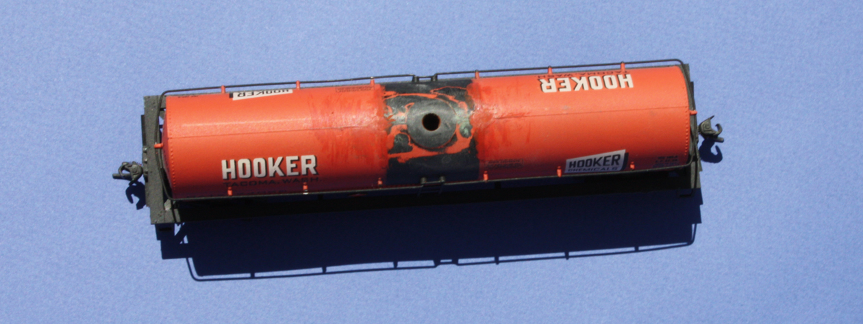
     I now assembled the two parts of a Hodina valve bonnet and attached it to the tank with canopy glue. This bonnet is barely half the diameter of the Athearn molding. I show it unpainted for clarity, but it will be black along with the body stripe, as was Hooker practice (the original Athearn bonnet, with its orange sides, does not match any Hooker photo I have seen).


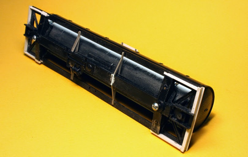
     Now for a platform. I decided to try the platform parts for the Atlas kaolin tank car, which are sold separately. This is their part  number 9170013, and is called an “upper platform with handrail.” At first glance, it is the wrong shape for the tank car I am looking at, though delicately molded and with see-through grid areas:


But since these are inexpensive platforms, one can use more than one to achieve the desired platform. I cut two of them, so as to use the “short end” of each, the left end in the photo above, thus creating the typical platform for a 1948 tank car. (That’s the built date on my model.) These platforms have mounting pegs molded to them, so I drilled no. 64 holes to accommodate them on the car, and used canopy glue to attach the two halves.


Compare the photo at the top of this post, for the difference in platforms. This platform is smaller than the black stripe, while the Athearn platform extended beyond it.
     Still, there may be some modelers who would say, “Well. c’mon, it still has about the same platform.” For a comparison, here are the Atlas part on the left (of which I used less than half) and the original Athearn platform on the right. Draw your own conclusions.


     This tank car now looks much better. What about the tank size? The Athearn “chemical” car is around 11,000 gallons size, which is all right for chlorine service, to which many Hooker cars were assigned, so the car size and lettering are all right in this case. This project was simple and yielded an improved Hooker tank car, and I’m happy with the result.
Tony Thompson

Wednesday, May 27, 2015

Pismo Dunes Road, Part 4

In the previous post, Part 3, I showed my trials of various ways to orient the street which intersects Pismo Dunes Road in East Shumala, to try and minimize visibility of the street heading straight into the backdrop (that post is at this link: http://modelingthesp.blogspot.com/2015/02/pismo-dunes-road-part-3-alder-street.html ).
      As I reported in that last post, I decided to very slightly curve and taper Alder Street, and went ahead with that plan. Here is the street after the shoulders were faired in with paper mache.


     Next I painted the shoulders and other unpainted or poorly painted areas with my standard dirt-undercoat acrylic color, Rust-Oleum “Nutmeg,” as I have shown in other posts. Just visible in the photo below is a small-radius fillet between the surface of Alder Street and the backdrop. (You can click to enlarge the image.) This helps hide the intersection of horizontal and vertical surfaces. Buildings have been removed in this view.


      The dark road surface you see in the photos above only depicts the primer color I applied to the bare styrene. I went back and painted the road a lighter color, typical of asphalt which has been in service awhile (whenever I need a refresher on how this kind of roadway looks, I just walk out in front of my house and look at the street). I used acrylic tube colors, predominantly Neutral Gray, with a little Titanium White to lighten it a little.
     The other thing needed in this scene is some suggestion that there are trees, bushes, or some kind of vegetation in the middle distance, so that the lowest angle view does not show the distant hills. I like to do this with acrylic tube paint, as I have shown in previous posts. Here is the revised scene, with the road a more nearly correct color, and various vegetation painted on the backdrop to show between the buildings and alongside Alder Street. Note also that I have cut off the bottom of the Caslon Printing Company flat and replaced the cut-off piece with a plain piece of foam core. As you can see in the top photo in this post, the original Caslon flat sat too far from the track. So what you see here is a revision of that flat in progress.


     My Caslon revision involved cutting off the bottom of the original flat, the part with the loading doors, moving it two inches forward to sit alongside the tracks, cutting a pair of 2-inch side walls from foam core, and covering the side nearer to the viewer with parts of the 3rd story of this building I removed originally in cutting it down. (You can read about that process here: http://modelingthesp.blogspot.com/2013/02/background-flats-2-kitbashing.html .) That’s another example of the old adage, “don’t throw stuff away if there is any conceivable future use for it.”
     Below is the new addition to the bottom of the Caslon building, with the two side walls done, and angled supports for a piece of foam core as the sloping roof. In this view, I have yet to apply a coping along the wall tops, which I made from  quarter-inch wide strips of 0.040-inch styrene, painted “Concrete.”


     The new addition also allows the background flat to stand up vertically without having to glue or tape it to the wall, which for me seems better. With the coping and roof in place, here is the entirety of the revision on the layout, completing the building. (You can click to enlarge.)


In the left foreground you can see one of my Walthers billboard structures, with an interchangeable ad for Lucky Lager beer in it. This idea was discussed earlier, at: http://modelingthesp.blogspot.com/2015/04/interchangeable-billboards.html . In addition, at lower right you can see my model of a California tankhouse, described in previous posts (such as: http://modelingthesp.blogspot.com/2015/05/building-california-tankhouse-part-2.html ).
     I'm happy to have a more believable loading dock at Caslon Printing, as before it was about 15 feet from the track, kind of a long reach for a plank to unload cars. And as mentioned it works better to support the building flat, too. My scenic locations along Pismo Dunes Road are coming along nicely. More later.
Tony Thompson

Sunday, May 24, 2015

Completing a Richard Hendrickson freight car

Last year, I made a number of trips to Ashland, Oregon, to help Richard’s widow, Sandra, with all the model railroad materials he had accumulated. The entire photo collection, estimated at 30,000 prints (more than 30 cubic feet), has now gone to the California State Railroad Museum, as have most of his railroad books; the balance of the books went to the new Railroad Museum at San Luis Obispo. His accumulation of styrene and resin freight car kits has been sold on-line, as have all his Santa Fe brass locomotives and rolling stock.
     On his workbench were a few in-progress projects. As I knew from previous visits, his usual procedure when working on a particular model was to scan and print the appropriate prototype photo from his collection, and then place that print in a clip above the workbench for easy reference. There was just one print which matched a project on the bench, a Wheeling and Lake Erie gondola. Here is the prototype photo. I am not certain of its origin (nothing was marked on the back of this work photo), but it looks like one of Howard Ameling’s prints.


I decided I wanted to complete this model out of respect for what Richard was doing.
     I don’t know an awful lot about the W&LE, but I was able to consult Richard’s card file. Obviously dating from before the convenience of home computers, he had long maintained this file of 3 x 5-inch cards, containing descriptions of cars in photos (many of them in his own collection, others in books), as far as he could research them. Here is the well-worn card file box.


The box label reads “prototype info.” And here is his card for the group of cars for the photo shown above (there are more data on the back of the card).


     In brief, the W&LE bought three batches of cars like this. The first batch, WLE 45000–45499, was built by Bethlehem Steel in February and March of 1945; the second group, 750 cars, WLE 45500–46249, by Ralston Steel Car in December 1946; and the third batch, WLE 46250–46749, by Bethlehem Steel in October and November, 1948. All were 41 feet, 6 inches long and 4 feet, 8 inches high inside (making them a high-side gondola) with 10-rib sides, and the same cubic capacity level full, 1842 cubic feet. So Richard had chosen a representative of 1750 cars, a big part of the W&LE fleet. It was not a new design for the W&LE, as they had built 1000 very similar gondolas in 1921. Ray Breyer helped me nail down some of these details that Richard had not noted.
     Richard had already modified the car body, I think from an old Mantua 10-rib model. He had added better Dreadnaught ends, along with underbody brake gear and the correct Ajax brake wheel. The grab irons had not been installed, though he had painted the car body and done the lettering, and had even made a start on denting and weathering the car sides. There was a note on the parts box, “TMW [Tahoe Model Works] B-1 trucks,” and since I have a pair of those on hand, I could add them. Both he and I had standardized on Kadee no. 58 couplers, and I added those. I used Westerfield 18-inch grab irons, a product I like and often use.
     Richard also had not added the car weight nor the floor, possibly because the floor did not fit quite right with the new ends. I did some cutting and filing to make the steel weight fit, and attached it with canopy glue, a superb adhesive for dissimilar materials like this weight and the plastic body. (If you’d like to know more about this glue, you can read my post which discusses its use, which is at this link: http://modelingthesp.blogspot.com/2013/05/a-few-words-in-praise-of-canopy-glue.html .)
     The plastic floor with the kit represents a steel floor, which the prototype cars did have. It was a little distorted, maybe from trying to make it fit (suggesting it might not be from the same manufacturer as the car body), but again, a little trimming and it was made to fit. Richard had already built a pipe load for the car, and since the load was in the box with all the parts, I simply added it too.


     You will note in this photo that Richard used his “denting” method on this model, using puddles of thick CA on the car sides to look like dents pushed out from the interior, a method he gradually improved over the years.
     Though I did not have to do much to complete this car, I enjoyed the feeling that I had finished something Richard had started, and that the car can now be part of my own layout operations.
Tony Thompson

Thursday, May 21, 2015

Building Guadalupe Fruit, Part 3

In my previous post, Part 2, I described my conclusions about structure size and shape, based on experimenting with a mock-up structure (you can read it at: http://modelingthesp.blogspot.com/2013/10/building-guadalupe-fruit-part-2.html ); that was back in October 2013. Obviously the project has been on hold awhile! At any rate, having decided to build pretty much the original two-story building, with a truck dock at Bromela Road and a shortened loading dock for reefers, I only (he said boldly) have to actually build the model!
     My plan was to use Evergreen styrene clapboard and Grandt Line windows and doors, making the project fairly straightforward. It’s also often useful to think about color schemes and trim at this point, and I decided to make the building light gray, with medium gray trim. That would mean pre-painting all the trim boards before assembly, including window surrounds, if they are to be a contrasting color. It would also be possible to paint window frames and mullions a different color, such as white, as was more common in past years, though I decided not to take that step on this structure.
     I decided to use 0.040-inch styrene clapboard for this frame structure, specifically Evergreen no. 4051. (The back wall, visible from nowhere on the layout, could be a piece of plain sheet.) For windows, I chose Grandt Line products as follows. I wanted the packing house working areas to have somewhat sizeable windows, with a different window in the office area of the building. I also decided to use a horizontal-sliding window to indicate a stairwell location. The front door, opening on Bromela Road, would contain windows.
     Most windows: Grandt no. 5117 (36 x 64-inch, 4-pane style)
     Office windows: Grandt no. 5060 (30 x 69-inch, 4 panes)
     Stairwell window: Grandt no. 5081     
     Front door: Grandt no. 5163 (33-inch door)
     Freight door onto platform: Grandt no. 5073
You can see in the view below that the window openings have been laid out in pencil on the back of the sheet styrene walls. It is worth taking some time to make sure all locations and sizes are correct. And be sure to remember that when you lay out of the back of the wall, things are reversed left to right. You can probably guess how I learned this. (Click to enlarge.)


     The styrene walls you see above were easy to cut out, because I had previously cut out the mock-up walls from sturdy Bristol board, and the walls of the mockup served nicely as patterns to cut out the sheet styrene. I measured them to make sure I knew all relevant dimensions. The main structure is 25 scale feet tall, and the footprint (also the roof plan) is shown below. The angle of the building reflects the angle between two tracks in my layout town of Ballard.


     A simple way to cut window openings is with a “corner chisel,” which makes a nice, square corner cut. A hobby knife can then be used to connect the corner cuts. The chisel I used is from Micro-Mark, their item no. 82394, and it looks like this:


In use, the chisel is easy to handle. Just a light tap with a small hammer will cut the corner in styrene.
     With the window and door openings laid out, as shown in the first photo above, and use of the corner chisel, I made quick work of cutting all the openings. These openings mostly required very little clean-up with a small file. I then decided to assemble the four walls (using 1/8-inch square styrene in the corners) and make a trial roof out of Bristol board. That’s shown below. The walls are painted with Testor’s “Flat Aircraft Light Gray” (no. 1233). The doors and windows, not yet inserted, were painted with Testor’s “Flat Aircraft Dark Gray” (no. 1226), as was the trim strip material.


The loading dock for railcars that you see above was built of Evergreen styrene, no. 4100 V-groove for the deck, and no. 4083 Novelty siding for the sides.
     On the Bromela Road side (the far side in the view above), I decided to inset the truck unloading dock into the building wall, because that provides a simple roof over the dock, and it is a feature visible on some prototype loading docks. This remains to be added to the building you see above. I also need to cut a styrene roof sheet for the building, to replace the cardstock one shown above.
     To this point, the project seems to coming together nicely. I will report on its next steps in the following post in this series.
Tony Thompson


Monday, May 18, 2015

A public operating session

Nearly all operating sessions I have hosted on my layout, here in Berkeley or when I lived in Pittsburgh, PA, were what you could call “private” sessions, where friends made up the crew. Some came when invited, several came as part of regular “work” nights in Pittsburgh. What I have rarely done was host a session where I did not choose the participants, that is, where people signed up for a chance at sessions, and were assigned to my layout by a third party. That happens as part of some conventions, as was the case here, with the just-concluded 2015 meeting of the Pacific Coast Region of NMRA.
     All registrants for the convention were entitled to request operating sessions on any of the available layout they wished, and were asked to rank-order their requests, so that if a high choice was not available, another choice could be awarded. Some layouts are famous and everyone tends to request them, so a ranked list of preferences is an approach to try and apportion resources fairly.
     My layout was listed as accommodating four operators per session, as two two-person crews, which is about all that can be kept busy on a layout the size of mine. The sessions were for three hours, 7 to 10 PM on both nights that we operated.
     The scheme I designed for these sessions was to start one crew at Shumala with the newly-arrived cars off the SP Guadalupe local, and to carry out all local switching needed. The second crew began at Santa Rosalia, and switched there and at Ballard. As soon as the Ballard train was ready to return to Shumala with the cars it had picked up, I ran the Surf turn, passing by on its way back to San Luis Obispo, which picked up the outbound cars the Shumala crew had set out, and the turn also dropped off another batch of cars for the branch.
     I will just show a few snapshots from the two sessions. Below you see Tom Crawford (left) and Stan Keiser working at Shumala at the beginning of the session on the first night. You’ll notice we were all wearing our convention badges on red lanyards.


     Meanwhile (below), once they finished at Santa Rosalia, Dave Connery (foreground) and Ed Merrin (partly hidden) switched at Ballard. I’m observing in the background. My job was to hang around and answer questions or try and solve problems, but to stay out of the way.


     Then when all Ballard work was complete, the branch train returned to Shumala. Both nights, the crews elected to switch sides of the layout at this point, so that each crew got to switch all the towns. The former Shumala crew thus took all the Ballard-bound cars in their yard, and set off to Ballard, while the former Ballard crew did the additional switching at Shumala with the cars they had brought off the branch, and dealt with the new arrivals off the SP. Both nights, these two assignments combined to take about the full three hours to complete.
     Here, in a scene from the second night, is the crew which started at Santa Rosalia, and is now working at Shumala, Jeff Allen at left and Steve Williams.


     The operating scheme largely worked well, the crews pretty much understood the work directions and waybills, and rolling stock mostly behaved itself. Each crew probably moved on the order of 50 cars in each session. On the debit side, I still have a few electrical gremlins to slay. But because it was a completely different operating scenario from any previous operating session, it was an interesting challenge, and all in all, I was pleased with how well it went.
Tony Thompson

Friday, May 15, 2015

SP depot, Santa Rosalia, Part 4

In the previous post, Part 3, I described completing the main structure (except the roof), as well as adding an interior second floor (you can read that post at: http://modelingthesp.blogspot.com/2015/04/sp-depot-santa-rosalia-part-3.html ). I also mentioned that I planned to diverge from the kit instructions regarding the roof. In this post, I complete the interior, and address the roof assembly.
     I decided to add lengthwise interior walls to reflect the actual floor plan of the second floor of the depot, as shown in the previous post. These also serve as a view block for sightlines through the building. These were just made from styrene, and I chose to leave an open door between the living room (behind the bay section) and the kitchen behind it. I painted them a yellowish brown color.


     Next I turned to the roof. Because I wanted to make sure the peel-and-stick shingles would lie as flat as possible, I decided to shingle the roof before adding the rafter tails on the underside of the roof sheets. That way, I could press each roof section under weight to ensure the best possible adherence of the shingles.
     The first step is to mark pencil lines on the upper surface of each roof sheet, using the template in the kit instructions as a guide. Though tedious (the kind of procedure I don’t do all in one sitting), this is straightforward. My next step was to airbrush all the sheets of shingle strips the SP depot roof color, Moss Green (Tru-Color no. 154). Be sure you paint the shingle side, not the backing side, as was also important in the sheets of Light Brown depot trim strips. (I confess I had to go back and repaint a few, after failing to make sure that the correct side of every sheet was painted the first time.)
     Shown below are three of the roof sheets with pencil lines for shingle alignment, and one sheet of the airbrushed strips of shingle material. (You can click on the image to enlarge it.)


     Next I started applying the shingles. Like the task of penciling in the alignment lines, this is a pretty tedious process, though with care it goes smoothly. I did not do over a quarter of any of the roof surfaces at any one sitting, thus preserving my desired happy demeanor. And after each session, I did press the roof pieces having new shingles under weight, and found that this did keep the roof segments flat. The photo below shows some completed and partly completed roof segments (some edges are not trimmed yet).


Note the roof piece with square holes for the chimneys (you can see this same piece in the first photo in this post, with locations penciled in). These locations are measured from the kit directions, and match the flue locations shown in the floor plan of the second floor (previous post, cited at the top of this post).
     Once the roof pieces were complete, I added the rafter segments underneath. This went rapidly and easily. I then set about fitting the first floor roof around the building. I immediately discovered an interference. Trim piece D-3, on the second floor wall above the freight room, though located as needed to accommodate the attic windows above, prevented a close fit of the roof pieces to that wall of the building. I carefully cut across the vertical boards on this trim piece and gently pried it free of the wall. I figured I can fit it to the final roof location once the roof is installed.
     But once that trim piece was removed, attachment of all four pieces of the first-floor roof went well. The kit directions warn of complications here, though I didn’t really encounter any (except for that misfitting trim piece). Next I turned to the second-floor roof, which I was making removable. As I have done elsewhere, I simply cut styrene “formers” to the roof pitch angle (readily available on the gable walls of the second story) and attached them with canopy glue, along with 1/8-inch square styrene blocking, one strip on each side of each former. For the moment, I ignored the roof over the bay section.


But as soon as the roof structure you see was done, I glued on the bay roof and added a small styrene former inside it, just like the ones in the main roof, above. Note that I omitted rafter ends on what is the back of my model.
     Below is the completed model. The freight dock is very nice, though not a great shape for my space, and I may build a new one. Looking at photos of SP depots, particularly CS 22 depots, in Henry Bender’s book (Southern Pacific Lines Standard-Design Depots, Signature Press, 2013), you quickly discover that there were hardly any two freight docks alike, so I feel free to create whatever fits my space best.


Note that the trim piece D-3 above the freight room roof has been re-fitted.
     This depot is a great SP structure, and we all owe tremendous thanks to American Model Builders for creating it. Most of it goes together easily and accurately, and though I wouldn’t recommend it to a beginner, I enjoyed the build and found it went quite well. It will be the centerpiece of my town of Santa Rosalia.
Tony Thompson

Tuesday, May 12, 2015

Kitbashing the Santa Rosalia cannery

In my previous post (see: http://modelingthesp.blogspot.com/2015/05/flash-tracklayers-enter-santa-rosalia.html ), I showed new trackage entering Santa Rosalia, and in the background are a couple of new structures. This post is about them.
     One feature I always wanted to include in my town of Santa Rosalia, which lies just at the Pacific Ocean shore, was a fish cannery. At one time, there were canneries of various sizes at a number of locations on the California coast, and I would have space for a small one. A background flat or nearly flat structure seemed to be the best approach in my limited space, and for a number of years I had kept my eyes open for any kit or other structure, which looked like a cannery to me.
     I have considered a substantial number of candidates over those years, without feeling I was getting it right, until one day I happened to look closely at a Walthers “Cornerstone” background building, Arrowhead Ale (Walthers no. 933-3193). Now “ale” sounds great, and tempting as it was to have a brewery on the layout (I do enjoy a good beer from time to time), this structure looked just right to me as a cannery, so I bought one. It’s a two-story building, not too large for my small coastal town, and has a suitably old-fashioned look.
     When I opened the box, I discovered that extra parts are included, most prominently a whole bunch of extra windows, and also some extra wall sections. These of course immediately suggested that perhaps I could concoct additions to the structure to make it longer. If built as intended, the main building is 11.5 inches long (the loading platform projects another 3/4 inch), but I could see how to use the 4.25-inch width of that extra wall molding to add to the main building.
     Here is the kit box photo, indicating what Walthers had in mind. Of course they have added other buildings alongside, and the appearance of still more buildings behind this one through use of a backdrop. I too have a backdrop, but not an urban one like this.


     My first step was to cut up the extra wall section to make a two-story addition to the main building. I only used two stories out of the six in the molding, the bottom piece and the third from the bottom. This comes out very close to the height of the main building, and avoids the round-topped windows, a window style which is not in the main structure.


Once the cuts on pieces one and three were cleaned up, I used Plastruct “Plastic Weld” to join them, as it softens the plastic enough to enable pressing the parts together and squashing any irregularities, to make a tight joint.
     I decided to use a distinctly gray grout color on this brick building, and also to color the window lintels and sills as concrete. I completed those steps before the windows were installed. Then after the windows and doors were installed, I used mixtures of acrylic tube Raw Umber and Yellow Ochre to touch up the stone of the base wall area. With that complete, I did some weathering of the walls with acrylic washes, in my usual way. Here are the wall panels at this point. The panel at left is the assembly of the cut pieces shown in the photo above.


     I could now assemble the structure, simply following kit directions. I added a few window shades, and for the leftmost piece in the photo above, a plain gray backing as a view block for the windows. Here you see the structure in place on the layout, with the Pismo Marine Services building at left. (You can click on the image to enlarge it.)


     (Pismo Marine was made from one of the buildings in a KingMill Enterprises background flat, their “Commerce Street No. 9,” just one of a series of superb products. That same flat was the source from which I created my Caslon Printing Company, which you can view at this link: http://modelingthesp.blogspot.com/2013/02/background-flats-2-kitbashing.html . You can visit their site to see all their fine backdrop buildings, at: http://www.kingmill.com/All-Products_c_9-2.html .)
     You may notice that the business in my cannery is named “Martinelli Brothers.” There was once a prototype Martinelli Brothers fish cannery in northern California, part of the one-time dominance of the California fishing fleet by Italian immigrants. It is no coincidence that all the big restaurants around San Francisco’s Fisherman’s Wharf bear the names of Italian-heritage proprietors.
     Both these simple background buildings turned out well, from my viewpoint, and are not only interesting and appropriate industries, but also help set the coastal location for my town of Santa Rosalia.
Tony Thompson

Sunday, May 10, 2015

Flash! Tracklayers enter Santa Rosalia!

For a couple of years now, I have been describing my goals for the end of my mythical SP branch line, at the seacoast town of Santa Rosalia. In the fall of 2013, I was building the benchwork and completing the backdrop extension to that corner of the layout (see: http://modelingthesp.blogspot.com/2014/01/constructing-santa-rosalia-backdrop.html ). In the summer of 2014, I was starting on modeling the water’s edge (read about it at: http://modelingthesp.blogspot.com/2014/07/constructing-santa-rosalia-waters-edge.html ). More recently, I have been posting about constructing the American Model Builders kit for the SP Common Standard No. 22 depot (for example, recently at: http://modelingthesp.blogspot.com/2015/03/sp-depot-santa-rosalia-part-2.html ), and about the trestle to carry the track from Ballard over Oso Flaco Creek into Santa Rosalia (check it out: http://modelingthesp.blogspot.com/2015/04/building-sp-pile-trestle.html ). But all these things are preliminaries.
     When the Santa Rosalia name was chosen, I wanted to use one of the typical Spanish saint’s names, as are so common in California as well as throughout Latin America, but did not want to choose one already used in California. There is a real Santa Rosalia (a small place) in Baja California but not in American California, so I chose that. For those unsure of my modeled area, I described some time ago the layout locale that I envision for my mythical branch line, including a map with the location of Santa Rosalia. You can view it at: http://modelingthesp.blogspot.com/2011/01/layout-design-locale.html .
     With operating sessions on my layout coming up at the rapidly approaching convention of Pacific Coast Region (NMRA), I was determined to get some trackage into Santa Rosalia to extend the switching work to that point. Essentially there is a kind of yard throat as a train enters Santa Rosalia, with multiple switches giving access to multiple tracks (the cannery track, house track, main, and siding). In my column for the “Getting Real” series in Model Railroad Hobbyist, for October 2014 (you can download any issue of MRH free at their site, http://model-railroad-hobbyist.com/magazine ), I presented schematic maps for some of my towns, but not for Santa Rosalia, mostly because the track plan was in flux. But it is now pretty well set. It’s shown below as it’s being built.


      Here are some views of the new track at Santa Rosalia. First, I show the curving track that has just crossed the creek, and extends into town. And yes, that’s actually a box of Varney spikes on the right (sold as 1/4-pound of spikes, “over 3000 spikes”). I bought this box back in the 1970s for my first layout efforts, and I still have about a third of a box. The water tank is not in its correct location; it will be placed down past the depot.


Looking farther to the right of the above photo, the current extent of track is shown. Obviously I  already have both the “cannery track” buildings in place (see map above). But rather than talk about them now, I will describe their construction in my next post.


At lower right, you see the Xeroxed three-way switch that will be located there.
     It’s fun to be able to operate into Santa Rosalia, something I have waiting a long time to do. And it will give my operating session crews more to do also.
Tony Thompson

Thursday, May 7, 2015

Building a California tankhouse, Part 2

In Part 1 (see it at: http://modelingthesp.blogspot.com/2015/04/building-california-tankhouse.html ), I gave the background of these interesting structures, and showed my construction of the bottom part, the upward-tapering enclosure of the tank supports. The structure is completed in this post.
     In the prototype tankhouses I have looked at, the upper part, the “upper story,” has the same or almost the same dimensions as the ground footprint of the lower part. To model this, I used Evergreen styrene “Novelty Siding,” 0.040-inch thickness, no. 4083. I simply cut out sides and ends with the same footprint as my first story. In thinking about windows for this upper story, I realized that there seem to be no two of these prototype structures alike in number or placement of windows, so almost any arrangement would be acceptable. I chose a window from my scrapbox, a left-over from a Campbell kit of long ago.
     Next the window frame was painted SP Light Brown (Tru-Color Paint no. 163) and the four sides and floor of the upper story were airbrushed SP Colonial Yellow (TCP no. 153). Now I was ready to assemble this top story. (The center of the floor didn’t need to be painted.)


As you can see, I decided to place the window in one end of the top story.
     I used my usual styrene structure assembly method, with 1/8-inch square styrene inside all corners. Here are the parts that you saw above, assembled including trim strips, and ready to mate with the first story.


My next job was the roof. I used Rix “Pikestuff” styrene shingled roofing, their part no. 1007, prepainted SP’s standard roof color, Moss Green (Tru-Color no. 154). A narrow strip of flashing along the peak completed the roof. I then used canopy glue to attach the two stories together.


     The tank house is now complete except for weathering. It will be part of my stock pen, as the former water source for watering troughs. (I introduced the subject of this stock pen in a prior post; you can read it at this link: http://modelingthesp.blogspot.com/2015/03/a-stock-pen-for-east-shumala.html .) Like many of these tankhouses, it would have been made obsolete as a tank when domestic water became available in small towns. I will show it again when the stock pen complex is complete, which I expect to be soon.
Tony Thompson

Monday, May 4, 2015

Constructing section buildings, Part 2

In my previous post on this topic, I described the construction of the main part of the building, but did not address the complexities of the roofs. (See: http://modelingthesp.blogspot.com/2014/03/constructing-section-buildings-part-1.html ). In this post, I describe completing the roofs.
     Before continuing, I want to mention that there are very complete drawings for SP tool houses in Volume 2 of the series, Southern Pacific Lines Common Standard Plans (Steam Age Equipment Company, Dunsmuir, CA, 1993), as well as a few photos. Anyone desiring more detail, particularly in the interior, or other variations, can profitably examine these drawings.
     Southern Pacific usually shingled the roofs of these kinds of section facilities, at least until the 1940s. Rolled (tarpaper-type) roofing was also seen in some instances, particularly as roofs were replaced. In the past, I have used Sylvan Products molded shingle roofing. Rix Products “Pikestuff” also makes a very nice styrene sheet of shingled roof material. From time to time, I have applied the individual rows of stick-on shingles, such as those produced by Campbell, but that method can leave far too much variation among shingles, and relief of individual shingles, to be realistic for even a rarely-maintained roof. That type of shingling has to be applied, in my opinion, only when you can weight shingled roof sections for a time to ensure everything sticks down tight.
     To install the roofing material, I needed to complete the support structure for the roof. As I have done with other structures, I used the triangular off-cuts from cutting out the building ends, to re-combine into a segment with the identical roof pitch used on the building ends. I showed clear photographs of this process in my November, 2012 column in the on-line magazine Model Railroad Hobbyist or MRH. Like all MRH issues, that issue can be downloaded free at: http://model-railroad-hobbyist.com/magazine/mrh-2012-11-nov . (That column was about scratchbuilding an SP depot for my town of Shumala.)
     I used the cross-beam at the open end of the large structure to support the triangular end pieces. Once the triangles were in place, I also added a center beam, which will be painted Colonial Yellow to act as the top of the structure side of the taller part of the building.


You may be wondering why one end of the structure has no wall. That will become clear below.
     Next came roof sections. For the AL&W kit, shown in the first post on this topic, I could use the roof segments and shingles provided in the kit. For the scratchbuilt building, I simply cut rectangles from Rix “Pikestuff” no. 1007 styrene shingle roof material, duplicating the end and side overhang of the roof on the AL&W building (the overhangs are about a foot on both sides and ends).
     With the Rix roof sections cut to size, I airbrushed them with the Tru-Color paint for the SP color, no. TCP-154, Moss Green. They were then attached with ordinary styrene cement, Meanwhile, the A&LW kit roof was also glued in place. Here are the completed buildings.


The roofs and walls have been lightly weathered in the view above.
     Now for the reason that there is no end wall on my larger building. It is intended to cover a switch machine which had to be mounted on the layout surface, on account of inadequate space below it. Here you can see the installed machine. The background track leads to Jupiter Pump & Compressor.


Yes, the twin-coil switch machine is really a Kemtron from some years ago. The building covering this machine should be an easy lift-off for maintenance purposes, and that’s how it was designed.
     The building fits just as planned, and here is the same scene shown above, but with the new buildings in place. Ground cover obviously not yet applied.


     This was a simple project with a specific goal, hiding the switch machine, and it came out well from my perspective. And the structures were pretty easy to build using styrene.
Tony Thompson

Friday, May 1, 2015

Kitbashing an Anchor LPG tank car

Several years ago, Richard Hendrickson and I happened to discuss a tank car project we both were interested in doing. It is an AC&F-built LPG (Liquified Petroleum Gas) tank car owned by the Anchor Petroleum Company of Tulsa, Oklahoma. Five of these cars were built for Anchor in December 1944, numbered ANPX 2410, 2420, 2430, 2440 and 2450. These were 10,500-gallon insulated cars, and Richard and I were both aware that this is about the tank size of the Athearn “chemical” car, suggesting an obvious starting point. Here is a prototype photo, from AC&F, courtesy Ed Kaminski.


This photo is also on page 100 of Kaminski’s book, American Car and Foundry Company, 1899–1999 (Signature Press, 1999), now out of print. And there used to be a Champ decal set, no. HT-60, for this white-lettering paint scheme.
     After World War II, however, Anchor began to use a different paint scheme for its  ICC-105-type cars like this, with reversed lettering, that is, black on aluminum, with either the entire tank, or just the upper part above the bottom sheet, being aluminum. Either scheme is dramatic, with the size of the “ANCHOR” lettering. Champ once offered a set for the black lettering, set HT-160.


For this scheme, the white lettering would have to come from set HT-60 and the black lettering from set HT-160. For my 1953 modeling date, either scheme is all right, and the aluminum scheme would show off details better.
    For modeling, the Athearn car has a General American underframe instead of AC&F, and has the well-known problem that its valve bonnet and platform are hugely out of scale, actually a little too big even for S scale. (See for example my blog post showing the oversize nature of the Athearn bonnet, which is at: http://modelingthesp.blogspot.com/2010/12/upgrading-old-models-2.html .) There are replacement options for the bonnet, though, and as seen above, this Anchor car did not have a platform, only a short walkway on one side. The underframe can certainly be modified in the right direction, so the project looked feasible. I will show photos of the car I am working on, following Richard’s lead.
     The first step was to clean up the tank body, removing the Athearn valve bonnet, platform, and handrail supports, and shaving off the incorrect rivets on the bottom sheet. Added here is a resin valve bonnet, given to me years ago by Frank Hodina, and a short walkway below the bonnet (as you see in the prototype photo above) on the right side of the car. Brass wire grab irons were also added at the four corners of the tank. Here is the tank at this point. Holes have been drilled for handrail stanchions.


     The underframe received end sills built from styrene channel, then side sills from the bolster to the end sills.


Once the weight is installed inside the tank, and the tank screwed to the underframe, short brass wires were used to represent the tank hold-downs at the bolster (see photo above). The Athearn underframe uses an I-beam-like support for the running board, extending from the center sill, but the AC&F ones were usually diagonal channels. That exact part is in the Tichy tank car detail set, so those supports were added.


     Finally, as can be seen in the prototype photo at top, the Anchor cars used the common AC&F arrangement with the brake reservoir near the running board, with the brake valve immediately above it. This is fairly different from the Athearn underframe, so the Athearn reservoir and valve were removed. (And of course the three bottom outlets molded on the Athearn bottom sheet were removed.)


Addition and completion of the brake gear is next, followed by installing handrail posts and forming a new handrail for the car.
     I will continue with progress on this model in a future post.
Tony Thompson