Showing posts with label trackwork. Show all posts

Tuesday, February 10, 2026

My latest operating session

Last weekend, the Bay Area enjoyed a visit from Bob Hanmer, well-known layout owner and operator from Chicago. He joined  the monthly operating session at Paul Weiss’s Central Vermont layout on Saturday, and on Sunday he operated on my layout, along with Seth Neumann, Jason Schoenmann, and Jim Radkey. This was session no. 108 on my present layout.

In some ways, this was an entirely ordinary session, in other ways much less so. For one thing, the long-running “trackwork wars” on the segment of my track between the towns of Ballard and Santa Rosalia (see: https://modelingthesp.blogspot.com/2025/12/trackwork-wars-part-17.html ) was again tested, and though certainly not problem-free, largely performed well with locomotives at slow speeds. 

The problem was confined to the area between the switches to Jupiter, and to Track 7 in Ballard. More there yet to do, but a considerable improvement over certain past sessions. Here is that area, right above the valley between the two roofs of the MOW sheds. Rail right there seems to have freed itself from the ties, allowing locomotive wheels to shift it out of gauge. This will be fixed. 

Another aspect of the session was the renewal of something Bob Hanmer and I have been doing back and forth.  I had discovered that a source of printing paper from my online printing plant could be a mill on Bob’s layout (see the description at: https://modelingthesp.blogspot.com/2025/10/another-visit-to-bob-hanmers-layout.html ) For this session, a new waybill in this story was included, which of course Bob discovered, as was intended. The routing even obeys Car Service Rules.

The crews started out with Jim Radkey (left) and Seth Neumann at Ballard, with Seth conducting. What Seth is reaching for in the photo, I don’t know.

Meanwhile, Bob Hanmer and Jason Schoenmann were working at Shumala, In the photo below, Bob (left) is discussing a couple of moves with Jason; Bob was the conductor. After these shifts were completed, the two crews switched sides and assignments.

The session as a whole went well, with crews finishing in less than the average time span. More importantly, it seemed that a good time was had by everyone. That’s what all this is for, after all.

Tony Thompson 

Tuesday, December 2, 2025

Trackwork wars, Part 17

The ongoing saga of the track replacement at the lead to my town of Santa Rosalia continues. In the previous installment, I was satisfied with my new track right at Santa Rosalia. You can read that account at this link: https://modelingthesp.blogspot.com/2025/11/trackwork-wars-part-16.html .

With some careful adjustments of the gauge in a few places, I was able to successfully operate one of my diesel switchers back and forth, which of course is what happens in an op session. This operation was essential to verify before doing any more work on the track (note the areas with missing ties below). 

As isn’t visible above, both the MP1 switch motors were now disconnected, and since the throw bars of the new switches are located differently, obviously new “trenches” would be needed for their linkages, along with the MP1s being relocated to have the throw rods perpendicular to the track. You can see this pretty clearly below. Both motors have been “unmoored” from their previous locations. 

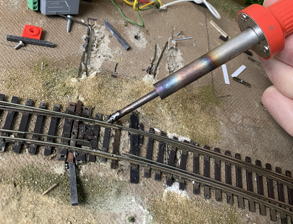
But before restoring the linkages, I needed to do more painting of rails, as I mentioned in the previous post (see first paragraph, above for link), and I did so, completing work on both new switches on the main line to Santa Rosalia. I also added ties where they were missing, using old surplus tie strip or individual wood ties. 

The next step was to restore the more important of the two linkages, the one at right in the photo above, which controls  the Walthers curved switch. That’s because when structures are put back in place, it is behind the storage tanks of my Richfield oil dealer, thus not accessible for manual operation. In the photo below, the new trenches are cut. 

Finally, the linkage was reconnected and the correct motion of the throwbar verified, for the Walthers switch. This may have to suffice for the upcoming op session, unless I find time to fix the scenery surfaces. But at least this part is now working.

It is frustrating to continue to work the same problems in the same area of track. Hopefully this time it will yield a more permanent result. Thanks again to Jim Providenza for his help with a major part of this effort.

Tony Thompson 

Monday, November 17, 2025

Trackwork wars: Part 16

When last we visited this unwelcome topic (unwelcome to me, anyway), I had torn out both of the curved switches in the lead into Santa Rosalia, and Jim Providenza came over to help install a pair of new ones in their place. That was great, but we soon discovered that the first of the Peco switches into town also needed to be replaced. So I tore it out, and some nearby trackage. The state of play at that point is shown on the repeat photo below. The story is at: https://modelingthesp.blogspot.com/2025/09/trackwork-wars-part-15.html . 

My first step was to install a new Peco switch, along with some replacement trackage where a foot or so of the lead to the team track had been removed. The new track is shown below (compare photo above), along with the still-unsoldered feeder wire with the yellow insulation. 

I was about to solder some of the new rail joints, when it occurred to me that continuing work on the switches that were installed earlier might need adjustment of location, so I put off doing that. Then Jim Providenza came over again, with complete toolbox, to see how we could make things move ahead. I really appreciate Jim’s help with trackwork that I’m not as good at as I used to be. He of course brought his Santa Cruz Northern coffee mug. 

Most of the new switches work fine, but there continues to be a dip in the overall track. To see if it could be made better, Jim used pieces of an old Athearn kit box to shim up the track. This surprised me in that it actually did help. Here is how it looked with the cardboard from the box underneath.

This seemed to improve enough of the problems that we called it a day. I went back and soldered the feeders and some more of the track joints, inserted ties where they were missing between sections, and started painting the rail. I still use my long-time choice for this paint, Floquil Roof Brown, as I think it gives the right dark brown commonly seen on rail in the world. Then dirt “ballast” will be added. 

More testing needed, but the track  is coming back into service, and needs to be gotten ready for the next operating session. Hopefully we will have all this trackage back in full service by then!

Tony Thompson 

Sunday, September 21, 2025

Trackwork wars: Part 15

In this long-running series about the combat between me and some of my trackwork, we have looked at several different parts of my layout. But more recent reports have concentrated on the track between my towns of Ballard and Santa Rosalia. The last post described some significant improvements accomplished by the efforts of Jim Providenza (you can read it at: https://modelingthesp.blogspot.com/2024/05/trackwork-wars-part-14.html ). 

After the work described in that post, I could operate even my long-wheelbase Consolidation steam locos over that trackage. But in fact, this only worked at a slow crawl. Any speed increase toward what any experienced operator would choose, and bingo! off the track. That was even true for 4-axle diesel switchers. Jim and I knew that further work would be needed at some point.

Recently, testing this yet again, and still seeing derailments, I set about examining individual rail lengths carefully, and discovered that some were still bent, in ways not easy to correct, both in, and out of the plane of the track. I suppose this may have been done while correcting other faults. But I finally faced up to the fact that this just wasn’t going to get fixed. Here is how the work area looked at that point, with all structures moved out of the way.

Jim and I discussed it, and we agreed that the simplest way forward was simply to buy two new switches to replace the two now in place (a Peco #6 left hand “Unifrog,” and a Walthers curved right-hand 20–24"), and start over. This is, in a way, pretty discouraging, since both he and I had invested a lot of time and effort in the trackage you see above. But a fresh start seemed best. 

I patiently un-soldered all the feeders and whichever rail joiners were soldered, for these two switches, then removed both of them. I also un-linked both switch machines. It was discouraging to be back to this point again, but it seemed like the best option here.

Some long-time readers will be feeling that I have been through this before. Right you are, I already tried replacing those two switches, but ran into a series of problems that rendered that solution less successful that I hoped (the previous saga is at: https://modelingthesp.blogspot.com/2024/04/trackwork-wars-part-12.html ). 

The other day, Jim kindly came over, with complete tool box, and set to work. The need to connect track at both ends of the area (as you see it above) is definitely constraining, and called for a few mods to both of the new switches. Below is Jim, starting the effort, with his coffee mug in the foreground (with a label for his Santa Cruz Northern layout, and its slogan: “50 years of occasional service”). You can click on the image to enlarge it if you wish.

As work progressed, including some modification of both commercial switches to align correctly, the new trackage emerged (shown below not quite all attached). Also revealed, unfortunately, was a problem at far right with a Peco switch that is part of Santa Rosalia.

Close examination and attempts to correct that Peco leading into Santa Rosalia (SR) revealed instead some bent rail and gauge problems. We decided that that one had to go also. Removing it and cleaning up a couple of short track segments, left the area looking like this. SR entry via the lower track in this view is intact, but obviously not the upper track.

For the time being, I can only operate into part of Santa Rosalia, until that entry switch gets replaced. The switch machines need to be re-linked, too. But more important is that the overall track connection between Ballard and SR is re-established, track which also serves as the tail track for Ballard switching. So there is definitely good news, but of course, there remains more to do!

Tony Thompson 

Tuesday, July 2, 2024

Update on switch machine installations

On my layout, nearly all switches are hand-thrown (as would be such switches on a prototype rural branch line like I have modeled). But in a few places around the layout, where manual access is not convenient, I have had to provide an alternative (for more discussion on this subject see: https://modelingthesp.blogspot.com/2019/02/powering-turnouts.html ).

The one place I have powered the switches is where the track runs right behind some industries, making it awkward (and potentially damaging to structures) to hand-throw the switches. But this installation, in the track between my towns of Ballard and Santa Rosalia, has been involved with some trackwork difficulties. 

When the original track switches were in place, I could operate them easily with the MP1 machines, because the throwbars of the switches were not very close together. I described this installation in a previous post (you can see it at: https://modelingthesp.blogspot.com/2024/04/trackwork-wars-part-11.html ). Here is how it looked:

But when I had to replace these two track switches, a variety of track conformation issues caused the throwbars to be located closer together than before. This in turn meant that the MP1 machines would interfere with each other if the two actuating rods were both perpendicular to the track. As a compromise, I located the right-hand MP1 at more of an angle to the track.

This does require a little longer throw, easily accommodated in the MP1 because the throw distance is adjustable. But there was also another effect, greater friction, and sometimes the machine would only throw the switch part way. I was pondering what to do, when the track issues got worse.

The machines had to be disconnected and moved out of the way when the switch-gauge shrinkage issues were being corrected, that is, by restoring the track gauge (see this post: https://modelingthesp.blogspot.com/2024/05/trackwork-wars-part-14.html ). I then decided to try moving the two machines to be more symmetrically oriented to the track. This essentially involved enlarging the throwbar “trenches” somewhat to the left of the existing trench for each machine, preparatory to relocating the machines.

When installed, the two machines now had a nearly perpendicular throw direction, relative to the track axis, which quickly proved to be a much better mechanical arrangement. 

Next, as previously, the tubes over the throw rods (visible above) will be “buried” with paper mache to conceal them. But the important part, at this point, is that both of the two MP1 machines now operate properly, with the  more nearly perpendicular throw angles.

Tony Thompson

Tuesday, May 21, 2024

Trackwork wars, Part 14

Recently it seems like I keep coming back to the same troublesome switches, the two new ones I installed on the main line between Ballard and Santa Rosalia on my Santa Rosalia Branch of the Southern Pacific. Some readers may be tired of the topic; rest assured, so am I. The last time I reported on this area (here’s a link to that post: https://modelingthesp.blogspot.com/2024/04/trackwork-wars-part-12.html ), I thought I was getting close to completing my repairs.

I should have known better. During the ProRail operating sessions last month on my layout, I did find that a steam locomotive with a wheelbase as long as a Consolidation encountered tight gauge in this area, therefore derailed consistently, and accordingly a diesel switcher had to be used for the branch local freight. Even then, tight gauge, and derailments, were still encountered in the new switch. (For a report on the sessions, see this post: https://modelingthesp.blogspot.com/2024/04/prorail-2024.html ).

The problem area is shown below. The tight gauge is present over about one-third of the distance from the throwbar to the frog, outside that it was fine. I should mention again that this was a brand-new Walthers curved switch, which I carefully checked for gauge before installing, and it was fine. What I evidently did during installation to change that, I can’t figure out. But now to fix it.

My first thought was that I had somehow put stress onto the switch during installation, stress transverse to the track, that could have shrunk the gauge. I tried using a hair dryer to get the ties and rail fairly hot and try to broaden the gauge by pulling apart the stock rails in this area. Didn’t work, maybe because I didn’t continue long enough or get the track hot enough.

Even before ProRail, I had discussed this problem with friends Jim Providenza and Paul Weiss, who allowed as how they would lend a hand, after ProRail. Accordingly, Jim came over with his full toolbox of “layout maintenance” materials and tools. He quickly saw that the overall curvature of the track through the two curved turnouts wasn’t uniform. Since he felt that that had to be fixed before we addressed the tight gauge, he cut the outer stock rail of the Walthers switch loose from the ties and re-located it on a correct curve. Here he is at work.

What Jim was doing in the photo above is a technique I hadn’t seen or thought of before. Rather than try and apply spikes through holes drilled in ties, Jim was making a more secure rail attachment, by drilling through the foot of the rail, and then through the tie. Note below the spike head locations. (You can click on the image to enlarge it if you wish.) This is the outer rail of the curve, looking sort of toward the aisle.

With that done, it was time to address the gauge problem. Now the inner stock rail needed to be carefully gauged and likewise spiked through the rail foot to ensure the correct gauge. Finally, I soldered the rail joints where the two curved switches came together, as this had been an area of previous problems. Of course they were carefully gauged first.

You can see above that both of the MP1 switch machines had to be unmounted temporarily to provide plenty of room to work. These will of course be re-mounted to power these two switches.

Now, as I had been doing ever since the problem was even close to being solved, I ran the severe test: one of my  SP Consolidations. The long wheelbase of this locomotive type challenges the trackwork as milder tests do not.

I was so pleased to see this locomotive run smoothly through this track area. Major thanks to Jim, for coming over and lending his expertise and skills, and for seeing the need to adjust the entire track curvature in this area. Now I really hope this is the last report on work in this layout area!

Tony Thompson

Monday, April 15, 2024

Trackwork wars, Part 13

I'm pretty much done with the previous challenges described in this series, but one more interesting one did surface during my last operating session. There’s an old saying, that using a layout inevitably breaks things. Well, this was another demonstration of that adage. (For previous series posts, see for example: https://modelingthesp.blogspot.com/2024/04/trackwork-wars-part-12.html ). I’ll describe the issue because it was not a simple problem.

The interesting aspect of this particular problem is that it involves several different things. First, it’s a really old switch, dating back at least 40 years on the layout. (It’s one of the Russ Simpson “Scale Model Railroad Trackwork” No. 5 switches, wonderful components, and if I had managed to buy more of them, I would have used them throughout the layout. The point rails are all in one piece, from frog to throw bar.) 

Second point, I had had problems years ago with electrical performance of this particular switch, which relies on the contact between point rails and stock rails. I had solved this many years ago, by adding the contacts of a micro-switch under the layout with an operating wire up through the layout and into the hole in the center of the throw bar. Movement of the points moves the wire, which moves the contacts to the appropriate connection.

In the photo below, the switch point rails can be seen to be joined by a brass strip, to which they are soldered. In the center is a rivet which attached the brass strip to a plastic throw bar underneath everything. Or there was. It broke at the rivet, and the two pieces are lying parallel to the track, just above the points. The throw bar in turn has a hole at one end (at left in the view below), which was the connection to the (un-mounted) Bitter Creek ground throw which is at upper photo center.

My first shot at fixing this was to try and glue the left half of the throw bar (as you see it above, at left), back into place under the brass connector strip. This worked, but didn’t survive many throws. It was clear I needed to make an entire new throw bar.

I chose some Evergreen scale 6 x 10-inch styrene strip, and cut a length equal to the original throw bar. I then rounded the corners and drilled two holes, about no. 55, one in the center (to accommodate the wire activating the micro-switch contacts below the layout) and one near the end, for the ground throw. And I painted it black.

It wasn’t easy to slip the new throw bar under the switch points and over the center wire, but I got that done. There was a slight bend in the frame of the Bitter Creek throw, so I temporarily replaced it with a Caboose Industries throw, just to get it back in service.

This works well enough, and for now will remain this way. I was glad to be able to keep the successful electrical arrangement on this switch, while replacing the throw rod. The test will come, of course, when visitors operate through this switch, as they will repeatedly for almost any switching task at Shumala. Fingers crossed.

Tony Thompson

Saturday, April 6, 2024

Trackwork Wars, Part 12

My efforts to correct a pair of troublesome switches near the outer end of my Santa Rosalia Branch layout are continuing. In the previous post on this topic, I showed the beginnings of replacement, after the offending switches had been removed and discarded. (That post can be viewed at this link: https://modelingthesp.blogspot.com/2024/04/trackwork-wars-part-11.html .) An important issue unresolved at the end of that post was the realignment of the MP1 switch machines that power these two switches.

The decision I made was to move both MP1s, but not very far. This can be best illustrated with an overhead photo, showing an intermediate step. In the photo below, the MP1 at left has been shifted leftwards, and the trench for its operating rod enlarged to the left. That permitted the MP1 at right to be moved leftwards also, and on the premise that it will operate all right at an angle to the track’s perpendicular, a new trench was cut. The old trench is the empty one at the right.

Next came fitting the curved switch that goes to the right of the photo above. This had complications, since it was too long at the throwbar end, and too short at the far end. I fixed the latter with a couple of short segments of rail (a few millimeters long), soldered into long rail joiners.

I then proceeded to fit the track together. Though this was a little demanding, given that the area I was working in is among the least conveniently accessible on the layout, I did get everything lined up and assembled. Here you see it all, prior of course to detailed testing of the work and verification that it would operate okay. Both MP1 switch machines are connected too.

I began testing with a long-wheelbase Consolidation steam locomotive, just to see what is likely to be the worst case. Loco SP 2829 worked fairly well over this new track, but inconsistently seemed to find areas of less than perfect gauge. I have continued work to try and find (and correct) these little bugs, and have steadily found and fixed a number, but am sure more needs to be done.

So it’s clear that this new pair of switches is not exactly ready for “prime time,” as we say, but probably will be all right for my upcoming operating session. To be safe, I’ll probably use a 4-axle diesel switcher on the local, just to give a little margin for remaining problems.

Tony Thompson

Wednesday, April 3, 2024

Trackwork wars, Part 11

When last we visited this topic, the subject was the need to replace a pair of switches on my layout that had caused derailments and other trouble many times, over numerous operating sessions. Sometimes severely, sometimes not, but definitely trouble. I showed the location after removal of one of the switches (see that post at: https://modelingthesp.blogspot.com/2024/03/trackwork-wars-part-10.html ). 

I next completed removal of the two switches by taking out the curved one at the right of the photos I have been showing in prior posts. Here is the area with both of the offenders removed. At the top of the photo below is the new Walthers curved switch that will be installed.

After some careful fitting, a replacement No. 6 switch was placed at the left of the scene shown above. Rails were painted a kind of “Roof Brown” color, and aligned with the trackage at upper left (two tracks: one is the lead to the Jupiter Pump & Compressor plant, the other is the main track in Ballard). Testing of the new switch seemed to work well, though of course locomotives could only be run onto the new switch at this point, not completely through it and beyond. Here I was checking level.

With an operating session coming up, it occurred to me to carefully test other switches on the layout which have been problematic in the past. Almost immediately I found that one of the point rails at the east end of the Ballard double main had come un-soldered. This happened once before during an operating session, so I was glad to find it now, and re-solder. Here is how it looked when it had just failed.

My next project was to fit the second replacement switch into the area being worked. As I was starting this, I realized what a  different scene was being created by the work tools and materials, compared to the layout scene that usually exists here.

The new switch was readily fitted into the existing track alignment, but a new problem arose: the throw bar on this switch is located differently that was the case for the previous switch, and not even close — instead, it’s around three-fourths of an inch away. And what’s worse, it’s different in the direction that is closer to the adjoining switch, meaning the two MP1 switch machines can’t remain in their present locations.

I’ve shown all this below, with a large red arrow aligned with the current location of the throw bar of the switch that was previously located to the right. You can readily see, not only that this location isn’t at all close to the throw bar of the new switch, but equally seriously, that the new bar location would practically touch the switch machine to the left.

Obviously, I have to dig up the actuating rod that is buried at right, as it no longer connects to anything. One possibility then is to simply rotate the machine at right somewhat clockwise, and then operate a connecting rod at an angle to the track, instead of perpendicular.  It might also be practical to move or rotate the MP1 at left. Rotating it 180 degrees would probably be easiest. Then the one at right could be relocated so as to operate perpendicular to the track. Moving both switch machines isn’t attractive but might prove necessary. More on all this later, when progress has been made.

Tony Thompson

Thursday, March 28, 2024

Trackwork wars, Part 10

In a recent post, number 9 in my series on this topic, I showed the work done in leveling some track in the area between my layout towns of Ballard and Santa Rosalia (you can read that post at this link: https://modelingthesp.blogspot.com/2024/02/trackwork-wars-part-9.html ). 

But even as that work was being completed, I realized it was not all of the problem. There remains some variability in the track gauge that still can cause derailments, and in a few places the track gauge becomes too tight. Thus this post.

For example, I have used the clear plastic “test car” shown in the previous post (see first paragraph for link), and even with the track leveled, there are still derailment problems. Below you can just see the leading wheel lifting and turning to derail.

Both these switches have given trouble for some time. The one at left in the photo below is a Peco, and like other Peco switches I have, it has evidently experienced shrinkage in its plastic parts, and the track gauge is now too tight. I corrected this once before, by filing the inside of the rail head. By now I’m not too enthused about continuing with that, as I have had to do the same with two other Peco switches on the layout, and it’s an apparently endless task. At least the other two don’t cause derailments after their gauge is corrected.

[By the way, I contacted the Peco “help” service about this shrinkage. Amazing how naive I was, even at my age: I thought they might apologize for the defect, might even send me a replacement. But in fact, Peco replied that they “had never heard of anyone experiencing shrinkage in a Peco switch,” though I have three different Pecos that have done this, and others around the U.S. have told me the same. Makes me take a deep breath before purchasing more Peco switches.]

Next I began to measure the individual rails in the two switches, since some appeared to perhaps be bent. I soon found that indeed there were bent rails, bent vertically, not horizontally, which is less convenient to fix (perhaps the result of an earlier derailment). At first I began to try and straighten them, which wasn’t going well, when it came to me: “What am I doing? Replace the bloody things!”

My first step, in which I admit I took pleasure, was to remove the annoying Peco switch. Once it was separated from the other track, I felt better already.

Over at the right edge, you can see the existing curved switch, and just above it, a new switch, one I had in stock, but not one that would fit.

I spent some time shopping for new switches, and reading a couple of email lists for comments about the various switches on the market. For the curved turnout at the right of these photos of the area (see middle photo, above), it looked like the dimensions of the relatively new Walthers line of “DCC friendly” switches would fit. 

For the other switch, a left-hand #6, I am still looking at options. The Walthers switch of this kind has a very straight diverging route beyond the frog, which I don’t think will work in my location. There are a couple of other manufacturers of switches that are options.

It would have been nice if these new switches could be located with throw bars exactly where their predecessors were located. But I realize that isn’t likely, so probably the entire switch machine locations (see photo above) will have to be moved, including digging up the buried tubes that carry the activating wires. That’s just to be expected as part of the project.

Now I just need to get the new switches in house and start restoration. Progress reports later.

Tony Thompson

Thursday, February 1, 2024

Trackwork wars, Part 9

From time to time, I document some of the maintenance and upgrade work done on my layout. The most elusive solutions and most persistent problems seem to be trackwork and electrical ones, thus the names of a series of posts about each, under the “wars” title. The “electrical” series is the longer, but as the present post demonstrates, I have my share of trackwork problems too. 

The previous post in this series,though not a logical predecessor as it was in an entirely different part of the layout, did focus on track leveling issues (see that post at: https://modelingthesp.blogspot.com/2023/12/trackwork-wars-part-8.html ). That was very much an issue in the area to be discussed in the present post, which is shown below.

This is the area where the layout transitions from the town of Ballard, to the left of the creek, to Santa Rosalia, at the right of the creek. It has been troublesome for some locomotives in several previous operating sessions, but recently has become worse. 

The building with the gray roof, against the backdrop, is the site for the MP1 switch machines powering the adjacent switches. (For a discussion of the MP1 machine, see: https://modelingthesp.blogspot.com/2019/02/powering-turnouts.html ). With that building removed, the MP1’s are visible (below). I’ve been pleased with these linear-motion switch machines, following their installation (see: https://modelingthesp.blogspot.com/2023/03/powering-few-more-switches-part-2.html ). It was essential to use surface-mounted switch machines in this area because there is trackage right under it.

Note in the above photo the small level on the track at left. I quickly discovered considerable variations in track level over short distances, an excellent arrangement to cause derailments. Even this simple tool can easily reveal the level differences that are causing trouble, as you see below. The area depicted in both photos is a close-up of the area shown above, one photo for each switch.

This sharp difference in level over a short distance has to be corrected. I used white styrene (HO scale 1 x 10-inch strip) to cut shims, and try them out under the track to get closer to cross-level throughout. Below is a first cut at these corrections. They are not final, but closer to what is needed.

The next step was to try and use the transparent “test car” to check consistency in the track leveling. One attempt is shown below. But this is not a very effective test, because the truck mounting is not very stable against tilting. One can carefully level the car, and try to gently move it over the track to be tested; but even the slightest of bumps will change the tilt of the car. Something better was needed.

My next test was to bring one of my steam locomotives to the area, and slowly and rapidly back through and then go forward through, the affected area. After all, this is the real goal of the track project, to avoid derailments. This is shown below. Note that the trackage being tested is all unballasted, which won’t change until the track problems are at least close to “fixed.”

Much of the previous problem, and at the usual derailment location, was remedied. But one position of the switch to the right in the above photo still gave some derailments. So further work is needed beyond the leveling that was described above. I will return to this problem.

The work so far seemed successful, though more is needed, and more thorough testing. Of course, the real test, as any layout owner knows, is an operating session with visitors, ideally ones you want to  impress; but that will have to wait. Right now, things are certainly improved, though I need to continue to experiment, modify, and of course, test and test . . .

Tony Thompson

Sunday, December 24, 2023

Trackwork wars, Part 8

Over the years, my maintenance issues with my layout have involved many things, but the two most frustrating have been electrical (spawning the name “electrical wars” for posts about them), and to a much lesser extent, trackwork (thus the obvious counterpart, “trackwork wars”). This is another of the latter topics, interestingly in about the same area as the previous such post (see it at: https://modelingthesp.blogspot.com/2023/10/trackwork-wars-part-7.html ) but a different issue.

Below you see the obvious dip in the track in the area of the entrance switch into my layout area of East Shumala. This was discovered by the usual method, derailments during an operating session (for a description of the session, not the problem, see: https://modelingthesp.blogspot.com/2023/12/december-operating-session.html ). I amused some of the visiting operators, when this dip was discovered, by exclaiming “It’s a new dip!” But I was correct; this wasn’t evident six months ago.

But in fact the problem is not only at this location. Moving to the right of the above photo, it was evident that though the main line through Shumala is level, the switch diverging toward East Shumala from the main line is downhill over a longer area that suggested in the photo above. So a wider area needed to be corrected.

I have a way of correcting dips, as I showed in the previous post (link in the first paragraph at the top of this post). I force a putty knife into the track support (installed too long ago to be sure, but I suspect Homasote) under the area that needs to be raised. This is near but not the same place as the area I corrected in that previous post (top of post).

With an opening created, I slide in some pieces of Evergreen styrene strip, 0.040 x 0.125 inches (HO scale 4 x 12), about an inch long, into the opening where the putty knife was.

As you see above, these were a little too long, and the protruding ends were cut off. Then a check with my steel ruler showed that there was no longer a dip in the track. In the photo below, the rail joint is at the 10-3/4-inch mark on the ruler, and there is no discernible dip any longer. And the mainline track is also raised to be level, correcting what is shown in the second photo from the top of this post.

The very ends of the styrene strips are evident above, but these will be covered with ballast in my upcoming tour of the layout to correct innumerable areas where scenic ground cover needs to be added or renewed.

With this track corrections, repeated switching moves revealed no derailments (of course, as every layout owner knows, bringing in guests may reveal a different result). I realize that this and other track subsidence problems probably indicate that my sub-roadbed or track boards may have shrunk, warped or shifted in some way, but rather than tear up the layout down to the framing to fix things from the bottom up, I will continue to make these kinds of “corrections” to the track.

Tony Thompson