Showing posts with label Techniques. Show all posts

Thursday, June 25, 2026

Waybills, Part 131: model bill production

A recent inquiry made me realize that my ongoing method of producing waybills has never really been presented in its current form, though one could infer it from earlier published articles as well as posts in this blog. In the description below, Rather than cite previous relevant writings, I’ll present as full an account as I can.

First of all, the waybill format I adopted more than 15 years ago, closely adapted from the AAR standard waybill form, cut down for model use. It is a 2.5 x 3.5-inch format, chosen to fit into a baseball-card-collector clear plastic sleeve. The sleeves are evidently produced in large volume, and are quite cheap from on-line vendors, barely a penny each. A blank waybill looks like this: 

These blank waybills are Photoshop tiffs, and are filled out with the type tool in that application. I have made them in 1200-dpi bitmap mode for sharpness. Then to print them, I have created an InDesign template (though any layout app would work) for 8.5 x 11-inch paper, with guidelines for placing waybill images on the page (the light vertical and horizontal lines), and heavier cutting guides (only at top). At top center there is also a place to note the date printed.


When all nine cells on the template are filled with waybill images, and the light guide lines removed, a page ready to print looks like this. Cutting guides at top remain. These happen to be waybills for perishables, so will use the AAR-recommended pink stock. I noted this along with the printing date at the top.

When these are printed, I cut them with a rolling paper cutter (mine is an old Rodahle 51200) for clean cuts and safe handling. Each will then be paired with its appropriate Empty Car Bill (yellow, as were many prototype ones) in the plastic sleeve. I got the idea of the sleeves from the late Bill Neale’s article in the February2009 Model Railroader

This description should update what has been presented in past years, and clarify my process. If any part of it isn’t clear, please feel free to ask further.

Tony Thompson 

Wednesday, August 13, 2025

Freight car kitbash, Part 2

In the preceding post, I showed the prototype for my modeling goal, building a 50-foot automobile car with a Viking roof (because I had a nice molding for that roof). I also showed the Branchline post-war 50-foot box car model that I chose as a basis, then stripping the factory paint and adding steel nuts for weight and installing the doors to stiffen the body. The post is at: https://modelingthesp.blogspot.com/2025/06/a-simple-freight-car-kitbash.html .  

An immediate problem with the Cannonball Car Shops(CCS) ends is that they are too tall. If you measure a typical HO box car of 10-foot inside height, the exterior height of the end, beneath the roof, is about 9 scale feet. Post-war cars, usually 10' 6" inside height, are more like 10 scale feet end height. But the CCS ends are 11.5 scale feet high. Certainly not clear what they were intended to model, but I recall fighting with the height of the Red Ball white metal versions of the same end as a teenager.

Since the CCS ends are styrene, one possible solution is to “scribe and snap” to remove one rib of the end, which removes close to one scale foot of the height, then re-assemble when attaching the end to the car. With the first cuts made, here is what you have — of course the cuts need to be cleaned up and the joints fitted to match, and the coupler box frame at bottom removed. Original end at left.

This method, however, turns out to remove more than I wanted, so I had to file down the narrow “middle” piece quite a bit for the end to fit.So I decided to try something different on the other end, simply removing the desired amount only at the top of the end. This works more simply, but helps reveal that the ribs on the end are a little bit too big. Anyhow, here is that modified end, attached to the car body. 

This size issue reminds me of a belief of Richard Hendrickson’s, that early HO scale manufacturers were not sure the HO would win out over OO scale, so made parts that were intermediate in size, between the two or sometimes just a little oversize for HO, such as the earliest Silver Streak kits, which have this oversize character. Maybe the early Red Ball parts were also intended for OO scale, or to lie in between the two scales. But I have made the ends fit.

Next I simply added the kit detail parts to the body. With a model like this, with ends not intended for use with the kit, I like to begin with the ladders. Side ladders are fitted as the kit intended, then the end ladders can be added so that the rungs align with the side ladders (a prototype requirement). In the illustration below, a replaced rung is oversize; it was replaced with smaller styrene rod.

Continuing with the body details for the project at this point just involved following kit instructions, so I won’t go into that. I will continue with other parts of the project in a future post.

Tony Thompson 

Wednesday, May 7, 2025

A few comments on chalk marks

Most modelers of freight casrs from earlier times are ware of the chalk marks that could be found on car sides. For the most part, these were switchmen’s marks and were not, nor should they be referred to as, graffiti. A photo I have shown several times, taken at Englewood Yard on the T&NO, depicts a yard clerk applying such a mark.

In the photo, he is writing with what is still known as “railroad chalk,” roughly an inch in diameter. White and yellow were widely used, but other colors, including blue, were available. Below I show a couple of sticks of this chalk. It is quite sturdy and unlike blackboard chalk, not easily broken. And the large diameter means that chalk marks made with this chalk were relatively broad, not like what we associate with blackboard chalk.

I have written about this topic in two previous posts, one from way back in 2011 (see it at: https://modelingthesp.blogspot.com/2011/11/chalk-marks-and-route-cards.html ).  The second one was a couple of years later and included a number of model photos with chalk marks applied. That post is here: https://modelingthesp.blogspot.com/2013/04/more-on-chalk-marks.html .

Since many if not most prototype freight car photos do show at least a few chalk marks, we need to include them on our models. For years, there have been commercial offerings, both dry transfers (Clover House) and decals (Sunshine, Champ, Speedwitch Media and others), and these may meet your needs. But it is simple to write them yourself. A sharp artist’s pencil in white, gray or other color makes this simple.

But then comes the issue of what to write. You can just make something up, or a better option is consulting good, clear prototype photos, such as the photos in the superb series of books prepared by Ted Culotta, entitled Focus on Freight Cars (Speedwitch Media); Volumes 4, 5, 7 and 9 remain available (go to: https://speedwitchmedia.com/ ). Here’s one example, taken from the series Vol. 4, page 82. The car shown is SP 38017, part of SP Class B-50-19, a 1937 AAR box car.

Note that the message being conveyed is by no means evident, but swirls or slashes of chalk like this, and one or more numbers like this “17,” are very common in prototype photos. Note also two previous messages that are lined out, presumably superseded. Sometimes writing is fairly large, as in this photo of CCC&StL (NYC) 58392, from page 17 of Volume 4; this would be easy to imitate.

And as mentioned, it is quite common to find older chalk markings lined out, crossed out, or X-ed out. That’s well shown in this example from Volume 1, page 61, showing one end of SP 29889, a member of SP Class B-50-14. It was common for the chalk marks to be concentrated at either end of the car side, as you see here.


And sometimes it’s just a squiggle, maybe the clerk warming up his wrist, as in this photo of Seaboard 18735 from Volume 4, page 48. This was one of Seaboard’s 1932 ARA box cars. That’s a defect card holder right above the chalk mark.

All these prototype examples should provide lots of ideas about “what to write” when adding chalk marks to a model. As a single model example, below is a gondola on which I used a blue pencil (the classic editor’s “sky blue” pencil). This is an Ertl model I have posted about (see this link: https://modelingthesp.blogspot.com/2024/10/small-project-maine-central-gondola.html ).

Tony Thompson

Friday, January 17, 2025

Yet another Tony Koester book

I recently received a question about my book reviews, asking why I hadn’t reviewed Tony Koester’s 2019 Kalmbach book, Time-Saving Techniques for Building Model Railroads. I do own the book, and have enjoyed browsing in it, but probably because my own layout is already built, and fairly complete at this point, I didn’t feel an impulse to review it. But here goes. 

Tony K. has always advocated a number of specific approaches for layout building, and this book pulls a number of them together. I enjoyed seeing Doug Tagsold on the cover, renowned among operating people for his rapid and impressive layout building. He’s shown in the early days of at least his third (and present) layout.

The book, as was usual with Kalmbach Media books, is 8.5 x 11 inches in size, softbound, with 112 pages. As with all of Tony’s books, it is handsomely illustrated with informative photos.

The scope of the book is well demonstrated by names of the chapters. Here is the Contents page:

An interesting and certainly simplified approach to upper decks on double-deck layouts is to use shelving systems. Koester himself has done this, as you see below. Note that the steel brackets for the upper level are already painted sky blue. The backdrop will be notched to fit around them.

One interesting time-saving method described for a couple of layout is foam-base scenery. You see that in the book cover photo, at top. Here is another view of Doug Tagsold’s 1:72 layout, showing at left the fairly complete scenery contours accomplished with foam, and at right the scene when the usual materials are added.

Another person who has used this approach is Bill Darnaby. He has emphasized narrow track boards, and likes the flexibility of the foam (easily modified). At top is the 2-inch blue foam that is the foundation, being applied to wall brackets. Next below is trackwork being placed atop the foam, with easily-added ditches alongside, and at bottom we see a completed area.

I like this book, and have enjoyed reading and re-reading it. If I had to offer a criticism, it might be that there are too many photos of a finished layout (the author’s) and not enough in-progress views or views of more and different layouts. But it’s not a “step-by-step” book, it’s an idea book, and the points made about time-saving approaches are quite valid and clearly presented. That’s why I believe the book does what it was intended to do.

Tony Thompson


Saturday, November 30, 2024

More about making crate and box loads

I have written about this topic before, and in the present post, am adding more examples, in part to show a different technique. Crated loads on flat cars and in gondolas are prototypical and relatively simple to make, and offer variety in what your open-top cars carry. I showed a variety of crate and box types in my first post on the topic, some years back (see it at: https://modelingthesp.blogspot.com/2012/03/open-car-loads-crates-and-machinery.html ). 

I expanded my ideas on this topic a bunch of years later, and treated it as a “Part 2” of the same topic, helpful in finding the predecessor, as it’s linked therein: https://modelingthesp.blogspot.com/2021/05/open-car-loads-crates-part-2.html . This post was about building some large crates as hollow styrene boxes, and the project completion was described later: https://modelingthesp.blogspot.com/2021/06/open-car-loads-crates-part-3.html .

The present post is about still another approach. I recently came across some hardwood offcuts from a project, and immediately thought of crates, but they were not square all around. On each one, the cut on one side was not square to one other pair of sides. But these could easily be braced to level them in use. I began by painting them light gray, then carefully examining them for any places that needed a little modeling putty, often lines of wood grain. I used Tamiya putty for this.

With the putty well dried and sanded smooth, another coat of paint made the boxes ready for use. Next came leveling them. Using a small square, as shown below, enabled me to identify exactly what size of stripwood or styrene to use as a level on each block.

Each wood block was different in what it needed. But the important part is that the styrene piece need not exactly fit at the extreme end, but could be placed  at an intermediate point, sufficing to level the block. An example is shown below.

With each block leveled in the way just described, I then added outside trim to hide the angle. For the block shown above, I used styrene HO scale 1 x 10-inch strip. The bottom of the block is shown below. When upright, of course, this is hidden.

I then painted the trim to match the block. Next came a choice of label or emblem on the load. Many shippers added a prominent name or logo on shipments like these, and this makes the load interesting too. One can of course browse the internet for emblems of famous companies; this is what I once did in making an emblem for an appliance carton (see: https://modelingthesp.blogspot.com/2017/10/cardboard-cartons-part-2.html ), using General Electric. For the present project, I decided to use mining equipment, and where better to look than the ads in journals for that industry, like these:

Next came scanning of appropriate ads, reduction to a useful size for HO loads, and printing out on a high-resolution color printer at my local copy shop. Then the paper labels can be glued to crates or boxes with canopy glue.

It may be noted that the labels are added on the upper part of the crate. This is a deliberate choice so that they are visible when used as gondola loads as well as when they are flat car loads: see below. (You can click to enlarge.)

It might be asked, “Why mining loads? There’s no mine on that layout.” That’s true, but there was mining in the vicinity, as I’ve explored previously (see my post at: https://modelingthesp.blogspot.com/2016/10/modeling-mining-in-your-locale.html ). These crates can be destined to my off-layout mining company, Monarch Mining, which produces chromite ore. I have written a bit about this company and the ore (the post is here: https://modelingthesp.blogspot.com/2016/10/modeling-mining-part-2.html ).

With the completion of these loads, I have some additional crates to add to my freight car operations. Now to make some suitable waybills for the movement of these products . . .

Tony Thompson
Monday, September 23, 2024

The Hendrickson USRA box car, Conclusion

This project is essentially the completion of a freight car build begun by Richard Hendrickson and inherited by me. Doubtless I would have taken up the project long since, but the box in which the partly completed model was stored was located among a group of parts boxes. When I happened onto it, it went right to the workbench.

The prototype is one of the USRA (United States Railroad Administration) box cars acquired by the Georgia Railroad and upgraded around 1940 with new steel side sheathing to replace the deteriorated original wood sheathing. More of the background, and prototype photos are in the first post on this topic (the post is here: https://modelingthesp.blogspot.com/2024/07/another-hendrickson-project.html ).

Richard’s model is essentially a Tichy kit, and he had assembled the body, reworked the roof, and begun underbody work. I completed the underbody and managed the installation of numerous other details, some of them, such as the brass grab irons, which he had selected for the model. That work was described earlier (see: https://modelingthesp.blogspot.com/2024/09/the-hendrickson-usra-box-car-part-2.html ).

One detail installation that may be worth describing is the corner grab irons on the lateral running boards. The kit supplied the Tichy wire grab for this location, but nothing for the support at the included corner, where on the prototype an attachment is present. Modelers often model this with a wire lift ring, actually intended for diesel locomotives. But such rings are badly oversize for house cars. Just for comparison, here is a prototype view (SP Class B-50-18, AC&F photo, used with permission):

This really looks far different than those diesel lift rings. What I have done instead is to glue an over-long piece of wire of the same diameter into the corner hole of the lateral running board, as you see below. Then I can trim it to length to match up with the corner grab when I install it. Note that the end supports underneath the end of the running board are not yet installed.

Detail part installation was completed with a Kadee Ajax brake wheel instead of the Tichy one, and I made the diagonal braces under brake step and running board end from scale 1 x 2-inch styrene. Then I could paint the model. I used Tamiya “Fine Surface Primer (Oxide Red)” because I know it gives an excellent finish, semi-gloss and very suitable for decals. And the color to my eye is a mid-range boxcar red.

The Tichy decals for this car were in the kit box, so I merely had to apply them. The lettering scheme does require a bunch of individual decal pieces between the diagonal braces and the posts, but this is merely tedious. I will show the as-lettered car below. For a prototype comparison, see the car photo in the first post in this series, link provided in second paragraph from top of the present post.

Next I needed to apply trucks (to replace the Tichy “work supports” shown above). In the kit box were Richard’s choice for the USRA trucks retained by Georgia on these cars, Accurail. I added Reboxx wheelsets. Finally, Kadee #158 couplers were installed. Here is the car at this point.

Finally, in line with my usual practice, the car needed to be be finished by adding weathering, using my technique with washes made from acrylic tube paint (see “Reference pages” at top right of this post). To the wash effects, I added a bit extra with  Pan Pastels, then oversprayed with a coat of flat. A few chalk marks and some route cards came last.

That these were durable cars is shown by the 1953 Official Railway Equipment Register, showing 293 cars, all in the rebuilt number series, 34 years after they were built. I am pleased to have one in my fleet, and pleased to have completed another of Richard’s last projects.

Tony Thompson

Friday, August 30, 2024

An Athearn “Blue Box” tank car, Part 3

 This series of blog posts is about using many of the parts of an Athearn “Blue Box” tank car, with the insulated tank body, as the starting point to represent a particular prototype tank car, a Shell Chemical Company high-pressure car I showed in the previous post in the series (see it at: https://modelingthesp.blogspot.com/2024/07/an-athearn-blue-box-tank-car-part-2.html ).

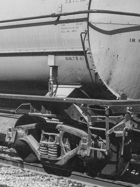
At the end of the previous post (just cited), I had prepared the Athearn bottom sheet part for addition of the turnbuckle hold-down of the tank bands on the car. Below is a repeat of the close-up prototype photo from the previous post (link shown above). You can see that part shielding the emergence of the tank band from under the jacket is right at the longitudinal joint in the jacket.

My intention was to make the cover shield parts, then add turnbuckles. For the cover shields, I began with an Evergreen styrene scale 8 x 8-inch strip, and drilled a #75 hole through it near the end. I then carefully cut off the approximate cube containing the hole, from the end of the strip, and in turn carefully cut the cube at a 45-degree angle. A couple of these parts are shown below. Any parts that don’t come out properly are readily replaced with better ones.

Next these parts were glued to the bottom sheet, right at its top edge (see prototype photo for location), and aligned with the bolster position, as molded into the bottom sheet. 

These are now ready for turnbuckles. The Tichy parts, no. 8021, are cored for 0.0126 wire, meaning that 0.012-inch wire will fit nicely. These need only be short lengths. I cut the wire pieces over-length, glued them into one end of the turnbuckle with canopy glue, then cut the wires to the correct length and glued the wire into the shield pieces,again with canopy glue. I did this with the bottom sheet inverted, as you see below, so that the wire ends were inserted vertically.

The bottom sheet modeling work is now completed, and as soon as work on the upper tank is finished, the two parts can be painted together. I’ll describe all that in a future post.

Tony Thompson

Tuesday, May 21, 2024

Trackwork wars, Part 14

Recently it seems like I keep coming back to the same troublesome switches, the two new ones I installed on the main line between Ballard and Santa Rosalia on my Santa Rosalia Branch of the Southern Pacific. Some readers may be tired of the topic; rest assured, so am I. The last time I reported on this area (here’s a link to that post: https://modelingthesp.blogspot.com/2024/04/trackwork-wars-part-12.html ), I thought I was getting close to completing my repairs.

I should have known better. During the ProRail operating sessions last month on my layout, I did find that a steam locomotive with a wheelbase as long as a Consolidation encountered tight gauge in this area, therefore derailed consistently, and accordingly a diesel switcher had to be used for the branch local freight. Even then, tight gauge, and derailments, were still encountered in the new switch. (For a report on the sessions, see this post: https://modelingthesp.blogspot.com/2024/04/prorail-2024.html ).

The problem area is shown below. The tight gauge is present over about one-third of the distance from the throwbar to the frog, outside that it was fine. I should mention again that this was a brand-new Walthers curved switch, which I carefully checked for gauge before installing, and it was fine. What I evidently did during installation to change that, I can’t figure out. But now to fix it.

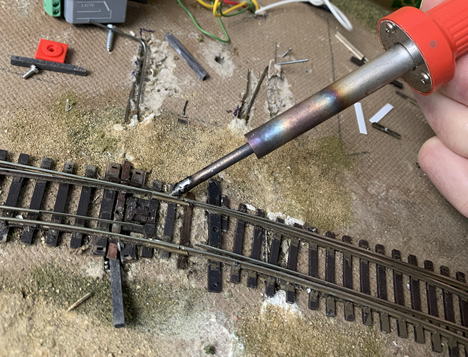
My first thought was that I had somehow put stress onto the switch during installation, stress transverse to the track, that could have shrunk the gauge. I tried using a hair dryer to get the ties and rail fairly hot and try to broaden the gauge by pulling apart the stock rails in this area. Didn’t work, maybe because I didn’t continue long enough or get the track hot enough.

Even before ProRail, I had discussed this problem with friends Jim Providenza and Paul Weiss, who allowed as how they would lend a hand, after ProRail. Accordingly, Jim came over with his full toolbox of “layout maintenance” materials and tools. He quickly saw that the overall curvature of the track through the two curved turnouts wasn’t uniform. Since he felt that that had to be fixed before we addressed the tight gauge, he cut the outer stock rail of the Walthers switch loose from the ties and re-located it on a correct curve. Here he is at work.

What Jim was doing in the photo above is a technique I hadn’t seen or thought of before. Rather than try and apply spikes through holes drilled in ties, Jim was making a more secure rail attachment, by drilling through the foot of the rail, and then through the tie. Note below the spike head locations. (You can click on the image to enlarge it if you wish.) This is the outer rail of the curve, looking sort of toward the aisle.

With that done, it was time to address the gauge problem. Now the inner stock rail needed to be carefully gauged and likewise spiked through the rail foot to ensure the correct gauge. Finally, I soldered the rail joints where the two curved switches came together, as this had been an area of previous problems. Of course they were carefully gauged first.

You can see above that both of the MP1 switch machines had to be unmounted temporarily to provide plenty of room to work. These will of course be re-mounted to power these two switches.

Now, as I had been doing ever since the problem was even close to being solved, I ran the severe test: one of my  SP Consolidations. The long wheelbase of this locomotive type challenges the trackwork as milder tests do not.

I was so pleased to see this locomotive run smoothly through this track area. Major thanks to Jim, for coming over and lending his expertise and skills, and for seeing the need to adjust the entire track curvature in this area. Now I really hope this is the last report on work in this layout area!

Tony Thompson

Thursday, August 17, 2023

Figures, Part 10

 By figures, of course, I mean HO scale people, not columns of numbers. I’ve obviously written nine previous posts about this general topic; probably the easiest way to find them is to use “Figures” in the search box at right. For today’s post, my Part 2 (at: https://modelingthesp.blogspot.com/2017/05/figures-part-2-modifications.html ), would be the most relevant one. It’s about adding an invisible (or very low visibility) base to figures.

Do you have a few figures like the ones below? The two track workers are from a Merten set, no. 870, but I don’t remember the source of the center figure, with the transparent but very thick base. I really don’t want figures like this on the layout; so few people in the real world stand on little discs. And obviously the center figure is very poorly rendered, but can serve on the layout if well away from the aisle.

The first step is to remove these bases. I use a small side cutter, and simply clip next to the feet around the entire figure. Here’s a first cut:

The disadvantage of these gray bases is that they are part of the figure, so clipping away the base leaves that additional thickness at the bottom of the feet. At one time, I extremely carefully removed that added thickness. But in fact, if painted black to match the shoes, it becomes invisible on a base, so I no longer worry about that thickness. You can see it below, unpainted.

For the figure with the transparent base shown above, the base is a separate part, glued to the feet, and usually can be sliced off easily.

I use clear styrene sheet from Evergreen, of 0.010-inch thickness, for bases for figures like these. I just cut a square or rectangle big enough to accommodate each figure’s width and stance. Exact dimensions not at all critical, as long as the base is big enough.

Next comes attaching the bases. I use a dab of canopy glue on each foot, then stand up the figure on its clear base with a steel block for support. Then let dry for a hour or so. In the photo below, you can see the white of the recently applied glue. The glue will dry clear, and is surprisingly strong.

The figures shown above were only part of a larger project to ready additional figures for use on the layout. Below I show several of them together, with a photo angle intended to make the clear base visible, though of course in use the opposite visibility is intended. (The man holding the box at right is from the excellent series of figures from June’s Small World, of Edmonds, WA.)

Another couple of points to recognize: first, clothing for men is fairly ageless, but for women, visible aspects such as skirt length need to fit your era. Second, plenty of figures that may be included in an otherwise-useful set that don’t seem to have any use on your layout. Sometimes you can make changes. Both are touched on in discussing the photo below.  

Notice how different the skirt lengths are on the two women. They do look like women of quite different ages, so the different lengths may be okay; but the shorter skirt, about knee length, was probably not very common in 1953. I will place her farther back in the layout. 

Second, the two men apparently are holding shovels (of quite different and perhaps odd shapes). I don’t have extensive need for gentlemen shovel-wielders, but both can be re-purposed by painting the apparent shovels as brooms. I used Tamiya “Desert Yellow” (XF-59) for this. And both of these somewhat clunky figures will be farther from the aisle.

These procedures can be used for a wide variety of figures, and most importantly for me, has successfully minimized the size and visibility of bases for figures. I don’t like to glue them in place on the layout, but instead can and do move figures around from time to time, so scenes don’t remain static.

Tony Thompson

Wednesday, May 3, 2023

PCR-NMRA 2023

This past week, the Pacific Coast Region (PCR) of NMRA held its annual convention, this time in Sacramento under the auspices of Sierra Division. As I almost always do, I attended the meeting and quite enjoyed the experience. 

I report on meetings like this not because of their intrinsic importance, or because it matters that I was there, but because I hope to encourage modelers who don’t typically attend such conventions to give them a try. I have always found NMRA regional conventions to really be fun.

For me, the primary attraction at such a meeting often is the clinics, where remarkable degrees of expertise in many, many areas of our complex hobby are on offer. This convention was no exception. I show below just one example, Mike Roque during his fine talk diving deeply into the prototype, “Signals: Identification, Aspects, Types, and Meaning.”

I did give a couple of clinics myself at this meeting, something I am usually happy to contribute to the fabric of the program.

I always enjoy the model and photo contest room, where often some very impressive modeling is seen. My favorite this year was Earl Girbovan’s pile-driver barge, a marvelously complicated and yet business-like model. I would love to have sat down and played with it, while examining all the details! Terrific stuff. (You can click on the image to enlarge it if you wish.)

Another part of most regional conventions is layout tours and operating sessions for local layouts. I had the pleasure of operating on Bill Burg’s “Sacramento Northern Belt Line,” modeling a very interesting prototype area in Sacramento, the in-town trackage of Sacramento Northern and Central California Traction. One of the challenges in such a prototype is that it was electrified in the era Bill has chosen. Of course that’s also a wonderful opportunity for equipment like this:

Bill confronted the overhead-wire problem with what I consider a very nice choice: include the line poles and the span wires, but not the line wire. That way, one can do switching without having to work under the wire over the track all the time, just avoiding the span wires at intervals. You can see this below.

But the main reason I took this photo is to show how nicely Bill solved the perpetual problem of disguising streets that should continue into the distance, but necessarily have to end at a rather close backdrop. He framed the street with trees, then used a photo of a shady Sacramento street where the road meets the backdrop. Very nicely done!

Bill took a few photos during our session, and in the one below, you see Seth Neumann in the foreground, engineer at the time, with his steeple-cab locomotive by his left arm, with me as the conductor in the background. Switching with a steeple cab! It doesn’t get more fun than that.

This was an enjoyable convention, as is almost always the case at NMRA Regional events, and as I mentioned at the outset, if you’ve never been to one, I urge you to consider attending when your nearest one comes up on the calendar next.

Tony Thompson