Wednesday, February 27, 2019

A dress-rehearsal op session

As I mentioned in a previous post, the San Francisco Bay Area is hosting a nationally-invited operating weekend in March, called BayRails. It has been held every two years, and this will be the eighth in the series. (My post mentioning my layout work in preparation for BayRails can be seen at: https://modelingthesp.blogspot.com/2019/02/refreshing-layout.html .) As further preparation, I hosted two operating sessions last weekend, as sort of a dress rehearsal for how the layout will look for BayRails, and how it will operate.
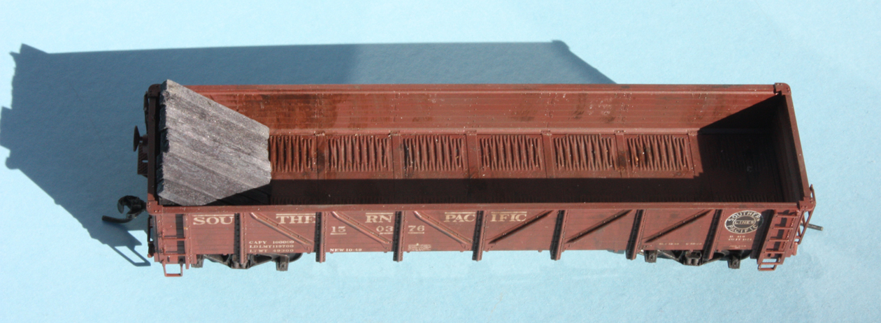
     Some kind of “test session” was especially appropriate, because I am in the midst of introducing several new features in the operation. Probably the most visible new feature is that the final remaining uncompleted track on the layout, Track 7 at Ballard, is now partly completed, and the crews had a loaded car to pick up at one of the industries on Track 7, the Union Brass Foundry (a Classic Miniatures kit). You can see the location of this track in my schematic map of Ballard in an earlier post (you will find it at this link: https://modelingthesp.blogspot.com/2018/06/my-ballard-track-arrangement.html ). Here’s the pickup, from the foundry at left, just passing Jupiter Pump and Compressor at right.


     Something I want to get right is that I am still learning how the “layout clock” works best. I described in a prior post how I want this to work, including my preference for “actual time,” that is, a 1:1 clock ratio (that post is here: https://modelingthesp.blogspot.com/2018/05/an-operating-session-with-clock-and.html ).
     The use of a clock set to a particular starting time, even if 1:1 speed, allows me to choose which parts of the timetable for the main line are active. I have discussed previously the way I can fit my operating session time requirements into the actual prototype timetable for the Coast Route (see that post at: https://modelingthesp.blogspot.com/2019/02/timetable-planning-for-operation.html ).
     I have done this “time slot planning” for previous sessions, and once again, it worked well this weekend, with some small tweaks to the details. I also used a line-up to inform Shumala crews, an idea I’ve discussed previously: https://modelingthesp.blogspot.com/2019/01/line-ups-for-operating.html ).
     And last but not least, I introduced the blue-flag paper work that I described in a recent post, intended to make operators more aware of the presence of the flags (you can read my prior post on this topic at: https://modelingthesp.blogspot.com/2019/02/blue-flag-awareness-part-2.html ). As it turned out, there were no critical flag-time issues in this particular session, so I guess it wasn’t really tested. But I was glad to include it, and it will continue in future sessions.
     As usual this weekend, we had duplicate sessions on Saturday and Sunday, with two two-man crews each day. I calculate these to have been the 42nd and 43rd sessions on this layout in its Berkeley form (there were a couple of dozen sessions when I lived in Pittsburgh). It was especially nice to have a first-time visitor present to operate, veteran modeler Verne Alexander, and he formed a crew with John Rodgers. In the photo below, John is at left while working at Shumala, evidently puzzling over a challenge in the paperwork. The photo includes the layout clock on the far wall.


     The other crew was Seth Neuman and Jeff Aley, pictured below when it was their turn to do the switching at Shumala. Jeff was the conductor and Seth the engineer in this view.


     On Sunday, two new crews took on a session of the same pattern, which is what I usually arrange. On this day, one of the crews was Jim Radkey and Bryn Ekroot, shown below at Ballard on the layout, with Bryn at right. It looks like Bryn was still developing his switch list in this view, while Jim appears to be in the middle of a switching move.


     The second crew Sunday was Pat LaTorres and Ed Slintak. They are shown below when it was their turn at Shumala.


     These two operating sessions of course tested once again, as all sessions do, the trackwork, electrical arrangements, rolling stock, and scenery, but as I described, a few additional features were included (and tested) as well. I was pleased with how well it all worked, and I’m looking forward to BayRails.
Tony Thompson

Monday, February 25, 2019

Restoring a Chateau Martin wine car

I have from time to time in this  blog posted commentary about wine, both as an industrial commodity that was shipped by rail (see that post at: https://modelingthesp.blogspot.com/2012/02/wine-as-industrial-commodity.html ) and also several posts about wine tank cars. (The latter are most easily found by using the search box at right with “wine” or “wine tank cars” as search terms.)
     In the present post I want to report about my restoration of an ancient Laconia Industries HO scale car kit, decorated for Chateau Martin wines (incidentally, pronounced “mar-tinn” instead of “mar-teen”).
     (I have mentioned the background of Chateau Martin before, including mention in the blog post cited in the previous paragraph. To summarize, the Chateau Martin company, owned by Eastern Wine Corporation of New York, shipped bulk wines from California to be bottled in the Bronx. For much more on Chateau Martin, I highly recommend the web page Jim Lancaster has put together. Here’s a link, if you haven’t already seen Jim’s compilation: http://coastdaylight.com/chatmart/cmwx_roster_1.html .)
     The Chateau Martin cars, painted a vivid burgundy color, are extensively pictured on Jim’s page, but here’s a photo he doesn’t include, by Morris Abowitz at Los Angeles in 1964, from the Bill Sheehan collection:


These cars contained internal tanks and thus were classified as tank cars despite their external appearance; the Chateau Martin former express reefers became AAR Class BMT. Such cars were not refrigerated — they were essentially insulated tank cars — and had no ice hatches.
     With that background, let’s return to the Laconia Industries kit, with its correctly-colored sides. The “Laconia” name is interesting. There was in fact a Laconia Car Company, located in Laconia, New Hampshire, building prototype railroad cars, in the years from 1848 to 1928. In 1939, ads announced a new Laconia Industries HO scale model manufacturer, whose kit designer was the last car designer at the Laconia Car Company!
     In 1951, the company moved to Stockton, California. In 1955, it merged with Binkley Models of Inglewood, California, though the two lines each continued to be offered under its own name. In 1962 both went out of business.
     Laconia Industries was probably best known for their foil-printed car sides, with full color paint schemes lithographed onto foil,which was in turn bonded to cardboard car sides. Most of the cars so treated were billboard reefers of the pre-1934 variety, but there were a few exceptions. This Chateau Martin car is one of them, since it represents a paint scheme that ran into the 1970s. Shown below is an Internet photo of a Laconia kit box from the days they were in Stockton. Different kits had different box colors.


     This car kit dates from the 1950s at the latest, and though upgrading details on old models can be nice, I think a case can be made for leaving a car like this as much in original arrangement as possible. That meant I would only be correcting a few of the coarser details of the model. But one defect was glaringly obvious. The car corners showed that the car sides and ends did not meet cleanly. I don’t know what the original kit directions intended to be done here, only that the model as I received it isn’t okay.


     One option occurred to me right away. I could place a square strip, perhaps of styrene, right in that corner to fill the gap, and make it look far better. But then I would have to match the paint color. And if I could match the paint color, that would also permit touching up a few spots where the color on the foil had been nicked. So I tried to see if I could find a match.
     The color of this model is always called “magenta,” and it certainly does look like that color.  So a first cut at matching would be to find a paint that is in fact called magenta. As it happens, there is an acrylic point  from Acrylicos Vallejo or AV (for more on these paints see my comments at: https://modelingthesp.blogspot.com/2019/02/using-vallejo-paints.html ), their no. 70.945 in the Model Color series, that is called “magenta.” And it actually does match pretty well. This is to some extent luck, of course, but it works out in this case.
     With ability to match the paint, I decided to place the styrene strips to fill the car corners. What would fit in each of my corners was a scale 2 x 2-inch Evergreen strip, and I attached it with canopy glue. Most of these corners were nicely filled with this styrene strip, though one of them required some sanding of the strip before installing it. Here is the car at this point.


     Then I brush-painted those corners, and the result is below. You can see that there is some magenta overpaint onto areas of the black hardware, from painting the corners, but it was easy to touch up those errors with black when painting was done.


I also want to add some streaking of dirt onto the roof, but will leave the sides as they are. The fading with age of the Laconia kit sides is probably realistic, and the car can start serving on my layout in that form.
     Many older models in HO scale look fairly crude by today’s standards, but some of them have qualities that still look good. In my opinion, this is one of them, and I will enjoy seeing this car in service on my layout.
Tony Thompson

Friday, February 22, 2019

Powering turnouts

I have a general standard as to how turnouts are thrown on my layout. I want them to be hand-thrown wherever possible. Most of my layout is a branch line, and certainly turnouts on such trackage were hand-thrown on the prototype. Even switches on the segment of the Coast Division main line that I model would have been hand-thrown in my modeling year of 1953.
     But sometimes one may not wish to use a “standard” hobby ground throw. I have mentioned previously that I dislike the immense and out-of-scale size of Caboose Industries ground throws, and have replaced them with Bitter Creek ground throws wherever possible. (see for example my post at: https://modelingthesp.blogspot.com/2017/03/choosing-ground-throws.html ). But there are still times when I don’t want visitors to have to reach too far into the layout to throw a switch.
     I haven’t described it anywhere in this blog (and perhaps I should), but I have built rodding for two mechanically operated turnouts, engaged by push-pull handles at the layout fascia. This approach works well when you  have a straight line, perpendicular to the track, that reaches the layout edge. Here is how that fascia area looks:


The two push-pins you see are the handles for push-pull controls for turnouts in the back part of this area of the layout. They are recessed into the fascia so as not to be accidentally bumped or bent.
     But sometimes layout geometry can fight you on this idea. That is my situation at the part of my layout where the town of Ballard transitions to Santa Rosalia, and track makes a 90-degree bend. Rigging manual throws such as shown above in that inside corner really is not workable; operating rods all converge in one area. Moreover, there is limited clearance under parts of that area, due to staging and other things beneath.
     Those problems rule out the very nice Blue Point device, marketed by A-Line, which is an excellent design but a little too big for this location. And as I mentioned, the layout geometry at this corner works against a straight-line manual operating rod.
     Originally in this area, I decided to use some old twin-coil switch machines that I had retained from my layout in Pittsburgh, back in the 1990s. In a previous post, I showed how I concealed one such machine (see it at: https://modelingthesp.blogspot.com/2015/05/constructing-section-buildings-part-2.html ). The Kemtron machine I installed was old when I installed it in Pittsburgh, and by now it was really old.
     These twin-coil switch machines are totally reliable in my experience, and the power routing they provide with their auxiliary contacts is effective. But they do throw with a loud “clack,” and the switch throws very fast. Not really the best combination of characteristics.
     Stall-motor switch machines have been around for decades. I successfully used an Electroplumbing machine from American Switch & Signal on my layout in Pittsburgh. More recently the Tortoise machine (produced and sold by Circuitron) has become almost ubiquitous on North American layouts. But the Tortoise is a pretty big device, and wouldn’t fit under the layout area in question.
     I decided to try some of the newer servo-type switch motors, like the ones sold by Model Railroad Control Systems. (See their product description at: http://www.modelrailroadcontrolsystems.com/mp1-version-2-switch-motor/ which includes ordering capability, and, if you like, view also the manufacturer’s product brochure [made by a company called MTB in the Czech Republic] at: http://www.modelrailroadcontrolsystems.com/content/MP1%20brochure.pdf ). Here is what it looks like. The contacts in the green area are the wiring connections. The red part is the slider that moves the throw bar of the turnout. The whole device is only 1.5 inches square and less than 3/4-inch tall.


This machine is not a stall motor, but has limit switches that turn off the motor when a preset movement limit is reached. You can choose the amount of throw; I found the 3 mm setting to work fine on HO scale turnouts. 
     I installed one of these motors right where the Kemtron twin-coil used to be. Here is a view of it in place, with both the power wires for the motor, and the auxiliary wiring for track power to the frog, all installed. I have a simple SPDT switch to control this motor.


The wiring coming from two sides is derived from the locations of connections to the prior twin-coil machine and are not optimum for the MP1, but they work. And by the way, this machine doesn’t have to be surface mounted; it works equally well mounted under the layout. This one just happens to be in an area where under-layout mounting would be a challenge.
     The switch motor, of course, is not exposed like the above photo when the layout is being operated, but as was arranged for the twin-coil before it, resides inside a maintenance building:


     I will use this motor as part of an upcoming operating session, and will see how it performs. But in my own testing, it seems fine, and its advantages of small size, easy surface mounting, and convenient wiring connections seem good to me.
Tony Thompson

Tuesday, February 19, 2019

Refreshing the layout


There is something I always think about — but often fail to act on — before operating sessions. It has to do with the state of the layout scenery. There are usually a few areas where work is “in progress” and ought to be completed, and always a few areas where the scenic materials have not, as we might say, “aged well.”
     But as I said, all too often I have thought about fixing such problems, but plain old didn’t get to it. Now for a new stimulus. This March in our local area, we are hosting a nationally-invited operating weekend called BayRails. Envisioning visitors from this audience of experienced layout owners and operators makes the maintenance topic, especially scenery, a little more serious.
     In a reminder last fall to all the BayRails layout operating hosts, our organizers Seth Neumann and Jim Providenza sent out a write-up of things that would be useful to be sure about before the event. These ranged from better safety briefings, to clean sinks, to putting away tools, but included some comments on the state of our scenery. To quote the document section entitled ‘broken scenery,’ they said “Take a close look. Scenery gets old, colors fade, trees get broken. Is it time to refresh things a little? How about the ground cover at the edge, at places where people congregate and rub against it? Is the ground a little too bare?”
     Well, this one hit home. I kind of knew I had some worn areas, but until I walked around the layout and looked for them, I did not recognize how much of a problem I had. As one example, here is an area in my layout town of Shumala, where scenic materials have worn completely off the top of the Masonite fascia. Note also the area just below the track, where some paper mache is exposed.

As seen below, adding some of the usual scenic material to this same area not only covers the bare spots but adds some needed foliage. The somewhat larger bush is made from Woodland Scenics’ foliage material (Dark Green, no. F-63), which is easily teased into as much volume as you wish. I like to include these kinds of shrubs as layout vegetation, somewhere in the size scale between ground cover and trees.

      Another area distinctly showing wear, also on the Shumala side of the layout, was to the north of Chamisal Road (that’s the edge of the road at far left). Here again, you can see some bare paper mache in places.


I did a similar fix as with the first example, using scenic materials on hand, mostly Woodland Scenics, but some other makes too. (The tank car had been switched to its destination by this time.)


Then of course there are always other things needing fixing or repair. I noticed just the other day that one of the pit rails in my turntable had escaped its bonds. It’s the right-hand rail below.


This merely requires a little CA in the right places, re-curving the rail to the right arc, and placing a weight on it while it thoroughly sets. Not difficult, but certainly necessary — if we are to use the turntable. 
     All of these kinds of repair or upkeep are quick, simple, and effective. I must remind myself to do more of the same in the future!
Tony Thompson 
 

Saturday, February 16, 2019

Timetable planning for operation

This post amplifies some topics I have discussed previously in my blog, having to do with how I have evolved my use of a timetable for operation of my layout. My layout is set within the Guadalupe Subdivision of Southern Pacific’s Coast Division. As I described in an earlier post (you can read it at: https://modelingthesp.blogspot.com/2012/04/coast-line-operations-1953-for-my.html ), I made a modified timetable just for that subdivision.
     I explained in one of my Model Railroad Hobbyist (MRH) columns how I constructed all the various parts of my timetable, removing some station names from the actual Timetable 164 of September, 1953, but keeping the actual train times. I showed this as Figure 12 in the issue for October 2014 (you can download or read on-line this or any issue of MRH, for free, at their website, www.mrhmag.com ).
     I also wrote a kind of introduction to that column for the blog, a post which can be found at: https://modelingthesp.blogspot.com/2014/10/my-column-on-timetable-construction.html  Reproduced below is that compacted timetable.(You can click on the image to enlarge it.)

When we use this timetable, we refer to the clock in the layout room, which operates at a 1:1 ratio (that is, normal time rate) but is set to the desired starting time for the session, independent of actual time in the world.
     What is important in this timetable for my operation is that it contains trains I cannot run (a realistic Daylight or Lark would have to have a dozen or more cars, and  I simply cannot stage that big a train), or trains I can only run occasionally, such as the mail train, nos. 71 and 72, which was only occasionally during the year small enough that I can operate it. What does that mean?
     First, it means that I can set an operating session to start and finish (on the layout clock) outside the times in which those inconvenient trains would run. So, for example, I can operate a morning session, and would start it at 9:20 a.m., because at that time, no. 72 has just passed. However, no. 99 will be along about 12:30 PM, so either we would need to finish the session in three hours (usually it would take a little longer), or I have to issue a train order that 99 is running late. The morning schedule also includes through freight no. 914, though like most Coast Division freights, it often runs a little late. I might add an extra train or a second section of 914.
     These considerations mean that a crew working at Shumala, the junction on my layout between the Coast Division main and the Santa Rosalia Branch, knows at about 11 a.m. what train this is, and in fact they have been expecting it; from the example just given, it would be no. 914.


     A second option is an afternoon session, which would conveniently start on the layout clock at 1:50 PM, at which time no. 98 has just passed. This means that through freights nos. 912 and 913 would both pass Shumala during a normal session, but no passenger trains during the session. An even more “open” session can be conducted in the evening, say starting at 6 PM. Now the two freight trains that will operate are nos. 915 and 918, and there is no looming first-class train coming at us.
     There will normally also be one or more of the Guadalupe Local and/or Surf Turn trains passing by on the main line, and these usually drop off and pick up cars at Shumala, the interchange point for the branch line to Santa Rosalia that makes up most of the layout.
     So for any session, I need only to tell the operating crews whether it is AM or PM on the layout clock, and they can consult their timetables to know what to watch for on the main line. They may also be helped by having a line-up passed to them by the Shumala agent, as I described in an earlier blog post, which is at: https://modelingthesp.blogspot.com/2019/01/line-ups-for-operating.html .
     These time slots help define how I can efficiently operate my layout, subject to actual SP train scheduling, yet working within the constraints of my layout capabilities.
Tony Thompson

Wednesday, February 13, 2019

Union Oil gas station, Part 4

This series of posts is about modifying a City Classics kit for a service station to fit my layout and to serve as a Union 76 gas station of the 1950s. The preceding post, Part 3, was about assembling the station building and preparing a pad for it with appropriate driveways from street level (it can be found at this link: http://modelingthesp.blogspot.com/2018/09/union-oil-gas-station-part-3.html ). Links to the first two posts on this topic can also be found in that Part 3 post.
     In the previous post, I showed the assembled building without rear wall or roof. But the important part about the building at that point is that I had kitbashed it to be smaller and fit better into the space on my layout. (See the post about the changes at: http://modelingthesp.blogspot.com/2018/08/union-oil-gas-station-part-2.html ). That means that not only the rear wall, but also the roof provided in the kit would need to be modified for the smaller building. I went ahead and did those modifications. Shown below is the building (complete with Union 76 orange stripe) and roof piece. The roof is obviously unpainted, and not glued on at this point, as the window glazing and interior need to be added.


You will notice here that I painted the frame of the office windows light gray, to suggest an aluminum window frame. I also painted the restroom doors dark gray, as I recall that being the case at Union stations back in the day.
     At this point, I returned to the kit directions to make sure that I did everything that needed to be done before gluing the roof. As I mentioned, the directions recommend adding the window glazing and also the printed interior walls and floor for the office area in the station front corner.
     I began by attaching rectangles of clear styrene provided in the kit, at each window opening, using canopy glue. (this is a great adhesive for this application, because it sticks really well, doesn’t attack styrene, and dries clear. (For further comments about the value of canopy glue, see my prior post at: https://modelingthesp.blogspot.com/2013/05/a-few-words-in-praise-of-canopy-glue.html .) I then attached the printed floor with canopy glue also. Here is the floor in place. Note that I have not yet cemented the building to its base.


     Because my gas station will be fairly near the edge of the layout, and accordingly visitors will be able to see into the station office through the large windows, I decided to add a counter to the back wall inside. This is just folded paper, with the original counter front moved outward. 


     When the interior walls were added, I also placed a desk by the front window.Then I added small rectangles of paper on the surfaces, and a few miscellaneous objects, just so that there were “things” in view. I also added some color to the back wall.


     Next the module shown above was glued into the building, using the flaps that you can see at each edge, using canopy glue. This completed the interior work I wanted to do.
     At this point, I was beginning to think about the personnel that I could model at this service station. Like most oil companies in the early 1950s, Union Oil had a standard uniform for attendants. Certainly in an earlier era, this uniform for Union Oil had been all white, pants and shirt. They had nicknamed it “Minute Man Service,” and here is an example of a sign publicizing it. (internet photo)


Later in the 1950s, there was a change to dark blue pants with the white shirt, and I don’t know when this change was made. But here is a 1959 sign showing this changed uniform. The hat has changed also. I think the blue pants looks good, and will adopt that for my service station personnel, though as I said, I am not sure the change had been made by 1953. (internet photo)


     Next in line for the detailing of this gas station is the gas pump island and some of the other details provided by City Classics in this kit. I will address those in a following post.
Tony Thompson

Sunday, February 10, 2019

Blue flag awareness, Part 2

I have wrestled in previous operating sessions with the fact that scale-size blue flags are neither large enough nor of sufficiently eye-catching color to be readily noticed by operating crews. I illustrated this problem in a previous post (you can find it at: https://modelingthesp.blogspot.com/2018/10/blue-flag-awareness.html ). In that post, I mentioned the creative and effective idea used by Bob Hanmer on his layout, to employ a form identifying tracks for which access was temporarily blocked, and to provide that form to switch crews.
     To illustrate, I will repeat a photo shown in the post just cited, of one of my blue flags in place at the Union Oil unloading track in my layout town of Ballard. It is right past the edge of the road. Certainly if you look for it, it’s there, but I have already had crews run locomotives right over flags like this.


     I decided to create a form with the same goals as the one Bob created, but to use it in a different way. First, his form is a good approach for an industry (a large paper mill) that is switched throughout the day, with multiple cars moved to and from multiple tracks. I don’t have any industries like that. Instead, I have industries that may not even be switched every day, but which do employ blue flags for hazards like tank cars connected for unloading.
     Second, my framework for communication with switch crews is in the form of messages and paperwork from the agent in each town. A form that is intended to occupy a track slot in a waybill box or rack is not readily part of that framework; indeed, I have no waybill racks on my layout. Thus I decided to make up a form that could be part of the message package that crews pick up at each town.
     My conclusion was that a slip the size and shape of the waybills I use on the layout would permit these blue flag notices to be part of waybill package. I used the ideas of the Hanmer form to make these, but designed as a single-use form that an agent could fill out and hand to a crew.


The color blue is chosen for the obvious reason.
     This clearly is very simple to fill out, and can be done during an operating session in real time, depending on how a crew’s work is going, or can be done in advance so that work has to be structured around the restriction. As the session “supervisor,” I can remove the blue flag at the designated time, so the crew has access to the restricted track. Here’s an example.


     I will be trying this idea at my next operating session, to see how well it works, and whether there are drawbacks to different ways of using it. But my hope is that it “empowers” my scale-size blue flags to do their job.
Tony Thompson

Thursday, February 7, 2019

Using Vallejo paints

The very large line of acrylic paint from Acrylicos Vallejo (AV) has come into focus for model railroaders in recent years, in the continuing aftermath of the 2013 demise of Floquil, once the most widely used paint for railroad colors. To take their place, there are a number of new paint options.
     To begin with, there are the traditional types of solvent-based paints. There is the generally excellent line from TruColor, though some find these paints hard to use (I have not had any problems). There is a very nice line of paint from Tamiya, which I have commented on before (my post at: https://modelingthesp.blogspot.com/2018/08/a-shout-out-for-tamiya-products.html ). And of course, Scalecoat remains available, an excellent line of paint in many ways, as do Star Brand paints, and I use both of them myself for some applications.
     But Vallejo paints (buh-LAY-ho), the subject of this column, are water-base acrylics. Paints of this kind have always had their place in the model railroad landscape, most commonly in Floquil’s former line of Polly Scale paint.
     Today, if the topic is acrylics, one may well think first of Vallejo paints for specific gradations of color. (Artist’s tube acrylic paints, such as the widely used Liquitex line, are long-running standards in the art world. I rely on them myself for weathering applications.) But returning to Vallejo, if you are interested in an introduction to this line, you can visit the AV site, and they offer a number of nice, downloadable paint charts and introductions (see those at: https://acrylicosvallejo.com/en/downloads/ ).
     Before going further, I want to warmly recommend the very nicely done and complete “Guide to Acrylic Painting” (subtitled “. . . in a post-Floquil World”) by Joe Fugate of Model Railroad Hobbyist. This is a PDF document available from the MRH website if you are a subscriber (standard subscriptions are free); you can download it from this link: https://model-railroad-hobbyist.com/subscribers-only/painting/acrylics .
     The most fundamental difference within the AV paint line for model railroaders probably is the distinction between their paints intended for brush application, called Model Color, and including a few other series aimed at specific users in military or fantasy modeling, versus Model Air, pre-thinned for airbrushing. You can also use the AV thinner to thin Model Color paints for airbrushing, but they state that the colors will be brighter if you start with Model Air. I have no experience yet either way on that point,
     The first colors I wanted to try were some that I could use as scenery colors (brown and gray), along with something that was recommended as an okay Boxcar Red. The containers have an eye-dropper like dispenser under the lid, which allows storing these paints for extended time.


The colors shown are all Model Color, from left to right, they are Burnt Red (70.814) and Neutral Gray (70.992), both in the Acrylic Color series, and Flat Earth (70.983) and Beige Brown (90.875), both in the Panzer series. These are just four examples of a very wide range of colors. I have already purchased and used other AV colors, such as U.S. military Olive Drab, for military vehicles.
     I have used these colors so far with brush application only, and have not yet had occasion to thin them for airbrushing, though I feel confident that there will not be problems. They are very good, intense colors and quite opaque as applied with a brush, all you could ask in that kind of application. They seem to adhere well to various materials and are self-leveling and pretty quick drying.
     For background, although AV is headquartered today in Spain, the company was founded in 1965 in New Jersey, before moving to Spain in 1969 to serve primarily the cartoon film industry in Europe (in the day before digital film making, when those cartoons were painted). By 1972, the first professional artist’s acrylics were marketed by AV. Needless to say, these are high-quality paints and are not just hobby products. The company remains a family company, still directed by Amadeo Vallejo, and today their paints are sold world-wide.
     These paints are readily available on the internet, but if, like me, you prefer to visit a store to see the colors in person, your best bets are war-gaming stores and plastic military model stores, along with good-quality art stores. Most model railroad hobby shops do not carry Vallejo paints, at least at this writing. Of course, once you know that a particular Vallejo color works for one of your specific applications in modeling, you can obtain more of it, or Model Air instead of Model Color, via the internet.
     If you have no experience with acrylic paints, I urge you to give these a try. True, the colors are not model railroad colors, but you can use the Model Railroad Hobbyist download I mentioned to come up with reasonable color matches to the more familiar railroad colors. Vallejo paints are high quality and I recommend them.
Tony Thompson

Monday, February 4, 2019

My column in the February Model Railroad Hobbyist

Another of my magazine columns in the “Getting Real” series has appeared in the February 2019 issue of the on-line publication Model Railroad Hobbyist. The magazine since its inception has been free on-line or to download (visit their website at www.mrhmag.com ), but recently parts of the content have become subscription-only, in an enlarged magazine called “Running Extra.” It only costs $1.99 extra per issue, so not expensive, but this does represent a change in the availability of MRH. And my column this month does fall into “Running Extra.”
     My topic was the prototype information I collected, interpreted, and put to use in choosing a locomotive fleet for my layout. These are Southern Pacific steam and diesel locomotives appropriate for my 1953 modeling year. I provided a modest bibliography of published books and articles, along with some electronic resources, and including links to a couple of earlier posts in this blog on the topic.
     Steam predominates on my layout, consistent with what I know about SP motive power on the Coast Division in 1953, and I showed both prototype and model photos of various locomotives I chose for my fleet. For example, one of several Harriman Consolidations I roster is SP 2752, an engine long assigned to San Luis Obispo and thus likely to be seen operating on the mythical branchline I model, only 20 or so miles south of San Luis. Here is that engine switching the Union Oil Company spur in my layout town of Ballard, part of the work of this day’s Santa Rosalia Branch local.


This is a pretty stock Key Imports Class C-9 SP Consolidation. This is a photo not used in the column, as are the other images in this post.
     In addition to small steam like the Consolidations, I have also modeled one of the two Mikado wheel arrangements assigned at San Luis Obispo, SP 3251. It often operates in my layout sessions on the Surf Turn or the Guadalupe Local. Here we see it about to depart the branchline junction at Shumala, after doing its switching work there.


Not having been able to find a brass model of an SP Pacific Lines Class Mk-6 Mikado, the class to which SP 3251 was assigned, I obtained a Hallmark Models import of a T&NO Class Mk-5. Alan Massi redetailed the locomotive to match the Pacific Lines engines, and also repowered the model and added a DCC decoder in the Vanderbilt tender.
     Finally, I did spend some time in the column discussing big steam, such as SP’s handsome Mountain types. As I commented in a recent blog post, the Athearn Genesis version of this locomotive is an excellent and well-detailed model (see that post at: https://modelingthesp.blogspot.com/2018/12/the-sp-4-8-2-from-athearn.html  ). Here is my model, SP 4349, pulling an extra passenger train and just passing the Shumala depot.


     It has been fun, over the years, to accumulate, interpret and understand the many published and unpublished resources that document SP steam and diesel power. That background has been the basis for my modeling choices, and was summarized in my column in the February MRH.
Tony Thompson

Friday, February 1, 2019

Open-car loads: ties in gondolas

In the last few months, I have explored some of the trackside evidence of railroad track maintenance, including such things as rail racks and tie piles (both these items were described in earlier posts, for example the one at: https://modelingthesp.blogspot.com/2018/12/tie-piles-and-rail-racks-modeling.html ). But these ties don’t magically appear at trackside. Naturally they are shipped to where they are needed. Nowadays ties are shipped in bundles with steel strapping, but in the transition era that I model, they were shipped loose, usually in gondolas, sometimes on flat cars.
     One example of how ties might be shipped is shown in an ARA diagram, from the Loading Rules book of 1926 (most diagrams remained in force for decades), page 62. It’s shown below.


Note the stack of cross-wise ties at the left end, with all other ties leaned against that pile. This arrangement would be fairly straightforward to load and unload by hand. (Of course, the 200-pound weight of a prototype tie is not easy to handle.) It is also fairly stable in the car, and won’t be seriously perturbed by draft and buff loads in transit.
     I began to build a load like the one shown above by making up the pile of ties that go in the end of the car. This is of course a simple stack. I used the same Model Hobbies ties previously mentioned (see my earlier post at: https://modelingthesp.blogspot.com/2018/12/tie-piles-and-rail-racks-modeling.html ) and canopy glue. This is quick and easy.


     When this pile is placed in an example gondola (here one of SP’s composite GS cars, a Red Caboose model), it fits as expected. This is how I chose the height of my pile, 6 ties high.


    Then layers of ties need to be laid over the end pile. These of course hide the pile in the end, as you see in the photo below. (It could be argued that you don’t need to use ties for the end pile, since it will be hidden.) The single layer you see here is laid in loose, not glued. I intend to  make both a full load and partial loads, so that I can ship both kinds (the latter would represent a load delivered in two parts to two locations).


     It is an option to simply lay all the ties into the car by hand, leaving them loose, and I know a modeler who does tie loads that way. (Then, of course, it’s easy to model a partial load by just removing part of the load.) I prefer to make at least some glued layers to simplify loading the car. My method is to make up “layers” of ties by gluing 9 ties side by side for each layer. The photo below includes few loose ties for scale.


     One can of course make up a few of these layers, and intersperse loose ties for flexibility. Here is a partially loaded car:


     What may not be very evident above is the restraint of the tie pile. I recall seeing a photo somewhere, that showed a partial load of ties like this. The pile in one end of the car was restrained by a single tie crosswise in the car, with wooden wedges driven at each end to hold it in place. I guess a workman could just use an axe to whack a couple of wedges from a piece of scrap wood. But this indicates a way that such a load can be modeled. Looking down into the car, you can see that I just added small pieces of stripwood at each end of the crosswise tie. (You can click on the image to enlarge if you want.)


     I can now make waybills to deliver loads of ties, whether partial or full loads, to my “outfit track” on the layout, where various work cars are usually spotted, and where I envision that track crews would be headquartered. This adds a little variation to the many revenue loads that get switched in an operating session.
Tony Thompson