Wednesday, December 30, 2020

Modeling freight traffic, Coast Line, Part 14

 I have from time to time described the ways I operate my layout to convey the larger railroad of which it’s a part (the Southern Pacific’s Coast Route). The main activity on the layout is the Santa Rosalia Branch, but since a portion of Coast Division main line is included, I try to provide activity there to reflect the SP’s traffic.

Some time back I mentioned how the mainline trains on my layout are used for this purpose, with a variety of power and consists to suit the situation. That post included mention of automobiles and auto parts (see the post at: https://modelingthesp.blogspot.com/2017/10/the-role-of-mainline-trains-on-branch.html ).

It’s known that the automobile-industry traffic was important on the Coast Route, as shown, among other places, by the SP’s “Condensed Perishable, Merchandise and Manifest Train Schedules” (described in an earlier post: https://modelingthesp.blogspot.com/2017/09/modeling-freight-traffic-coast-line.html ). In later years, these schedules were in the form of booklets like this one (title slightly changed):

But schedules only tell you about the trains. The traffic in them reqires more information.  I have provided a detailed look at some of the prototype sources of much auto industry traffic in a previous post (that post can be found at the following link: https://modelingthesp.blogspot.com/2017/12/understanding-auto-industry-traffic.html ).

Here is an example of an eastward train (likely the “Los Angeles Manifest” train, symbol LA, as identified in earlier posts), emerging from the tunnel just outside Shumala. The time is late morning, and the train number is 914. This train moves mostly loads of auto parts, that arrived via the Overland Route into the Bay Area yesterday, and are en route to Southern California auto plants.

Consists like these allow me to operate the several varieties of automobile box cars that I have on my freight car roster, particularly the 50-foot variety. I have described my approach to creating this roster in a post that was part of a series about my entire roster, including comments on traffic (the post is here: http://modelingthesp.blogspot.com/2011/02/choosing-model-car-fleet-4-automobile.html ). 

The same train was also photographed just passing the Shumala depot. as you see below. The auto cars in this view are all 50-foot double-door cars, but I vary this group of cars by including 50-foot single-door cars, and 40-foot double doors (the latter two types primarily in auto parts service). Some of these cars may contain partial loads, if partly unloaded at Bay Area auto plants, before completing their journey at Southern California plants.

It’s worth mentioning that these loaded auto parts cars, en route to Los Angeles, are mirrored in the opposite direction by empty auto cars returning along their service route to be reloaded. The companion westward train of this type to the LA Manifest was the San Francisco Manifest (SF). I operate an SF in some operating sessions, normally a late afternoon train but sometimes ending up moving earlier.

The photo above portrays this “other side” of the LA Manifest that was shown in the first photos above, and its auto cars here at the end of the train, passing Shumala, are a mixture of 40-foot and 50-foot cars, and one single-door car. In this direction, most cars are empty, on the way to be reloaded.

These two trains, the LA and the SF, were the “hot” or through trains. The SP had essentially two types of manifest freights, those that operated straight through to the destination area (such as the LA and SF that I have shown here), and other manifests that picked up additional freight cars at intermediate points (Watsonville Junction, San Luis Obispo, Santa Barbara). These were the Coast Line Manifest (CLM) eastward, and the Golden Gate Manifest (GGM) westward.

So among other features, these “general freights” could well include lower-priority cars, such as empty gondolas. Accordingly, I sometimes operate at least one train that could be called “general freight,” that is, a manifest train of lower priority, with a corresponding consist. All these mainline trains contribute to the identity of the Coast Division main track on my layout.

Tony Thompson

Sunday, December 27, 2020

Freight car graffiti, Part 18: 60-foot box cars

In a long series of posts, mostly from last spring, I showed application of various sorts of graffiti to a variety of freight cars, mostly the modern fleet of my friend Seth Neumann, whose layout is set in 1996. Many of the cars shown in the earlier series were cement cars, or sand and gravel hoppers (see for example the last previous post: https://modelingthesp.blogspot.com/2020/06/freight-graffiti-part-16-granite-rock.html ). For others in the series, just use “freight car graffiti” as the search term in the search box at right.

Many of those posts showed the use of commercial decals for graffiti sources, but I included additional material on using paper overlays, and for tagging. The fundamentals of these applications stem from my article in Model Railroad Hobbyist, in the issue for January 2020, and summarized in a blog post (see it at: https://modelingthesp.blogspot.com/2020/01/freight-car-graffiti-part-2.html ).  

For the present post, I will begin with one of the typical 60-foot cars of this type. Below I show one of Seth’s models, with a haze of weathering on it. This is the kind of car I am addressing in the present blog.

For these cars, I wanted a moderate amount of side weathering, but with real rust and dirt on the roofs, and perhaps a single graffiti piece on each side. My authority for graffiti appearance, and in fact for copying of actual graffiti images, is the book, Freight Train Graffiti, by Roger Gastman, Darin Rowland and Ian Sattler (Abrams Books, New York 2006). 

I will also add, as I’ve said several times, you may hate or love graffiti on freight cars, your call of course, but any time after the mid-1980s, they are simply reality. Modeling without them speaks for itself.

To begin, I worked on a Cotton Belt car like the above image, though with a different car number. For this car, on the left side, I used Microscale decal set 87-1523, as you see below. The car has also been weathered after decal application.

Then on the right side, I used Microscale 87-1534 and 1535. On both sides of this car, I used a fine-tip felt pen to add some tags. For the subject of tagging, by the way, I  wrote an entire post to cover this sub-set of the graffiti world (see it at: https://modelingthesp.blogspot.com/2020/04/freight-car-graffiti-part-11-tagging.html ). I will say more about roof treatments below.

The other car I want to present is the same car body as the model above, but lettered for Missouri Pacific. The left side of this car used Microscale 87-1535, and some small decals from Microscale 87-243. Here again, the model as you see it here has been weathered after decaling. Tags were also added, which you may see better if you click on the image to enlarge it.

On the right side of this car, I used decals from Microscale sets 87-1534 and 1535. This photo shows a little of the roof treatment also. Note that the decals have settled down nicely over the ribs.

Finally, since I have been mentioning roof treatments, shown below are the same two cars just presented, seen from above, with their X-panel roofs dirtied and with some patches of rust added. The upper roof in this view is the MP car just discussed; the lower one is the Cotton Belt car shown earlier in this post. In the more modern era of these cars, heavy deposits of soot on roofs were largely absent, compared to the transition era, but rust failure, incipient or widespread, was and is common on galvanized roof sheets.

These two cars are the beginning of a larger group of cars of the same type, to which I will return in future posts. These two, however, do show the basic approach I am using.

Tony Thompson

Thursday, December 24, 2020

Making better roads, Part 3

In the preceding post about my upgrades to Bromela Road on my layout, in the town of Ballard, I described how I went about making the pavement marking warning of a grade crossing ahead. I used an actual standards drawing of this marking, and simply cut out and pasted down the paper parts. That post is at this link: https://modelingthesp.blogspot.com/2020/09/makinag-better-roads-part-2.html

I mentioned in that previous post that I would soften the bright-looking white letters and “X” marking on the roadway with weathering powder. I wasn’t happy with how this looked, so decided to use my “regular” color for painted markings on darkish-color roads, SP Lettering Gray, and painted the paper parts that way. (If I were doing it again, it would be easier to paint the paper parts before installing.) I show the current state of it below. This may be compared to the white version shown in the previous post (link in the paragraph above).

Note also in the photo above that the roadside edges remain simply painted, without scenery materials. My base color for dirt is Rust-Oleum “Nutmeg,” though as my layout locale nears the coast, the soil ought to become more sandy. To that end, I mix in some of the Rust-Oleum “Almond” color. blended with proportions to suit. Along roadsides, I have also been adding Woodland Scenics “Fine Turf” as Green Grass, no.T1345.

With those features done, I placed the Advance Warning Sign, as it is called, the round yellow sign that warns motorists that they are approaching a railroad crossing. In my article on railroad crossings in Model Railroad Hobbyist (July 2020 issue, in the Running Extra section), I showed these signs in model form. Here is the one on Bromela Road

Though not a view any operator or visitor could access, this look down Bromela Road shows the Warning Sign a little in advance of the pavement marking.

      Speed limit signs. I realized that none of my layout roads have speed limit signs. They add flavor even if not absolutely necessary. These signs were standardized nationally in the 1930s, though some localities continued to have their own variations (as with so many topics in model railroading, photographs are your best authority for your era). In my Model Railroad Hobbyist article (July 2020), I discussed how in the past, most states had their own standards for such things, and these varied over time.

Example of the national-standard signs can be found in the MUTCD (Manual of Uniform Traffic Safety Devices) for your era, available on line; but essentially those same standard signs are still in use, so you can simply go on line to a seller of real signs, download the sign images, size them for HO scale, and print them out. They are black and white, so any laser printer will deliver a good sign. Here are two I have used. 

I used Evergreen scale 4 x 4-inch styrene for the posts. For the look of unpainted wood posts, as are common in highway installation, I painted the styrene posts with Tamiya “Desert Yellow,” no. XF-59. I find this a suitable wood color that looks reasonable as somewhat new and not heavily aged wood.

Below is one example of a speed sign in place. This is Pismo Dunes Road in East Shumala, a moderately busy road in this area, thus the 35 mph limit. The SP stock pen is at right.

Another example uses a 25 mph limit. This part of Willow Lake Road is right alongside the SP depot in my town of Santa Rosalia, and near entrances to industry loading areas, and thus has a lower speed limit. There’s nothing tied up in the harbor at the moment except a rowboat.

With the addition of these signs, my work on several roads on the layout is approaching completion, but I still have to deal with Bromela Road’s fairly sharp turn at the tracks on the south side of the branch. This would often call for signs warning of the sharp turn (the MUTCD makes clear that placement of these depends on the judgement of the highway engineer as to whether they are necessary). I will show my solution to the problem in a following post.

Tony Thompson

Monday, December 21, 2020

Pennsy freight cars, Part 6: modeling the wagon-tops

In the previous post in this series, I introduced the wagon-top box cars (or “round roof” cars, as they are sometimes termed) of the Pennsylvania Railroad.  By the early 1950s, they comprised the second largest group of PRR box cars, after the immense Class X29 fleet. And like the X29, they were a very distinctive design, and indeed can be called a signature car. That post is here: https://modelingthesp.blogspot.com/2020/11/pennsy-freight-cars-part-5-round-roof.html

Over the years, there have been a variety of models available for these cars. One might begin with the Athearn metal models of both 40-ft. and 50-ft. cars. These were pretty decent models, having separate ladders and grabs, and accurate bodies. As an example (I don’t own a PRR version), here is the 50-ft. car in DT&I paint. This is an X32A design. (The DT&I was one of several railroads that purchased cars of this design new.)

There once was a Roundhouse styrene version, about which the less said the better. There has for some years been a Bowser “shake the box” molded styrene version, not bad-looking overall but with cast-on details (the separate running board molding is excellent, though). In decorated form, the model has lettering that is not terribly well rendered. Of course the details can be upgraded and proper lettering, such as the decals available from Speedwitch or Middle Division, applied to these cars. Here’s an example, Bowser’s Class X31A, using Speedwitch set D122.

There have been a variety of resin kits produced in HO scale, from West Shore Line and Sunshine. These can sometimes be found for sale on eBay and other on-line sources.

In HO scale brass, there have been several different versions imported (notably by W&R Enterprises), though these tend to be costly and hard to find. Below is a photo of the W&R model, Class X31B, as painted and heavily weathered by Richard Hendrickson. In a nice detail added by Richard, note that the car, originally equipped with automobile racks and thus with a white stripe painted on the right-hand door, has been taken out of that service and the stripe painted over.

There was once a somewhat simplified model of an X31C imported by Nickel Plate Products, and I recently posted descriptions of my work restoring one of those (see the post at: https://modelingthesp.blogspot.com/2020/12/restoring-old-brass-car-part-2.html ). One more example: Railworks some years ago imported a brass model of Class X32A. Though not a great model, it certainly captures all the main features.  

But the big news these days is that Rapido Trains is close to releasing what should be a superb model of the most dominant variation numerically, the X31A single-door car. (They are also doing double-door X31s.) You can visit their website for updates on progress with this model (the page is at: https://rapidotrains.com/products/ho-scale/freight-cars/ho-scale-prr-x31a-boxcar#prettyPhoto ). I don’t know if it’s official, but it’s being said that these will cost $49.95, U.S.  Below is one of their photos of a pilot model, with the inset roof feature quite visible.

The wagon-top cars are really “signature” freight cars of the Pennsylvania Railroad, and deserve inclusion in any model freight car fleet from the 1930s to the 1960s. They were numerous cars and, especially the single-door box car sub-classes, went everywhere.Like the X29, they were ubiquitous in North American railroading, and should be in your fleet, too.

Tony Thompson

Friday, December 18, 2020

Restoring an ancient Athearn metal model

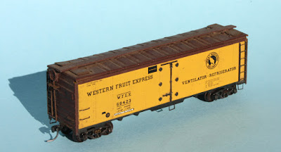
 Some months ago my friend Jim Providenza gave me an old model of an ice refrigerator car, too old a prototype for his 1970-era layout. As it’s a real classic, I accepted gratefully, and decided to explore exactly what it was. I show the model below as I received it. You can notice on this side that the door latch casting is broken.

The model’s car number, 68423, falls within a 250-car order that Western Fruit received from Pacific Car & Foundry in 1949, cars 68400–68649. As it has a wood floor beneath its underframe and pressed-metal hatches, I immediately thought of the Athearn line of metal car body freight cars. 

But Globe Models, prior to its purchase by Athearn in 1951, also offered an HO steel reefer. Which one was it? The great resource for questions like this is the HO Seeker site (see the Athearn page  at: https://hoseeker.net/athearn.htm ), providing many of the Globe and Athearn catalogs, and even kit directions. Looking at the 1950 directions on the site for the Athearn reefer, numerous details matched up with the model I have. It’s an Athearn. Here is that image; you can click to enlarge if you wish.

First up was to replace the broken door latch. That’s simple with a Grandt Lines part from my parts box. Next I turned to the underbody. You can see in Step 2, above, that Athearn provided a one-piece white-metal casting of the bolster, coupler box, and corner braces, but all of this except the bolster had been removed on this model. The reason was that a previous owner had installed Kadee “Talgo” trucks, the ancient style with the straight trip pin and No. 4 couplers with a riveted box cover. I didn’t know that Kadee had even made these back in the 1950s! Sill steps were gone too.

I removed the Talgo trucks (to return to Jim as a memento) and replaced the sill steps with actual Athearn metal parts from my stash of ancient parts. I then body-mounted Kadee coupler boxes with no. 158 whisker couplers, and added a pair of Kadee sprung trucks. The model was also missing its brake rod below the hand brake, so I added that. Then all parts that should be brown (hatch covers, end ladders, brake rod) were painted Tamiya Red Brown (XF-64).

Last part of the present project was to add end numbers, which the original Athearn metal models never had. I used the very handy Walthers set from years ago, “Reefer End Nos,” their set 706800.

The car still needs to have some light weathering, being a recently built car, but that will come later. So this completes the details of this restoration.

These Athearn metal cars were excellent in their day. And in fact their relatively fine pressed metal ladders and stamped sill steps compare favorably with much that we have today, despite being a design of 70 years ago. This model will hold up just fine on my 1953-era layout.

Tony Thompson

Tuesday, December 15, 2020

What’s a Car Distributor?

 The title of this blog my confuse some — if so, read on — but even those who know what the job was about, may not recognize the ramifications in model railroad operations. I have written in a general way about this in previous blogs. For example, I wrote a fairly general description about what most railroads called their Car Service organization (that post can be found at the following link: https://modelingthesp.blogspot.com/2019/09/the-car-service-organization.html ), including a link to an article about car service on the Bangor & Aroostook (BAR).  

A previous post that quoted some railroaders, notably Dave Sprau describing experiences as a relief agent at the NP depot in Snoqualmie, Washington, about how he as an agent would relate to a Car Distributor, was the one here: https://modelingthesp.blogspot.com/2014/04/waybills-part-32-waybill-preparation.html

And on this and other bases, I think we understand that shippers called their local agents to request cars, and agents called a Car Distributor nearest them to obtain that car. But then what happened? That’s what I want to turn to next. But first, it’s first essential to remember that armies of clerks did this kind of work on railroads, before the advent of business computers. 

Above is a an example of yard office clerks in a moderate-size Southern Pacific yard at Gerber, California. The photo appeared in the SP employee magazine, The Bulletin, in April 1952. These people relied heavily on the telephone for their work.

The Southern Pacific, like many railroads, located this activity in the Transportation part of the Operating Department. Its name was Freight Car Service, with subordinate individuals called “car service agents” or clerks. The BAR, as shown in the link in the first paragraph above, had a Chief Car Distributor, and under him, several Car Distributors. Another pattern was to have a Car Distributor and car service clerks under him. (I use the male pronoun here because in the transition era, the immense majority of these people were men.)

So how did it work in an office like the one above? how did the Car Distributor and his staff of clerks do their work? On nearly all railroads, the local agent’s “first thing in the morning” duties included listing the number and disposition of all freight cars spotted in his territory. From these reports, the Car Distributor’s staff would know approximately how many cars will be made empty on-line today.

The Car Distributor’s office also receives, every morning, junction reports of all inbound empty cars being interchanged to their railroad, and a status report from the yard as to how many and what kind of empties are stored in the yard.

Against those stocks of empty cars, they have requests coming from shippers, via local agents, which were all submitted prior to 2 PM  (or some comparable time) the previous afternoon. Now the job is to match up the available empties to the requests. Any requests for car types or sufficient numbers of cars not available will have to be sent to a yard in the adjoining division, though of course part of the job is to anticipate needs, and hold a certain number of empties for expected use.

Recently on the Steam Era Freight Cars email list, an interesting comment was made by Todd Sullivan, who worked a year in the early 1960s as a clerk for the NPT (Northern Pacific Terminal Co.) in Portland, Oregon, a terminal switching railroad owned jointly by NP, UP and SP. He did a variety of jobs, but here is his comment (used with permission) about working in the Car Distributor job.

“In my clerking experience, which included working Car Distributor (essentially the car inventory & supply manager) for two weeks, I found that each industry's traffic manager had a pretty good working knowledge of the cars his company needed on a regular basis. When I received calls requesting empties for loading, the requests were usually very specific, down to the individual car or series number. 

“Also, the Car Distributor had a pretty good knowledge of both (a) car types ordinarily found on the property (we were a terminal switching outfit) and (b) how to decipher the contents of the ORER. As a side note, after working as a clerk in the yard for about 6 months, if you gave me a valid initial and number combination for one of our area railroads, I could give a physical description of the car and what it was normally used for.”

I know from experience in model railroad layout operating sessions, that many modelers seem to imagine empty cars falling out of the sky at just the right moment, or perhaps being available because a four-cycle car card regularly directed them to be available. On the prototype, however, a great deal of record keeping and paperwork, and of course knowledge of the territory and the wisdom of experience, was in fact essential to getting Car Distribution right. 

It seems to me that any layout with a serious yard operation could probably duplicate at least some of the reality of prototype Car Distribution. Even my own layout, representing a branch line, may be able to capture some of the ways Car Service actually worked, and I will be exploring them.

Tony Thompson

Saturday, December 12, 2020

Restoring an old brass car, Part 2

 Recently I posted a description of the first steps in restoring an old brass automobile car, specifically a  Pennsylvania X31c model imported by Nickel Plate Products (made by KMT in Japan). The model was severely tarnished and had lost its trucks over the years. It required removing as much tarnish as possible, priming it, and painting. The post about all those steps is here: https://modelingthesp.blogspot.com/2020/09/restoring-old-brass-automobile-car.html .

I had painted the car with a brownish shade of boxcar red, and upon comparing it to other Pennsy models I have built, I decided it was a little too brown to portray what the PRR called “freight car color.” I went ahead and resprayed the body with Tamiya red primer (“Oxide Red” Fine Surface Primer L, no. 87160). This has been recommended by Pennsy modelers, and indeed, to my eye, this was a distinctly better PRR color.

Now came lettering. The Speedwitch Media decal set, no. D122,  not only includes enough lettering for multiple cars, but has an instruction sheet with an excellent selection of prototype photos, along with the prototype lettering diagram. And the layout of the items on the decal sheet was obviously done by a modeler, because lettering elements that go together on the car are not only grouped together on the decal sheet but are correctly spaced. One could hardly ask for more.

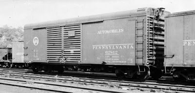
Originally, most cars of this type looked like the view below (photo from the Clark Bauer collection, location unknown). This is a car in automobile service, as we know from the white door stripes. (The word “automobiles” on the car side tells us nothing; that was the AAR description for box cars with double doors.)

But in later years these cars were replaced in automobile service. Here’s an example of what I’m aiming at for the present model, shown in a 1952 photo (Arnold Menke collection). This car no longer has any automobile racks installed, though it is likely it once did; note the tubes beneath the floor in which the tie-down chains for auto loading were stored. For more on the topics of car use and lettering, see my post about PRR wagon-top box cars (view it at: https://modelingthesp.blogspot.com/2020/11/pennsy-freight-cars-part-5-round-roof.html ).

For any particular car number a person might choose, PRR included in its ORER listing (Official Railway Equipment Register) the individual car numbers of each class, with or without auto loading racks. The car number I chose from Speedwitch set D122, PRR 60873, the same as the first prototype photo above, was a box car by 1953, that is, no longer in the automobile service for which it had been built. Here’s the  model at this point, remaining on its “interim truck support blocks” for decaling.

The next step is to add Bowser trucks of the correct PRR type, 2D-F12, with a leaf-spring snubber substituting for one spring group (Bowser no. 1-40194). I also added Kadee coupler boxes, using replacement metric screws since the model’s original ones were gone. As usual, the size that fits is 1.7 x 5 mm, 0.35 pitch. I used to buy these from NorthWest Short Line, but they are readily available all over the internet.

Finally, the model needs weathering, followed by addition of paint patches for reweigh and repack stencils, and route cards. I weathered the model with my usual acrylic-wash technique. For paint patches, I used my normal approach with rectangles of colored decal, and used reweigh data from the Speedwitch decals. A small paper rectangle represents a route card on the left-hand door.

The car is now ready to return to its owner, who I am sure will direct it immediately to auto parts service on his 1956 layout.

Tony Thompson

Tuesday, December 8, 2020

Tenth anniversary of this blog!

 Every year on December 8th, I write a kind of summary post about the history and status of the blog, because the first post to it was on December 8, 2010. That makes this the tenth anniversary! as amazing to me as it no doubt is to many others, including those who told me I wouldn’t last out the first year.

I continue to be as surprised by the size of the audience as I have been since the start. During the first three years, page views grew steadily, reaching an annual rate of about 160,000 per year. For the last six years or so, viewership has been steady at more than 200,000 views per year. The total page views since I started is now just over 1,750,000 views, a staggering number to me.

I have also been intrigued by the commentary. The total number of posts to the blog is now about 1250, and there have been more than 2000 comments posted. As has been true for some time, there are even more questions and other communications that come to me separately from the blog, usually by email. That’s fine, and I answer them all (unless it’s just a passing comment instead of a question).

I often reiterate, in these annual “anniversary” posts, that the title of the blog, “Modeling the SP,” certainly describes what I would state as my hobby goal. But many, many posts are not directly about Southern Pacific topics. I am sometimes asked, “what’s up with that?” My response is, modeling any railroad requires knowing about, and modeling, many other railroads’ equipment, and knowing about prototype railroad operations generally. Narrowly focusing on the SP would be misleading.

In that vein, I often include a favorite photo in these anniversary posts, and will again today. This one dates from about 1940, and shows an SP brakeman passing signals. I don’t know the original source, but it came to me from Clark Bauer’s collection. It does depict the work of the railroad being done, which is what I want to capture in my layout, especially in operating sessions.

For reasons I don’t know, some particular posts have held sway as the most viewed of all these 1250 posts. Undoubtedly number one is a post from back in 2013, still getting views, about canopy glue. It describes its uses and benefits, and it’s a glue I still use it for many things in the hobby. But the post keeps ticking along. If you’re interested, here is a link to that post: https://modelingthesp.blogspot.com/2013/05/a-few-words-in-praise-of-canopy-glue.html .

Number two in all-time popularity is another post on a topic I thought a minor one: duckboards. These are wooden walkways to keep people’s feet out of the mud or oil or whatever. This post continues to get views, many of them from overseas viewers, so I have wondered if this translates into something else in other languages. But here is a link if you’d like to look: https://modelingthesp.blogspot.com/2015/08/duckboards.html .

Another very early post (back in 2013) that remains very popular, I can understand better, because it describes a modeling detail that I have not seen described very often. That is the modeling of open ice hatches on refrigerator cars. It’s usually about fourth in all-time popularity, and it can be found at this link: https://modelingthesp.blogspot.com/2013/07/modeling-open-ice-hatches-on.html .

The last one I’ll mention is an “in memoriam” post I wrote about my good friend Richard Hendrickson after he passed away in June 2014. He died suddenly, and it was a real blow to me, making it fairly hard to sit down and write about him. But I often cite this post when his name comes up in email lists or elsewhere, and he was very well known in his life, so I can understand the extensive views the post still receives. It is at this link: https://modelingthesp.blogspot.com/2014/07/in-memoriam-richard-hendrickson.html .

Incidentally, in the years following Richard’s passing, I gave short talks about him to a few model railroad meetings, and included photos not used in the post just cited above. So I decided to write a further appreciation of him, including some of those additional photos along with more about his life. That follow-up post is at: https://modelingthesp.blogspot.com/2018/06/further-appreciation-of-richard.html .

With that, I’ll bring this commentary to a close. Surprised as I am to have continued for ten years of writing this blog, I guess I’m equally surprised to find I’m neither tired of it, nor thinking of stopping. I continue to enjoy sharing hobby projects and insights, and continuing to think that others can benefit from reading them.

Tony Thompson

Sunday, December 6, 2020

A better model dome platform

I have used a variety of approaches in the past to modeling dome platforms, that is, the walkways with railings that surround the expansion dome or the valve casing on tank cars. These were usually floored with wood planks until 1948, at which time steel grid became the norm with the banning of wood platforms (and running boards) for new tank cars. The photo below shows a few platforms; note how small they are, relative to the valve casings (Library of Congress photo). You can click on the image to enlarge it if you wish.


The first approach I tried was to improve, if not actually correct, the grossly oversize dome platform on the Athearn “chemical” tank car. I wrote a fairly complete blog post about this project, which you can find at this link: https://modelingthesp.blogspot.com/2014/05/upgrading-tank-car-dome-platforms.html

The net result is shown below, with the original Athearn part at right and the cut-down version at left, and though the reduced platform size is much closer to prototype, the vertical posts for the handrails are still too fat and too tall. At least I did create a wood platform surface.


     Then I tried using the Atlas part for their kaolin tank car. It has to be cut down to look like a transition-era dome platform, but certainly can be used. The description of the work I did, and the results of the effort, are here: https://modelingthesp.blogspot.com/2015/05/another-approach-to-tank-car-platforms.html . This certainly produced a right-sized and good-looking dome platform.
     But I was aware that there is an even better approach, which I want to introduce here. Yarmouth Model Works sells an etched stainless steel fret that can be folded into a very nice dome platform, kit YMW-370. You can see it on this page of their web site: http://www.yarmouthmodelworks.com/index.php/Products/YMW-370 . Below is a view of the fret as you receive it. The curving part through the center is the platform frame.

     I bought several of these kits and set about building one. Obviously the first requirement you face is having the right tools for bending etched frets like this. Some varieties of square-nose pliers can work, but by far my best results are from using “The Bug,” as it’s called, a photo-etch bending tool. It’s sold by The Small Shop ( www.thesmallshop.com ). 

“The Bug” comes with general suggestions for use. Their advice is excellent: visualize the completed part you are going to fold up. Then mentally unfold it, step by step, to make it flat. The reverse of the order you just envisioned is usually the best procedure for folding.

Although Yarmouth doesn’t offer a set of instructions for the fret itself, they do include that information in their kit for correcting a Semet-Solvay tank car. With the permission of Yarmouth’s owner, Pierre Oliver, I show below the part of that kit’s instructions which is about the fret.

“Cut the platform free from the etching sheet and ream the holes with a #78. Bend the frame in the following order. Most bends are made towards the etched fold line. A pair of square nose pliers will be very useful;
“Bend the platform support tabs.
“Bend the intermediate support legs.
“Bend the intermediate legs down.
“At the corners form the frame into a square.”

At this point it would be logical to make the platform which goes inside the frame. As mentioned, before 1948, these were wood, usually with the planks running transverse or across the car. Evergreen styrene works fine for this. Next you need to adjust the platform to fit your tank car. Here is some more of the Yarmouth directions:

“The platform railings are best formed from 6 separate pieces of 0.015” wire. 2 straight pieces for the end rails and 4 for the curved portions. The platform stanchions have thin tabs that are meant to be formed over the railings to help hold everything into place. Once all is square and parallel, secure in place with CA.”

Below is a photo from Yarmouth, showing a completed platform ready to install. You may notice that  this example has the planks running longitudinal or lengthwise on the car, which unfortunately was not the usual arrangement.

 My first project using the Yarmouth part is for a Semet-Solvay tank car, sold by InterMountain with an accurate paint scheme but lacking the prototype’s dome platform. Below is shown the folded-up Yarmouth platform frame, with its support struts arranged to contact the tank car body, simply resting on the model to show the appearance. The corner posts are not all in final position. Note that the dome walkways on either side of the expansion dome have been removed so the platform can be fitted.

The Yarmouth kit includes the new side ladders, which need to reach from the running board all the way up to the dome platform, so the ladder you see above will be replaced.

I just wanted to show how this looks in progress, and to publicize the Yarmouth part, which I think is very nice. I will come back in one or more future posts to show some completed tank cars with these dome platforms.

Tony Thompson

Thursday, December 3, 2020

Another family op session

Last summer, our granddaughter visited a couple of times for two different two-week visits, and I organized simplified operating schemes for her to do. My wife volunteered to fill out the crew. She has often been a little puzzled when four people (mostly men, some women) would show up and operate on the layout for three or four hours. I don’t mean she didn’t know what we were doing, she just wasn’t clear on whether and why it was fun.

I wrote about the sessions in the summer in previous posts. The first one, about July sessions, pointed out that at least family can participate in operating sessions even in the pandemic. That post can be found at this link: https://modelingthesp.blogspot.com/2020/07/pandemic-operating-sessions.html , while the following pair of sessions in August are here: https://modelingthesp.blogspot.com/2020/08/another-family-operating-session.html .

This Thanksgiving proved to be a long weekend, with my son bringing his daughter down on Tuesday, and staying until Sunday. There were lots of activities, but we did manage to have another operating session. As before, I just set it up for one side of the layout, this time at Shumala, and on this visit, we only had time for that one session. It would be the 57th session on the layout in its present form.

Our granddaughter is now almost nine, and is pretty experienced with an NCE throttle, so I trust her to be a more than competent engineer. She has tried being the conductor, but found the waybills a little daunting, so again this time, my wife was the conductor and planned all the moves. 

In this first photo, below, the conductor is still organizing. (You can see a number of waybills leaned up against cars in the foreground, something I don’t mind when the conductor is making sure that all the active cars have been identified, but which I discourage once the session gets underway.) The engineer is standing on a step-stool for a better view.

As the session proceeded, we did have a few snags. A coupler pulled out of a coupler box, and that car had to be set out for repairs. And a brass car happened to be temporarily stopped on a gap, and promptly shut down the DCC with the resultant short. It didn’t take long to find the source (the most recently moved car), and we proceeded.

A complex set of moves at East Shumala did challenge the crew, with two pickups and four set-outs, but they worked carefully and got it right. Here they are, comparing the agent’s message with the waybills for each of the cars identified in the message. They understood the guidance, that we weren’t in a hurry and they should take their time to understand all the moves. You can see their switcher, and its string of cars, on the main track near the layout edge, ready to go and work at East Shumala (mostly hidden behind and to the left of the crew).

The session went well, all moves called for in the set-up of waybills and car spots were carried out properly, and a good time was had by all. Can’t beat that for a holiday weekend afternoon, pandemic or no pandemic.

Tony Thompson