Showing posts with label Standards. Show all posts

Friday, December 16, 2022

Small project: upgrading couplers

 I have written several times in this blog on the topic of modeling standards, for everything from locomotives to freight cars to scenery to track and electrical aspects. My topic today happens to be couplers (for freight cars), and as everyone knows, these are essential to dependable operation (for an early statement of my ideas about standards, you could read this post: https://modelingthesp.blogspot.com/2011/03/model-freight-car-standards.html ).

A long-standing pet peeve of mine is the so-called “ready to run” or RTR freight cars with fake Kadee couplers. The Kadee patent for the No. 5 coupler ran out in the 1990s, and since then, several Chinese manufacturers have produced a “Kadee-like” design which simply falls short when operated. I can’t identify the Chinese entity behind any particular freight car, so can’t name the culprits directly. But the importers are certainly known.

The plain fact is that these couplers really do not play well with real Kadee couplers, though probably they work all right with each other. Sometimes a RTR freight car will get into layout service without my having gotten around to changing out the couplers, and inevitably that doesn’t go well.

In my most recent operating session, things mostly went quite smoothly (here’s a link to a summary: https://modelingthesp.blogspot.com/2022/12/my-fourth-2022-operating-weekend.html ), but I did have the embarrassment of discovering not one but two of these “renegade” coupler installations. Here is one example, in this case an Atlas tank car:

Anyone familiar with the Kadee design, as nearly all of us are, can immediately see that this is not the shape we all know. That is no doubt the reason for the imperfect operation. In addition, the coupler is even bigger than the oversize Kadee No. 5. At least the Atlas coupler box has a lid with a screw attachment, so it was easy to replace this thing

I might mention that with installations like this, I really have learned to prefer the Kadee whisker couplers, either No. 148 or No. 158. The off-brand couplers being replaced often have coupler boxes that are not quite the correct Kadee dimensions to use the sheet-metal spring (often a bit too narrow), so the whisker design is a better choice.

Another example is an older Walthers freight car, again with a coupler that looks like a Kadee at a cursory glance, but putting it into an operating session quickly reveals that, whatever it looks like, it sure doesn’t operate like a Kadee. Here’s a top view:

Here again, I used a whisker-style Kadee for replacement, and things then went smoothly.

I don’t want to suggest that only the two manufacturers named above are the guilty parties. Some runs of imported freight cars from InterMountain have had these sorts of fake-Kadee designs too, though thankfully not recently. I seem to recall some Broadway Limited cars in the past, also with fakes.

I suppose I should mention that the foregoing comments are entirely personal observations. I have no connection with the Kadee people other than as a satisfied customer, and an operator of pretty long standing.

I have been meaning to update my thoughts on operating standards, and these two coupler replacements (among others) have brought that intention to the forefront. I will be thinking through my current practices, and writing a post with updates, in the near future.

Tony Thompson

Friday, September 30, 2022

Ready-to-run?

 The question mark in the title of today’s post will remind older readers of previous discussions of this topic on my blog. And that stems in turn from a clinic my late friend Richard Hendrickson used to enjoy giving. He would open with a photo of a “ready-to-run” model right out of the box, shiny as anything, and then show a prototype slide of fairly new car, but of course showing signs of service. He would then put the original model shot back on screen, and dramatically exclaim, “Ready to run? I think not.”

He then went through the steps he himself used to prepare such models until they really were, in his standards, ready to run. I’ve described the same sort of process in this blog, but not recently, and in any case, my own approach has evolved a little. So I’m going to show it one more time.

I have somewhat arbitrarily chosen a new “R-T-R” model from my shelves for this project. It’s a recent InterMountain product, a 40-foot PS-1 box car. It happens to be L&N 6255, and though not “mirror glossy,” it is certainly shiny. As you can see, it has an 8-foot door, in common with new PS-1 orders by L&N totalling more than 2000 cars by the time I model, 1953. This particular car has a built date of April 1952.

My first step with a model like this is a coat of flat finish. I usually prefer the Tamiya product (their number TS-80), because of the far more dependable spray can, but do use Dull-Cote sometimes. The car has to be flatted for the next step, application of my acrylic-wash weathering process, because the water-based washes won’t “wet” a glossy surface.

Now some may comment that a new car just out of the builder’s shop would indeed be glossy. That’s true. But prototype photos of cars only a month old already show a duller finish and often a few chalk marks. If you model a specific month, as for example Richard Hendrickson modeled October 1947, then yes, a car built that month can be clean and shiny. Otherwise, I would maintain, a shiny car is a poor model.

So once the model is entirely flat, I weather just the roof, with my usual mix of acrylic tube paints (I like Liquitex), Neutral Gray, Burnt Umber, and Black. The water-base wash method is fully described in my “Reference pages,” linked at the upper right of this blog post. I might mention here that roofs got dirtier than car sides, as many prototype photos show, and I usually weather accordingly. Here is the car at this stage. It’s obvious how bright and white the unweathered lettering still is.

Why just the roof? That way, I have lots of model to hang onto while working on the roof. And in the following step, I can hang onto the model with the roof and underbody (or truck bolsters), while working on sides and ends. I have occasionally tried doing the entire car at once, but for me at least, it’s unnecessarily difficult and I often make a mess.

This might be a good place to mention trucks. Though most wheelsets coming with an R-T-R model have at least somewhat blackened wheels, they are at best semi-gloss and too pale. Moreover, the sideframes are usually jet black and glossy. Though my preliminary overcoat of flat finish mitigates the glossy sideframes, the whole truck still needs work.

I brush-paint the wheel faces with Tamiya “German Grey,” XF-63. I used to paint the axles and the insides of the wheels too, but since it’s almost impossible to see those surfaces on a layout, I no longer do that, just painting the wheel faces. While I’m at it, I usually dry-brush some of the Grey over the sideframes. The photo below shows the result. 

In this photo you can see the flat gray wheel faces, along with the coupler sides and trip pin, and a kind of highlighted gray on the sideframe. Note that the “NEW” date here is 4-52, so my modeling year of 1953 would have found this lettering still in place, along with the builder emblem next to the door. Work on the trucks isn’t finished. I will come back to them when I weather the car sides.

Next step is to weather the sides, very much like the process of doing the roof. This car is not too old, so I don’t want to make it very dirty, but do want to tone down the bright white lettering. The photo below shows the left side at this point. Note the dark splotch toward the right end of the visible side, at the top. I sometimes add things like this, which one certainly sees in occasional prototype photos, for variety.

You may also note the bulge upward in the running board, where it has come partly unglued from the roof. I have no idea what kind of adhesive is used in assembling these models, but I am confident it is not canopy glue. I simply run a razor blade under the running board from end to end to complete the “de-gluing” process, then re-glue with canopy glue. It is not only a tenacious adhesive, but remains flexible for years. Etched metal parts I canopy-glued 25 years ago are still fine.

My last step with the overall model is a coat of flat finish to protect the acrylic pigments of the weathering. Without that, a fingernail scratch can mar the acrylic layer, but flat finish is very effective in protecting it.

Finally, I add chalk marks with a white Prismacolor pencil, and add a small rectangle of white or manila-color paper to the route card board. With most models, I would also have to paint-patch areas for the reweigh and repack stencils (as I have described in this blog numerous times), but this car is so new it would not even have required a repack by the time I model. So the model is complete, as shown in this view of the right side:

I have spent the space to describe this finishing process fairly fully, just to clarify the steps I would pursue on any so-called “ready-to-run”model. My friend and mentor Richard Hendrickson was right: a model like this that you acquire is really only “ready to finish.”

Tony Thompson

Wednesday, August 10, 2022

Grumbling again about brass freight cars

 As anyone knows who operates a sizeable fleet of model freight cars, from time to time something goes wrong and a car is pulled off the layout for upgrade or repair. It may, of course, merely be a task of replacing a lost sill step or re-installing a coupler, but sometimes it is a more demanding task — and gets put off. Recently I noted that my shelf of “ailing” freight cars had grown, and set out to find what was needed to get them back in service.

It turned out that a bunch of them were brass freight cars of various origins. One of the ongoing problems with such cars can be (isn’t always) coupler box attachment provisions. Brass models often come with a set of metric screws that can secure a Kadee coupler box. That’s a simple attachment.

But not always. I recently repainted an old Precision Scale tank car, and found that the single screw hole in the coupler box pad was a very small (and missing) metric screw. I could simply have added such a screw from my own stash, but its head was too small for the hole in the Kadee box. I could have made a washer, but decided instead to simply drill out the small hole and tap it for a 2-56 screw.

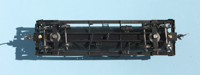
I then discovered that the frame was bent, and had to gently straighten it so that coupler boxes at both ends rode at the correct height. When all that was completed, here is the underbody (I left the coupler box screws unpainted for the photo so they would be visible). Note also that I had to add washers atop the trucks, as the car sat too low otherwise.

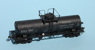
Here is the complete car, in its new SHPX paint scheme, depicting a lease to the Western Chemical Corp. of Los Angeles. It’s a nominally 8000-gallon car. Route card and placard also visible.

Another of the issues frequently encountered with brass freight cars is the annoying method of truck attachment. I’ve mentioned this in previous posts (see, for example: https://modelingthesp.blogspot.com/2012/12/small-modeling-project-brass-tank-car.html ), and also showed the solution(s) I have used, particularly replacing the truck screw that came with the model, with a metric screw of the same size (you can find that description at: https://modelingthesp.blogspot.com/2020/09/those-pesky-truck-screws-for-brass.html ).

I’ve never understood the attraction (to manufacturers) of this kind of “sprung truck screw,” unless it’s to hold trucks aligned for easy placement in display cases. It certainly does no favors for these cars in operation. At one time, I tried to find softer springs, reasoning that less force pressing the truck bolster against the car bolster should make truck swing easier. I never really got a good result, and now just snip the original springs in half (or entirely replace the shouldered original truck screws, as I described in the post that is cited in the preceding paragraph). 

But even these measures will not solve all performance issues, especially for models from what’s called the “middle age” of brass models. That usually means between the first age of durable, somewhat clunkily detailed models that operated well, ending around 1975, and today’s third age of beautifully detailed models with good quality operation — and steep prices. 

In the “middle age,” brass production seemed to be oriented exclusively to collectors, and not only collectors, but collectors who rarely if ever took the models out of boxes or display cases, and certainly never operated them. The common side effect was appalling trucks, which did look like trucks but rolled like sleds. 

Trucks like that simply have to be replaced if the models are to be operated on actual layouts. I have a few in my fleet, models of prototypes that I like to include but simply could not possibly operate with their original trucks. I put those trucks back into the original box, so that whoever acquires them someday when I’m gone and wants the original trucks, will have them with the model. 

For replacements I use a variety of trucks. If I know what trucks the prototype car had, I prefer to use a Tahoe Model Works truck of the same design, since they are accurate representations of specific trucks, roll well, and (unlike some trucks out there) have the correct height. I also have a stash of plastic truck sideframes which, with decent wheelsets, can represent a more generic “AAR truck” if needed. There are examples of both in my fleet.

As a single example, below is a W.A. Drake model of a Southern Pacific 8000-gallon tank car (dome walkway only on one side, typical SP practice). Nice, accurate model, but unlike other Drake brass tank cars I have, this one’s trucks simply could not keep the wheels all in the horizontal plane. That might be stickiness in the bolster ends, or something. But whatever it was, I just couldn’t get it to stop. Easy fix, replace those trucks. 

As should be evident from the foregoing, I expect and demand that my model freight cars operate properly. I am not collecting a display case of beautiful models; I am exercising a fleet of working freight cars in layout operations. That’s part of achieving one of my layout goals: to reproduce the SP railroading of my layout’s locale and era.

Tony Thompson

Tuesday, February 22, 2022

Improving a freight car, Part 3

 This series of posts is about describing my process for modifying or upgrading a conventional kit for a freight car to match the desired prototype (within reason) and to make the car meet my layout standards. The beginning of the work was described in the preceding post (see it at: https://modelingthesp.blogspot.com/2022/01/improving-freight-car-part-2.html ). 

(Before continuing, I can’t resist mentioning today's date, 2-22-22, a rare kind of date in any century.)

The step following the preceding post was to prepare to add all the detail parts to the car body. I always clear all the attachment holes with a #75 drill, just to make sure they are fully open. Most parts, of course, simply fit where they should fit, and no more needs be said.

This particular kit has a few extra challenges, though. The kit is made to accept a long handrail across the mid-height of the car ends, but the Southern Pacific and T&NO Class B-50-26 cars that are my prototype had no such handrail. I simply cut short lengths of the kit’s handrail, glued them into the holes provided, and cut them off flush with the surface. Biggest advantage of this method: same color material.

When all detail parts were attached to sides and ends, I glued on the replacement doors with canopy glue. Since they had been filed down in height to fit, this was a matter of just placing the doors on the car. 

I left the roof till last. I like being able to hold the body by the insides at the top while adding detail parts. Now I added the roof, and then the Kadee running board with canopy glue. The car is then ready for a coat of flat finish, followed by weathering.

Before leaving car construction, I want to mention two detail parts I very deliberately do not include. One is uncoupling levers. I know from extensive experience that these are magnets for getting snagged in operating sessions. I still have a number of freight cars with these levers, and eventually they become bent out of shape by an errant sleeve or hand, and get removed rather than replaced. Yes, of course they belong on a freight car, and if I were building a contest model, of course I would include them. But not on an operating layout.

The other detail part I deliberately exclude is the air hose and bracket. I fully realize that there are good options for sturdy versions of this part. But these too get snagged in operating sessions, and can interfere with coupler manipulation during a session. After witnessing a few such problems, I decided not to install them any longer, and have removed them for several cars. Just like the uncoupling lever, it’s a compromise for operation.

The model you see in the photo above was next given its flat finish, and then weathered with acrylic washes, in two steps: first, to weather the roof, during which the model is held by the sides; then, when that’s dry, the sides and ends, during which the model is held by the roof and underbody. 

This car is lettered as only a few years old, so I didn’t heavily weather it; but the photo below shows how much duller the body color, and the white lettering, can become, with weathering like this. Compare the photo immediately above.

Finally, I turned to the finishing steps. These involve route cards and chalk markings (for background, see: https://modelingthesp.blogspot.com/2011/11/chalk-marks-and-route-cards.html ). Actual route cards are around 4 inches square, or rectangular. I simply use very small squares or rectangles of paper, white, yellow, manila, etc. and attach with canopy glue. This photo shows the size (different model, of course). On most cars, they go on the route card board.

I also added repack stencils to this model. To do this, I add a paint square over the right-hand truck, black or boxcar red, and add repack stencil decals from Sunshine or Speedwitch. Finally, I use Prismacolor art pencils, sharpened to a good point, to make chalk markings. Here’s the finished result:

So these are the various steps I would pursue to “improve” or upgrade a typical kit for a freight car, to meet my layout standards. As mentioned, these are not “model contest standards,” just operating layout standards.

Tony Thompson

Saturday, January 29, 2022

Improving a freight car, Part 2

The previous post on this topic took up the challenge, describing what I might typically do to upgrade a car kit to my usual layout standards. The kit is an InterMountain 12-panel box car kit. You can read my preliminary analysis of needed changes and upgrades in that previous post, which is at: https://modelingthesp.blogspot.com/2021/12/improving-freight-car.html .

These particular InterMountain kits do not include car weights. I decided to use what I often use for house cars, a pair of 5/8-inch steel nuts, glued inside with canopy glue. This has proved a secure attachment, and adds close to the needed two additional ounces to meet NMRA weight standards. (I might mention that I doubt there is any great significance to the exact NMRA weight values, but I do think that consistent car weight matters in operation, so the NMRA standard is as good as any.)

I should add that before adding the weights, I drilled and tapped the bolster centers for 2-56 truck screws (discard those self-tapping screws!). This makes the screw holes evident inside the car body, and prevents gluing the weights atop them. And since the doors will be glued on, no need to paint the weights.

I mentioned in the previous post that the kit side doors were not the correct style, but that I had replacements. Here are the replacements, with the kit placard boards and route card boards in place.

I also mentioned using a Kadee Morton running board to replace the kit’s incorrect board. This has been received. But it isn’t quite the same color as the InterMountain kit parts. So both the running board and the new doors called for a paint match to the IM molded color. Like many modelers, I have a considerable stash of red-brown paint colors, of many brands. The closest match here was Tamiya “Hull Red,” no. XF-9.

The kit coupler boxes are intended to be glued in place, including box covers. I learned long ago that this is a prescription for coupler maintenance problems, so I clipped off the posts on the box covers, drilled a hole centered on the post location, and tapped both box and cover (and car body) for 2-56. This isn’t a great coupler box, and a Kadee box might be better; but I did use the kit box to install Kadee #58 couplers.

Incidentally, one advantage with making the kit coupler boxes removable, and attached with a screw, is that if any problems later develop with these boxes, they would be readily replaced with Kadee boxes. 

Lastly, in changes to kit parts, I discarded the kit’s molded plastic wheelsets intended for the trucks — this type of wheel has long been banned from my operating equipment — and replaced them with InterMountain Code 88 wheelsets. These metal wheelsets look better, run better, and don’t collect dirt.

I should mention that although these InterMountain trucks resemble the ASF A-3 trucks actually applied to the prototype cars, they are not quite an A-3, but I decided to use them, since they are close. For a great deal more on this point, you may wish to consult Richard Hendrickson’s 2014 article on model trucks (there’s a link at: http://modelingthesp.blogspot.com/2013/07/another-update-to-richard-hendricksons.html ).

With these modifications, I was ready to proceed with the more mundane aspects of the kit assembly, most of which I won’t bother to describe, but will then carry out weathering and other finishing details. Those will be described in a future post.

Tony Thompson


Tuesday, July 20, 2021

Layout evaluation

 I know that the subject line for this post could mean many things. But I’m referring to my own layout, and to an evaluation I was asked to make, as a member of a discussion panel about layouts, on “Lessons Learned.” This took place as part of the recent NMRA National Convention, nominally hosted in Santa Clara, California, but in fact entirely virtual. The discussion panel was one of many virtual events that was held.

The layout owners on this panel were asked to identify the features of their layouts that were “good,” meaning turned out as planned or were good features that just developed. Also requested, of course, was identification of mistakes or well-intentioned features that simply did not work out. This seemingly simple charge soon proved, to me at least, to be rather more thought-provoking than it seemed at first glance.

I should begin with the layout itself. As experienced readers of this blog will know, my layout is T-shaped, with the two legs of the “T” each about 15 feet long. It is essentially located as a peninsula in the room (the vertical leg of the T), with a cross-piece along the far wall of the room. Here is an overview of most of the layout, looking up the peninsula:

Several things are evident in this photo, that I deliberately chose as features, and that I think are among the successful aspects of the layout. First, aisles on each side are wide, 3 feet at left and almost 4 feet at right. I have operated (and still operate) on layouts with much narrower aisles, and believe me, I like this much better. Second, the large hill at the end nearest the camera acts as a view block to keep the two sides of the “T” visually independent (the photo is taken standing on a stool — this is not a view a visitor would get unless 7 feet tall). 

Third, my previous layout had 2 percent grades, uncompensated, to and from staging located on a lower level. I resolved to keep the entire main line, including staging, perfectly level in the present layout. I did accomplish that, and have been glad ever since that I did.

It’s a minor fourth point, but it turned out that the end wall in the photo above is an excellent location for the layout clock, visible from every operating position. This isn’t a fast clock, it runs at 1:1, but it permits “layout time” to be the part of the prototype Guadalupe Subdivision timetable in which I want to operate. (I have posted several discussions about fast clocks and my use of the clock seen above; for an introduction, you might like to read this one: https://modelingthesp.blogspot.com/2017/12/fast-clocks.html ). And I will mention in passing a kind of fifth point, that adoption of DCC considerably simplified some aspects of layout wiring, but that wasn’t a design choice.

My sixth and last point about things going as well or better than I planned is the amount(s) of switching in the three towns on the layout. I do proportion the work in each town when I set up an operating session, but generally operators have found the amount of work to be about right. Below is a snapshot of SP 2829 backing across Nipomo Street at Ballard, in the midst of switching. In the background can be seen six of the industries here.

What about things that haven’t been so satisfactory, either design errors or defects that have evolved over time? Well, there are some of both. One of these was a choice of convenience, to re-use the backdrop created for the layout when it was set on the Pacific Coast east of Surf, with high hills right behind the SP tracks at what was then called Jalama (Shumala on the present layout). But Shumala is set a little south of Oceano, and though there are hills in the distance there, they aren’t like my backdrop. Well, most people don’t know that, and I guess I will continue to live with it.

I did learn something from that backdrop issue, and have made the backdrop on the new part of the layout, at the end of the branch at Santa Rosalia, on the Pacific Ocean shore, accurately displaying the view you would get looking southward along that shore. In this view, you can also see the bill boxes on the shelf under Santa Rosalia, for both the towns of Ballard and Santa Rosalia. There is still one industry to be built here, but most everything else is completed.

Another point which has occasioned a lot of comment from visitors is my staging arrangement, basically a transfer table. I got this idea from John Signor, who has a 16-foot one on his layout, and his operates flawlessly. But unfortunately I ignored John’s advice on building it. He had a local cabinetmaker build his, and it is beautifully solid and square. Mine is only 7 feet long, so I thought, “Heck, I can build that with plywood and 1 x 4s.” I was right that I could, but wrong that it would perform anything like John’s professional version.

I was a little surprised how interesting it turned out to be, to step back and assess the layout from a wider perspective. On balance, my feeling is that the layout has turned out well, very much the kind of thing I wanted to accomplish when I started on this version, now about 12 years ago. None of the things I regret, or have realized should have been better, have been serious drawbacks, and I suppose you can hardly wish for more than that.

Tony Thompson

Tuesday, May 25, 2021

Passenger car diaphragms, Part 2

 In my previous post, I introduced the topic of modeling passenger car diaphragms, starting with older cars like heavyweight Pullmans. I showed both the prototype appearance, and the old Walthers diaphragm parts for HO scale. (The post can be found here: https://modelingthesp.blogspot.com/2021/05/modeling-passenger-car-diaphragms.html .) In the present post, I want to continue with this topic.

First, I mentioned in that previous post that the Walthers diaphragm, though perhaps useful in filling large intercar spacings, is really too big for realistic spacings. It is easy to correct, as I pointed out; one fold or two folds can be removed, as desired (more on the criteria for doing so in a moment). Shown below is my 12-1 Pullman, Columbia Glacier, with a shortened Walthers diaphragm. This car, for those interested, has previously been described (see this post: https://modelingthesp.blogspot.com/2014/07/modeling-sp-passenger-cars-heavyweight.html ).

You may be able to tell, in the above photo, that the face of the diaphragm is about at the inner side of the opening in the coupler beneath it. This is my usual criterion for diaphragm depth. You can see it more clearly below. This geometry allows good performance on curved track, while maintaining near-contact of diaphragms on straight track, perhaps the best compromise.

I should repeat a comment from the previous post (link in top paragraph, above), that in later years head-end cars often lost most or all of the canvas bellows in their diaphragms, leaving the striker plate and not much else. To illustrate, shown below is a detail from a Wilbur C. Whittaker photo of SP 6188, a Class 60-B-2 car at Oakland on April 13, 1951.

In model form, this is fairly easy to duplicate; I showed my modeling of these minimal diaphragms in a previous post (that post is at this link: https://modelingthesp.blogspot.com/2014/06/modeling-sp-passenger-cars-part-5.html ). That same post shows my face plate drawing for making new styrene face plates. It also referenced my kitbash of an SP 70-foot baggage car with side windows, for a car that retained the top spring bar and a side fold of a bellows. You can see the diaphragm on that model below, with the top spring element visible.

Brass models of SP head-end cars have sometimes included these simplified diaphragm representations. Below is a photo of a Precision Scale Class B-60-10 car in HO brass; coupler is removed for clarity.

None of these models, in either this or the previous post in the series, include stabilizer rods. I will take up that topic in the next post in this series.

Tony Thompson

Friday, May 22, 2020

Healing the sick

No, no, it’s not another coronavirus post. I’m referring to sick freight cars. Anyone who operates his or her models, either personally or in operating sessions, will occasionally find defects arising in car performance. A previously correct coupler height may have drooped; a coupler may have lost its knuckle spring; something on a car has begun to interfere with truck swing; and so forth. Note I’m describing defects that can arise over time. Obviously these and other defects, if present, should have been corrected before a car was put into service.
     Now it’s true that most people with operating layouts will have developed some sort of “bad order slip” to report defects. I have had various versions of such a form for years. When something acts up in car performance, I (or a visiting operator) usually fill out a slip. And often these slips remain with the car until it gets corrected. But note the words “usually” and “often.” No further emphasis needed.
     With our current “stay at home” circumstances, and working around the layout and my two workbenches quite a bit, I became aware that there are a substantial number of “sick” freight cars here and there, naturally no longer with companion bad-order slips (if they ever had them). Otherwise, of course, they would have been repaired long ago (uh-huh). So it was time to dig into this mini-fleet and get corrections made.


Above you see one part of this fleet of “sick” cars, and it may be obvious that there are no bad-order slips visible.  Here’s another example:


A few of these are construction projects, but most are out-of-service cars needing work.
     How to approach this problem? The first step is to re-check the “freight car standards,” along the lines I have outlined in previous posts (for one example, see this post: http://modelingthesp.blogspot.com/2011/03/model-freight-car-standards.html ). This means the performance part of the standards described in that post: trucks and couplers.
     I have written previously in some detail about exactly how couplers have to perform (that post is at: https://modelingthesp.blogspot.com/2019/10/maintaining-model-couplers.html ). My test set-up has two Kadee gauges on a length of track, with an Atlas re-railer in the center to make it easy to put cars on to test, all attached to a wood strip (this was designed and built years ago as a gift by Jim Ruffing).


     Trucks likewise have to be carefully checked, and I included that as one part of my  “rookie test,” a procedure I described earlier (view it here: https://modelingthesp.blogspot.com/2018/07/the-rookie-test.html ). In many cases, at this point I have already discovered what was wrong with a “sick” car. But not always. A way to check further is a switching test.
     Nowadays a challenging switching test, intentionally more challenging than normal operation, has become part of my rookie test. I described it in a prior post (that post is here: https://modelingthesp.blogspot.com/2019/06/rolling-stock-upkeep.html ). Here is a repeat overhead view, of the sequence of track switches, through which I push and pull strings of cars at various speeds, up to pretty high speeds, even up to the locomotive maximum. This does identify cars with stubborn performance problems.


The diverging legs of the two #5 turnouts at photo center are preceded (out of view at left) by the curved part of a #6 switch. Any tendency for truck swing or performance to cause a derailment surfaces quickly in this test (and sometimes couples with inadequate range of swing can do so too).
     For the present effort to “heal” more of my backlog of out-of-service cars, I made up a table to be filled out (the form of the table is shown below, though the one I actually use is hand written). The first column is coupler swing and knuckle action, the second is coupler and trip pin height, the third is truck swing and tram, and the fourth, freedom of wheelset rotation in sideframes. Then the fifth is that switching test through chained turnouts (see last post cited in previous paragraph), sometimes followed by a sixth: tests of switching in a couple of different layout industry spurs that involve grades into the spur or other challenges.


In the sample table above, the first two cars have passed all tests and many not need to be subjected to the test listed in the final column. The lower three cars were still in process of testing at the moment shown for this table.
     It has been satisfying to dig into the backlog of “sick” cars that had stealthily grown way too big, thus to clear cars to return to service, and interesting in making sure I am systematic about the testing, and that I can keep the test records for any of these cars, should they act up in the future. And one of these days, these cars will be available when we have operating sessions again!
Tony Thompson

Monday, December 16, 2019

Prototype lettering, Part 2

I have long spoken up about accuracy in model lettering, using as a standard, what else, the prototype. Among  my explorations of this topic is this one: https://modelingthesp.blogspot.com/2019/04/small-rant-manufacturer-lettering.html . That is part of the background to the first post in the present series, Part 1, which showed several examples of stencil lettering practice (you can see it at: https://modelingthesp.blogspot.com/2019/12/prototype-freight-car-lettering.html ).
     Continuing in the same vein, Southern Pacific used stencils for entire words in lettering in later years, for example after 1946, when the initials “SP” were replaced as the reporting mark by the spelled-out road name. Here is an example of the process, with a spray gun being used (SP photo, negative 30630, CSRM).


Note against the car door another of those “half ladders” used for decades by SP painters.
     Another point, mentioned in the previous post, was the widespread use of what was called “stencil paste,” not a liquid paint but a semi-solid material, applied with a short, stiff brush. An example of that use is the photo below, which depicts a workman applying reweigh data by hand, using individual number stencils. Obviously such application did not always result in perfectly aligned and spaced characters.


     At this point, I want to mention something raised previously(see the first post cited in the paragraph at the top of the present post). Nearly all railroads used lettering characters they had designed themselves. Someone on the drafting room drew up a set of letters and numbers, and such a drawing was the basis for making stencils. Naturally this meant that a separate drawing had to be made for every height of letter, from 1, 2 and 3 inches up to 9 inches or more. It is always intriguing to compare the letters of different sizes. Invariably, the thinner parts of each letter are much lighter in the large sizes.
     There has long been, among modelers, a belief in a kind of lettering usually called “Railroad Roman,” and decal sets have been so identified for decades. There is in principle a possible prototype for this, because early in the 20th century, the Master Car Builders suggested a "standard letter," and this was sustained by the ARA and later the AAR. The catch is that no railroad of which I’m aware followed it entirely, though a few (CB&Q comes to mind) did use parts of the AAR alphabet.
     To show what I mean, below is presented the AAR characters, and below them, the actual SP 4-inch letter drawings for each letter and number in the AAR set. You can readily see that they do not match, with the SP numerals in particular being distinctly more condensed than the AAR numerals.


     To conclude, I show the SP lettering process of later decades, now with the workman wearing protective gear, but still using single-character stencils. There is a least a chalk line to guide the application. This was taken at Sacramento General Shop (SP photo).


     Being aware of these processes helps guide us as modelers in how we apply lettering to models, and tells us where we can permit irregularities in lettering, and where it really has to be done right. I will return to this topic in a future post about modeling.
Tony Thompson

Sunday, October 20, 2019

Maintaining model couplers

I have posted comments from time to time in this blog about the various needs for maintenance of freight cars to make sure they operate as they should. This is potentially a really wide-ranging topic. Probably the broadest recent post like this addressed several kinds of maintenance issues (you can read the post at this link: https://modelingthesp.blogspot.com/2019/06/rolling-stock-upkeep.html ).
     My recent experience with the operating weekend at VanRail in Vancouver, British Columbia showed me some compelling examples of how well this can work. (For an overview of that event, you may wish to read the post about it, which is at: https://modelingthesp.blogspot.com/2019/09/vanrail-2019.html .)
     In particular, I was struck by the good operation at Mike Chandler’s layout, because he uses Kadee magnetic uncoupling ramps, often in layout locations that you really cannot comfortably reach from the aisle. This means that couplers must operate flawlessly, and they did. I came away with the determination to re-examine my own fleet and try to correct any couplers that are off in height or were even a little bit sticky or not free-swinging.
     Shown below is an example of couplers that almost line up perfectly, the one on the right being a Kadee #5. But even though a coupler pair like this will work fine on the main line, it many not behave as desired in tight switching locations, or in the presence of any trackwork shortcomings.


Below is a second example, this time showing two cars with #58 couplers, but here they are matching perfectly and accordingly will operate all right. It’s always best to strive for complete height matching, and I am working on my fleet to get there.


The cars above are a Westerfield AC&F reefer at left, and an InterMountain SP covered hopper at right.
     Coupler height is most easily adjusted with washers at the truck bolster, and that is what I usually do to make cars match the Kadee gauge as exactly as I can. (I have written about use of the Kadee gauge before, partly because I am surprised when modelers tell me they don’t even have one; for example, the post at: https://modelingthesp.blogspot.com/2018/07/the-rookie-test.html ). In my opinion, you simply cannot compromise on coupler height.
     Let me add some specifics having to do with the mixture of Kadee #5 and #58 couplers, like I have on my layout. I have said several times that I find that these operate very well together, provided that they are operating properly and that one recognizes the simple fact that the scale-head coupler necessarily has less gathering range and is less forgiving on vertical curves. But how about using the Kadee coupler gauge with mixed couplers?
     I contacted Sam Clarke at Kadee to ask him about this point, because I was uncertain how I should use the gauge with two different couplers such as the #5 and #58. He began by pointing out that the definition of coupler height is from the top of the rail to the centerline of the coupler. The Kadee couplers have a horizontal mold parting line that can be discerned on the coupler face (and on the coupler horn at bottom in this image), that locates this line for you.


     Sam went on to say that the best way to set coupler height is with the coupler center lines matching, such as  with the #5 and #58 combinations. But because they are close, he suggested that matching the top surfaces of the two couplers should also be okay, as long as you are consistent.
     One other point. Especially on the layout, you may need to search a little bit for good background to evaluate your couplers when gauging them. The photo below illustrates a less than terrific choice, using my old Kadee 205 gauge (there is a new 206 plastic gauge).


Putting a piece of white paper behind the gauge and car makes it far easier to see clearly what you are evaluating (the same is true, of course, at the workbench). Note also that the trip pin correctly clears the “shelf” at the bottom of the Kadee gauge.


     One last point: you will note above that the cars are not coupled to the gauge. Coupling them may lift one coupler relative to its rest position, so you need to move the car close to, but not coupled to, the Kadee gauge.
     I am working through my car fleet, a few cars every time I get the impulse, to set coupler heights to the gauge, and of course keeping notes as to which cars have been done. It might be an ongoing project you would like to attack also.
Tony Thompson

Monday, September 23, 2019

Fixing fragile sill steps

Most of us are familiar with the fragility of styrene sill steps on freight cars, and even when tougher engineering plastics are used for these parts, they simply are not really durable. Now, a person who builds models for a display case, or who only operates his layout himself, may not break very many of these steps, but a layout that has various populations of visiting operators from time to time will certainly break a fair number.
     Before saying more, I should credit my late friend Richard Hendrickson, who insisted that the first thing one should do with a “ready-to-run” (RTR) freight car — which he always referred to as “ready-to-finish” — was to slice off those fragile sill steps, and replace with sturdy metal, such as A-Line bronze steps. So in this context, when I say “fix” the steps, I really mean “replace.”
     Alas, I am not so meticulous or rigorous as was Richard, and I must confess that often I have put new RTR freight cars into service (after weathering, which was Richard’s second step). It’s only occasionally that I take the trouble to replace sill steps before operating a car.
     But naturally in due time, in the course of multiple operating sessions, the original sill steps do break. On the prototype, a missing sill step would be immediate cause to direct a car to the repair track, but I may wait until two or more steps are missing before sending the car to the workbench.
     Once there, cars may accumulate until I am in that “fix the darn steps!” mood, and then I undertake a whole batch of cars with the same repair need. I’ve described my technique in this blog previously, but will repeat part of it here, while showing another feature of my approach.
     Because I find I don’t have the accurate drilling ability to drill into and parallel to the car side, thus locating new steps right where the old ones were, I begin instead by gluing styrene blocks behind the sill to serve as backing. I usually use HO-scale 4 x 4-inch styrene for this, cut to fit the length of the new sill step. Here is how it may look at this stage.


     Then I drill into the styrene block, or between the block and the car side, with an appropriate-size drill in a pin vise. For most freight cars, this drilled hole will reach all the way into the car interior, which is helpful for steps with long attachment pins. Usually I then put a little CA onto the step and slide into the holes, or, if not confident of the smoothness of installation, I install the steps, then add a drop of CA at the surface, to wick into the hole and complete the joint.
     For the car you saw in the photo above, I decided to use some of my stash of Tuttle Industries sill steps, a marvelous product that unfortunately did not survive long in the market. These are so-called “Style B” steps, meaning the leg toward the car center is angled. This is written on the package label.


     These have a great looking cross-section and nice, sharp corners, unlike A-Line steps, though I will admit that when painted a dark color, such as boxcar red or Pullman green, details like corner shape are hard to appreciate. But on some cars, I do like to use the better steps. Here are two of the Tuttle steps, just having been inserted into the styrene blocks as described above.


The completed car, with steps unpainted so they will show up better, looks like this (it’s a Proto2000 model, quite close to the Southern Pacific’s Class A-50-14). You may wish to enlarge the image by clicking on it.


     I don’t wish to give the impression I don’t like or don’t use A-Line steps. I certainly do, by the dozen. Here is just one recent example, again unpainted, on a PFE express car. It’s an InterMountain model, with trucks modified to represent the Chrysler trucks used on 25 of these conversions of Class R-40-10 reefers (for more, see my post about creating these trucks: https://modelingthesp.blogspot.com/2016/02/pfe-40-foot-express-cars-part-2-trucks.html ).


     As I see it, this kind of step replacement (really, step upgrade) is a necessary part of maintaining the layout car fleet. Occasional damage such as the loss of a sill step, is a small negative, when measured against the fun of operating sessions, and in any event, the resulting repairs are not difficult.
Tony Thompson

Saturday, June 29, 2019

Comments on truck maintenance

By “truck maintenance,” I primarily mean correcting any deficiency in how an in-service model freight car truck operates, but it may be almost as important to recognize the need to get new trucks into suitable operating condition. That could then become part of what I’ve called a “rookie test.”
     I have posted several comments about my concept of a “rookie test,” meaning the testing I do with new freight cars entering service. The components are obvious things like freedom of truck swing, coupler centering, coupler height, trip pin clearance, and coupler knuckle spring operation. That test and some ways I implement it were described in the first of these posts (see it at: https://modelingthesp.blogspot.com/2018/07/the-rookie-test.html ).
     I have expanded on the original description of my rookie test in a couple of places. Perhaps the most relevant to the present post is at this link: https://modelingthesp.blogspot.com/2019/06/rolling-stock-upkeep.html . I’ll show a photo similar to one from that post to show an important part of my car testing:


What you see in the lower part of this “aerial” view of Shumala on my layout is a test train, backing through the reverse or diverging side of three turnouts, two of them no. 5.
     This test has become an important part of what I now do as part of a rookie test or else a “return-to-service test.” I couple up a string of cars, some that are being tested, along with some already qualified, and use a locomotive to run them back and forth through a sequence of the diverging sides of turnouts, at slow speed and then at faster speeds, to see if they behave. And when that test goes all right, I rearrange the car order and repeat, and then maybe create a third or fourth ordering of the cars and continue testing.
     What has caused me a certain amount of heartburn is that freight cars that easily pass the normal rookie test may not consistently pass the test shown in the photo above. Yet they are consistent in another sense, in that they continue to pass the rookie test. The question becomes, why can’t they pass this “running test?” Repeated examination of cars, and repeated testing (I am giving a short version of this, believe me) has shown that the problem almost always lies in the trucks.
     The truck problems are usually one of two issues. First, the truck molding may be a little warped, so that all four axle ends are not in the same plane. This tends to raise one wheel a little, and over curved track, especially turnouts, this drives derailments. You can detect this if all four wheels do not sit flat on a surface, but do this with the truck both right side up, and upside down, because the axle-end hole in the truck is bigger than the axle end.
     I have tried heating up warped truck moldings in very hot water and trying to bend into correct shape, but this nearly always fails. A truck like this just has to be replaced.
     The second problem that I have seen is when one of the axles in a truck doesn’t roll as freely as the other, and I mean a big difference. This may also arise from a somewhat flawed original molding. My test is to spin each wheelset and see how freely (and how long) it spins. It looks a little like this:


     Usually all four wheelsets in the two trucks are the same. But not always. When one wheelset doesn’t roll freely in curved track, where the two ends of the wheelset have to travel different distances, this too can facilitate a derailment. I have tried “cleaning out” the journal hole in such trucks, which rarely helps. Usually the dimensions are at fault, and a wheelset that is shorter will fix the problem.
     An example recently was a truck with wheelsets with 1.015-inch axle lengths. Three of the wheelsets worked fine, and spun freely in the journals. But one of them would hardly even rotate. Experimentation showed that in that journal pair, only a Reboxx wheelset, of 1.000-inch length, would work. With all four axles now spinning freely, the truck worked fine.
     This of course is the great advantage of Reboxx wheelsets: they come in a range of lengths, and I have been surprised how widely the journal width of commercial trucks varies. I have improved many poorly performing trucks, just by replacing the wheels with proper-length Reboxx wheelsets (you can visit their site at: https://www.reboxx.com/wheelsets.htm ).
     Wheelsets over the years have been taken for granted, in the sense that we expect them to fit any truck we happen to pick up. But of course experience will soon teach that it just isn’t so. A wheelset that runs freely and smoothly in Truck A may hardly rotate in Truck B, and might be so short as to almost fall out of Truck C with no urging. I happen to like the Kadee Code 88 replacement wheelsets, and have used a lot of them in various trucks. But though Kadee doesn’t tell you so, their length over axle tips is 1.020 inches. That’s fine in many trucks, but too long for others. Again, Reboxx supplies an answer to this.
     Some readers at this point may be muttering, “Why don’t you just replace the entire truck and be done with it?” and sometimes that is indeed the only solution. But if the truck has a sideframe design you can’t readily duplicate, and it’s correct for the freight car in question, you need to try and save the truck. Or if the truck mounting boss on the freight car is not friendly to any other truck design, you just have to figure how to make that bad truck work.
     Incidentally, I should mention that I wrote a related post recently, entitled “Improving Model Freight Car Trucks” about primarily improving the appearance of model trucks, but the present post is more about the operational quality of trucks.  (If interested in the previous one, here is a link: https://modelingthesp.blogspot.com/2019/06/improving-model-freight-car-trucks.html .)
     So even though my rookie test reveals lots of problems with freight car operation, issues in the trucks can be too subtle to be entirely visible that way. More analysis, of the kind described in this post, may be necessary in addition.
Tony Thompson
    

Friday, February 22, 2019

Powering turnouts

I have a general standard as to how turnouts are thrown on my layout. I want them to be hand-thrown wherever possible. Most of my layout is a branch line, and certainly turnouts on such trackage were hand-thrown on the prototype. Even switches on the segment of the Coast Division main line that I model would have been hand-thrown in my modeling year of 1953.
     But sometimes one may not wish to use a “standard” hobby ground throw. I have mentioned previously that I dislike the immense and out-of-scale size of Caboose Industries ground throws, and have replaced them with Bitter Creek ground throws wherever possible. (see for example my post at: https://modelingthesp.blogspot.com/2017/03/choosing-ground-throws.html ). But there are still times when I don’t want visitors to have to reach too far into the layout to throw a switch.
     I haven’t described it anywhere in this blog (and perhaps I should), but I have built rodding for two mechanically operated turnouts, engaged by push-pull handles at the layout fascia. This approach works well when you  have a straight line, perpendicular to the track, that reaches the layout edge. Here is how that fascia area looks:


The two push-pins you see are the handles for push-pull controls for turnouts in the back part of this area of the layout. They are recessed into the fascia so as not to be accidentally bumped or bent.
     But sometimes layout geometry can fight you on this idea. That is my situation at the part of my layout where the town of Ballard transitions to Santa Rosalia, and track makes a 90-degree bend. Rigging manual throws such as shown above in that inside corner really is not workable; operating rods all converge in one area. Moreover, there is limited clearance under parts of that area, due to staging and other things beneath.
     Those problems rule out the very nice Blue Point device, marketed by A-Line, which is an excellent design but a little too big for this location. And as I mentioned, the layout geometry at this corner works against a straight-line manual operating rod.
     Originally in this area, I decided to use some old twin-coil switch machines that I had retained from my layout in Pittsburgh, back in the 1990s. In a previous post, I showed how I concealed one such machine (see it at: https://modelingthesp.blogspot.com/2015/05/constructing-section-buildings-part-2.html ). The Kemtron machine I installed was old when I installed it in Pittsburgh, and by now it was really old.
     These twin-coil switch machines are totally reliable in my experience, and the power routing they provide with their auxiliary contacts is effective. But they do throw with a loud “clack,” and the switch throws very fast. Not really the best combination of characteristics.
     Stall-motor switch machines have been around for decades. I successfully used an Electroplumbing machine from American Switch & Signal on my layout in Pittsburgh. More recently the Tortoise machine (produced and sold by Circuitron) has become almost ubiquitous on North American layouts. But the Tortoise is a pretty big device, and wouldn’t fit under the layout area in question.
     I decided to try some of the newer servo-type switch motors, like the ones sold by Model Railroad Control Systems. (See their product description at: http://www.modelrailroadcontrolsystems.com/mp1-version-2-switch-motor/ which includes ordering capability, and, if you like, view also the manufacturer’s product brochure [made by a company called MTB in the Czech Republic] at: http://www.modelrailroadcontrolsystems.com/content/MP1%20brochure.pdf ). Here is what it looks like. The contacts in the green area are the wiring connections. The red part is the slider that moves the throw bar of the turnout. The whole device is only 1.5 inches square and less than 3/4-inch tall.


This machine is not a stall motor, but has limit switches that turn off the motor when a preset movement limit is reached. You can choose the amount of throw; I found the 3 mm setting to work fine on HO scale turnouts. 
     I installed one of these motors right where the Kemtron twin-coil used to be. Here is a view of it in place, with both the power wires for the motor, and the auxiliary wiring for track power to the frog, all installed. I have a simple SPDT switch to control this motor.


The wiring coming from two sides is derived from the locations of connections to the prior twin-coil machine and are not optimum for the MP1, but they work. And by the way, this machine doesn’t have to be surface mounted; it works equally well mounted under the layout. This one just happens to be in an area where under-layout mounting would be a challenge.
     The switch motor, of course, is not exposed like the above photo when the layout is being operated, but as was arranged for the twin-coil before it, resides inside a maintenance building:


     I will use this motor as part of an upcoming operating session, and will see how it performs. But in my own testing, it seems fine, and its advantages of small size, easy surface mounting, and convenient wiring connections seem good to me.
Tony Thompson