Monday, December 30, 2024

Those high brake wheels

Not long ago I received an interesting question at an operating session on someone else’s layout. One of the visitors came up to me and asked, with a smile, “You’re a freight car guy, right?” As long-time readers of this blog will know, that is indeed something I’ve been called before. (You can read some background at this link: https://modelingthesp.blogspot.com/2019/10/whats-freight-car-guy.html .) 

When I acknowledged that I was such a guy, he posed his question: “How did brakemen operate those vertical-staff handbrakes with the wheels close to the roof?” What he meant, I believe, is shown below on a model of one of Southern Pacific’s temporary cabooses, converted from a box car, shown on the caboose track in my layout town of Shumala.

I began my answer by going back to the early history, when such brake staffs were a lot longer, intended for men working on the roof itself. As an example, below is an Ensign company photo (Cyril Durrenberger collection) of T&NO 1192, a car built in 1888, showing its B end. The grab iron row in this case is at the left edge of the end (about as many cars had them on the right edge), and clearly there is no brake step. A brakeman might have to operate this from the roof. 

(The photo above, and the car photos below, can be found in my book “Box Cars,” Volume 4 in the series, Southern Pacific Freight Cars, Signature Press, 2nd edition, 2014). Below is a famous illustration from the 19th century, dramatically showing men applying handbrakes in a snowstorm.

As the illustration shows, at that time, before air brakes, brakemen had to move along the roofs of cars, setting the brakes by hand. This was perilous and obviously could and did lead to injury or death. I should emphasize, however, that at least as early as 1869, some cars did have brake steps, as shown in the Promontory, Utah view below (detail of A.J. Russell photo, Oakland Museum). It was up to the car buyer to make this choice in those days. Note that the brake staff and the grab irons are on the right.

By the end of the 19th century, it became common (and later was required) to provide a step on the car end, for a brakeman to use when setting hand brakes. The brake location on the left of the car center line also became standard. But as you see in the 1902 photo below (Steve Peery collection), the grab iron row might not be there at all, and brakemen had to use the grab irons on the car side.

It wasn’t until the Third Safety Appliance Act of 1910 that mandatory locations of safety appliances came into being (previous Acts were in 1893 and 1903). The photo below is on the hump at SP’s Taylor Yard in Los Angeles (SP photo). This clearly shows how a brakeman operated the hand brake with the wheel close to the roof surface.

This arrangement continued on house cars as long as there were vertical-staff hand brakes. But starting in the late 1920s, geared hand brakes became more and more common. This provided a considerable mechanical advantage for the brakeman applying the hand brake. The brake wheel was then attached to a gearbox, and thus had a horizontal instead of a vertical shaft. It was operated from not too different a position than shown in the photo above; this image is from a Cyclopedia advertisement.

One message from these photos is that the brake step was a very important part of a freight car for brakemen. After 1966, it was moved much lower on the car side, thereby avoiding the obvious risk of having to work at the car’s top. But the method of operation remained quite similar.

So those vertical-staff hand brakes, for any time substantially into the 20th century, should not be too tall, and of course should have a brake step. Brakemen certainly counted on the brake step when they had to apply hand brakes with that equipment.

Tony Thompson

Friday, December 27, 2024

Refining scenery, Part 3

Back in the summer of 2024, I relocated the MP1 switch machines at the throat of my trackage into the layout town of Santa Rosalia. I won’t go into the reasons for that (it can all be found in a series of previous posts, culminating in this one: https://modelingthesp.blogspot.com/2024/07/update-on-switch-machine-installations.html ), but to sum up, the relocated machines had linkage exposed between machines and track. This can be seen below, along with remnants of previous arrangements. 

The “trenches” in which the linkages lie need to be filled in with paper mache, so they can be scenicked. The wire linkages pass through brass tubing, so filling the “trench” will only contact the tubing, and allow free movement of the linkage wire. In addition, the surrounding area was unfinished scenically, so that needed attention also. Below is an older photo of the entire area, as it appeared when the current structures were in place and the MP1 machines connections were concealed.

The building at photo center with the gray roof, built from a Timberline kit, is called “Ballard Farm Supply,”and is located here to cover the switch machines shown in the upper photo. To its right is a railroad water tank, and in the foreground is the Richfield bulk oil dealer in the town of Santa Rosalia, including a tank car spotted for unloading.

I applied Sculptamold paper mache to the linkage trenches, and also to make some ground contours in the area. As you can see below, this area is right in front of the backdrop, and some effort is needed to minimize visibility of the joint between horizontal layout surface and vertical backdrop. The loading dock in the photo below shows the location of the left end of the Ballard Farm Supply building.

Next the area needed to be painted. I used acrylic tube paint in Raw Umber for this. I extended the color over the entire area, since I want to scenick it all.

Next I applied my usual technique, a coating of matte medium followed by real dirt and a few pinches of Woodland Scenics grass. Then the area is spritzed with “wet water” to make sure the matte medium contacts all the scenic materials and secures them.

Finally, to show how this was supposed to end up, I show below the Ballard Farm Supply building in place to conceal the MP1 machines, though with its roof off. Other scenery work in the area remains to be done. Incidentally, the Farm Supply business does receive inbound rail shipments, but having no spur of its own, receives them at the town team track.

As I have observed in each of these “Refining Scenery” posts, this is a quite minor project, but I wanted to show it to illustrate the kind of thing that is often needed, even on a layout as nearly complete as mine. More later.

Tony Thompson

Tuesday, December 24, 2024

More crate and box loads, Part 2

In a recent post, I showed how I made use of some hardwood offcuts that were mostly but not entirely square, to make shipping box or crate loads suitable for gondolas or flat cars. I showed one of them loaded in a gondola. But more needed to be done on this project: the third of the three loads hadn’t been finished. To read that previous post, see this link: https://modelingthesp.blogspot.com/2024/11/more-about-making-crate-and-box-loads.html .

The first additional task to describe is finishing the third and largest of the three loads. As was described for the the other two crates, in the previous post (link above), it was made to “sit square” by adding a styrene support underneath to level it. Then scale 1 x 10-inch styrene strip was glued to the bottom of the sides to conceal the angled cut on that part, and likewise around the top, using canopy glue. Finally, a piece of sheet styrene was glued to the top, since its end grain simply couldn’t be adequately concealed with modeler’s putty.

As a reminder, this box is 1.25 inches high and1.5 inches long. Some of the sanded areas of putty can be seen above as lighter areas. Then the crate was painted again, using the same Tamiya “Haze Grey” (TS-32) as before.

Another feature that needs to be present on such a load is a means of securing the crate to the freight car. In later years, steel banding was very widely used for this purpose, but at the time I model, 1953, only some photographs show banding used to secure this kind of a load. For crates like these, a common hold-down method was lengths of timber that could be spiked or lag-screwed down to the wood car deck of the flat car or gondola, and also bolted to the crate. In HO scale, I usually use scale 6 x 6-inch stripwood.

Lastly, labeling matters too. No doubt there were unmarked crates and boxes shipped like this, but marked ones are not only more interesting, but they add to the information in the accompanying waybill. I show two examples below. One is the familiar electrical equipment distributor, Graybar, at that time headquartered in Chicago. The other is a Naval Supply Depot, which would ship materials to other depots, or would move parts for repair or upgrade to contractors.

Finally, the larger crate was given timber hold-downs and a label for “Square D” circuit breakers, and operated on the layout, as a flat car load. This is shown below. Like all these new loads, this crate represents something well over the size that could be loaded through a box car door, at least in 1953, and is thus appropriate for open-top cars. (You can click on the image to enlarge it if you wish.)

Completing these three large crates or shipping boxes adds to the versatility of open-car loads that can be moved in layout operating sessions, and as such, are welcome additions to my load inventory.

Tony Thompson

Saturday, December 21, 2024

Another Winter Solstice

Once again, it’s the Winter Solstice, the shortest day. And as I have done on a number of past occasions of this day, I want to recognize what it means to me. Below I reprint essentially the post I wrote for this day in 2012. I hope you will find it interesting.

The Shortest Day

One of my vivid memories from childhood is my father relishing this day, which seemed odd to me then, what with the days shortening and the nights closing in, and of course colder and rainier weather. But he always said, “Now the days will be getting longer,” and of course, so they will.

 What hadn’t occurred to me in those days was that humans for many, many centuries have had the same feelings about this day that my dad did, and in more primitive times, for better reasons.

 Ever since my wife and I discovered the performances known as Christmas Revels, we attended a fair number of them here in the Bay Area. Revels was created by John Langstaff in 1957, and the tradition gradually grew and extended over the years. Today Christmas Revels is performed in several cities around the country (for the location of those cities, you can visit their map at this link: https://revels.org/about/#revels-nationwide , and from there go to their home page to learn more about their history and what Revels is.)

 A favorite part of the performance of every Christmas Revels is the reading, toward the end, of a poem by Susan Cooper, written for Revels in 1977 and for me a delight. I reproduce it below, with permission from Cooper, to whom I wrote an email and requested the use. (The poem is all over the Internet, in both written and spoken form, though often mis-punctuated and sometimes with words changed — imagine the nerve!) 

She sent me a copy of it as she wrote it, so that it could be presented correctly. (If you’d like to know more about her, please visit her web site: http://www.thelostland.com/ .) She also mentioned that she was happy to give permission for my use in this blog, as she is descended from three generations of English railwaymen!

THE SHORTEST DAY

By Susan Cooper

So the shortest day came, and the year died,
And everywhere down the centuries of the snow-white world
Came people singing, dancing,
To drive the dark away.
They lighted candles in the winter trees;
They hung their homes with evergreen,
They burned beseeching fires all night long
To keep the year alive.
And when the new year's sunshine blazed awake
They shouted, revelling.
Through all the frosty ages you can hear them
Echoing, behind us -- listen!
All the long echoes sing the same delight
This shortest day
As promise wakens in the sleeping land.
They carol, feast, give thanks,
And dearly love their friends, and hope for peace.
And so do we, here, now,
This year, and every year.
Welcome Yule!

A far more eloquent presentation of our traditions than I could ever have written. I hope you enjoy it as much as I do.

 Tony Thompson

Wednesday, December 18, 2024

The yard brush

I suspect this is another of those titles for a post that will puzzle some readers. What I am referring to is a soft brush provided to a yardmaster or yard operator.  But why, you cry. The answer is simple: when a lull in yard work comes along, the yard operator can remove dust from car roofs or interiors. To illustrate, below is a hopper car interior, quite dusty as the finger marks show. Why not dust this?

I have to quickly mention that in O scale, many layout owners seem to like the dusty look, and will tell you, instead of dusting the cars, to please not touch them and thereby disturb the nice dust. This post is for all other types of layout owners, who generally have the opposite view of dust.

So what kind of brush am I suggesting? The usual sort of “make-up” powder brush, available at any cosmetics counter, is large and soft, perfect for dusting without disturbing detail parts. The best kind is the broad brush I was told is a “blusher” of the kind you see below. This type is also called a “face brush” or a “powder brush.” This brush is about 5 inches long, and is the one I use for my layout.

As you can see, the brand is “essence of Beauty.” They have an extensive line of makeup powders and brushes, and brushes are usually around $5.00 or so.

Another brush I have used, and currently acts as my “traveling brush,” when I operate at someone else’s layout, is from the “bareMinerals” brand, and is also about 5 inches long. I use the larger, soft end. This brand also offers a “powder brush” like the one shown above. Brushes from this brand are considerably more expensive than the “essence of Beauty” brushes; I inherited this one.

I have a third brush, with no brand name on it, very similar physically to the others, which I keep on my workbench (in a different place than the layout). It’s the same size, but has black bristles, equally as soft as the others, and I use it for the same kinds of dusting.

All these brushes are quite effective, and I like what they can do. They all get used, whether home or away. And by the way, of course I ask the layout owner’s permission to dust cars, as should anyone! Below I show my “visiting” brush in action on Jim Providenza’s well-known Santa Cruz Northern layout, though in reality it wasn’t needed, just a demo.

So is this important? No, not really, totally a detail, though I sometimes remark that a well-equipped yard should have a yard brush handy. Brushes like this need not be expensive, so you might give one a try. Whether you permit visiting operators to wield one is a separate decision <grin>.

Tony Thompson

Sunday, December 15, 2024

Modernizing a PFE model

Recently a friend approached me with a model he had recently purchased, a Pacific Fruit Express Class R-40-2 car sold by Fox Valley Models (reportedly the former MTH model product). He had not realized it was a 1920s paint scheme (he models the 1950s) and did recognize that the yellow paint scheme would have been long gone by the time he models.

Here is a photo of the model. It is in some ways nicely done, with wire grab irons, and nice crisp sill steps. It even even has separately applied UP and SP emblems, evidently to represent the porcelain enamel medallions that PFE applied for a few years after 1928 (and then removed to avoid the hazard of them falling off the cars). The outside-metal roof surface being black and wood roof parts boxcar red is correct, as is all the lettering, for a car built in 1928.

Below is a photo of the prototype car class (Steve Peery collection). This photo, and considerable information about the prototype cars, can be found in Chapter 6 of Pacific Fruit Express (2nd edition), Thompson, Church and Jones, Signature Press, 2000.

But in early 1929, PFE changed its car color from yellow (an Armour Yellow, not the lemon yellow on this model) to a light orange. [Eight years later, SP would adopt this color for its new Daylight trains, and it became known as Daylight Orange, though originated in use by PFE.] The entire PFE fleet was entirely orange by the early 1930s, certainly before 1934. So the color of the model would be incorrect for any layout set later than 1934.

I won’t go further into PFE painting history, but an excellent source is available. Extensive information on PFE painting and lettering over time can be found in Southern Pacific Freight Car Painting and Lettering Guide, Dick Harley and Anthony Thompson, SPH&TS, 2016.

The Class R-40-2 design happens to have been characterized by grab iron rows at the right end of each car side, the last PFE class so equipped. From that time forward, new PFE cars would receive ladders in that location. When the cars of Class R-40-2 were refurbished in the late 1930s, they would have lost the grab iron rows along with the yellow color. 

Class R-40-2 was also the last PFE class to have a wood-framed superstructure. Class R-40-4 and all later wood-sheathed cars received steel superstructure framing. In the late 1930s, such framing was even extended to rebuilt cars. By 1950, nearly all the older cars which still had wood superstructure framing had been rebuilt or scrapped — including every single car of Class R-40-2.

Accordingly, I had to tell my friend that this model, to be used in a 1950s layout, would have to receive ladders in place of its grab irons, and be repainted orange, and would have to be renumbered as a rebuilt class or as Class R-40-4. The best choice would probably be one of the post-1948 paint schemes in which all side hardware was orange instead of black, to avoid having to repaint all those details black by hand in the repainting process.

My friend was not very interested in doing a total repaint, and I didn’t volunteer to take on the task. At that point, I suggested the model would look nice in his display case, he nodded sadly, and departed. But if anyone reading this account wants this model, let me know. I may be able to arrange getting it to you.

Tony Thompson

Thursday, December 12, 2024

Realistic layout operation, Part 2

I have raised this very general topic simply intending to add a few comments on the subject. Most modelers already have ideas about what they want to accomplish on a layout, or have already accomplished those ideas. I am just putting forward some thoughts of my own on the topic. 

In the first post on this subject, I talked about completeness and realism of scenery and rolling stock treatments, obviously the visual parts of a realistic layout that is operated (you can find that post at this link: https://modelingthesp.blogspot.com/2024/11/realistic-layout-operation.html ). 

Let me repeat why I haven’t commented further on layout building, scenery, structures, and all kinds of other physical layout factors. Nowadays, there is so much guidance on the modeling side that I hardly feel any need to enter that topic. From Tony Koester’s outstanding book, mentioned in the first post (link in second paragraph above), and C.J. Riley’s long-awaited publication, Realistic Layouts (Kalmbach Media, 2020), which I reviewed when it was new (see: https://modelingthesp.blogspot.com/2020/05/riley-layout-book-published.html ), my comments would pale beside these authorities.

Now I want to talk about operations themselves. Here the fundamental principle, in my opinion, as I stated in the first post, is to follow the prototype wherever possible. One part of this topic is paperwork. Of course, the prototype handled an immense amount of paperwork, involving armies of clerks before the computer age, that we have no interest in duplicating, but some of that paperwork is germane to model operation. The key is to identify the germane parts and decide how to use them.

I believe the first piece of paper that is essential to give a prototypical appearance is a timetable. I hasten to add that it need not be sophisticated or complex, and may not even be important in your particular layout operation, but it is a vital part of what’s called “typographic scenery,” a phrase coined by Al Kalmbach and included in his 1942 book, How to Run a Model Railroad. Here is part of page 44:

Note his examples above: they refer to his fictitious railroad, the Great Gulch, Yahoo Valley and Northern. Notice, too, his comment in the text about bulletins and letterheads, so typographic scenery needn’t be limited to timetables. I note in passing that the above page was published over 80 years ago.

On the timetable point, I have done what many layout owners do: I simply copied shamelessly from the Southern Pacific original. My layout is located on SP’s Coast Division, so I used the cover of the September 1953 employee timetable as my own timetable cover, almost verbatim. I only added the word “supplement” under the timetable number, to indicate that this is not the full Coast Division timetable.

Then in the center spread of this document I included the eastward and westward timetables for the Guadalupe Subdivision, which is where my layout is located. I simply removed numerous stations that are some distance away from my layout’s location, and inserted a line for Shumala, where my fictitious Santa Rosalia Branch leaves the main line. For more about this, you could read my article in the October 2014 issue of Model Railroad Hobbyist, an issue still available for free to read on-line or download for your use, at www.mrhmag.com .

I believe this captures a great deal of the prototype flavor, contributing to realistic operation. To complete the paperwork for conduct of operations, I also use a lineup of trains, for the benefit of yard crews at Shumala, giving the dispatcher’s estimate of times of freight trains and extras. For some sessions, I also supply a Bulletin, such as the one shown below (you can click to enlarge).

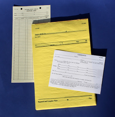
In addition to the above, I also use switch lists, “flimsy” train order forms, and clearance forms, all copied directly from SP originals, as shown below (at the time I model, SP did not put its name on train order or clearance forms). Prototype originals like this can be a starting point if your layout models a fictitious railroad. 

Last, I plead guilty to having contributed to the recent upsurge in interest and usage of prototypical waybills. Having over more than a decade, written 117 posts on the topic (for a guide to the first 100 of these, see this post: https://modelingthesp.blogspot.com/2022/11/waybills-part-100-guide.html ), along with several magazine articles, I can’t hide from it; but I do think this is an obvious feature to include on any layout that has switching. I won’t go further into waybills at this point.

The paperwork items described above are certainly typographic scenery, but more importantly, they are among the tools for prototype operation that follows the prototype. I will turn to that aspect, layout operation, in a future post.

Tony Thompson


Sunday, December 8, 2024

The 14th anniversary of this blog

My first post to this blog was on December 8, 2010, which makes today’s post a completion of 14 years of this activity. As of today, this is the 1730th post in this series, which seems a little unreal to me, but it must be true, because both Google and I keep track, and amazingly, I wrote them all. Whew! Certainly never expected all this back on this day in 2010. 

As I often do in the annual reflections, I have looked at the page view data provided by Google, the host for my blog. In the early years of the blog, it typically received 150,000 to 200,000 page views a year. More recently that has moved above 300,000 a year, and for this most recent year, it is at 385,000 page views. My total for the 14 years is now just a hair above 3 million page views. This is nothing compared to an internet “influencer,” but seems like a fair amount for a model railroading blog. 

The graph below is Google’s data for the past year (you can click on it to enlarge). I have no explanation for the areas of spikes in page views, but one can readily calculate that the daily average for most of these years is in the range of 500 to 1000 views a day. The two numbers at right are the page views (3.01 million) and the number of comments (2753). The drop at far right is because December isn’t complete.

Over the years, I have often received comments and questions in Google’s Blogspot process (that’s the 2.75 K number above), which appear at the bottom of each post, and that’s fine. I do respond to them. I have also frequently received questions or comments by separate email to me personally. Some of those have even generated entire posts in response, which shows that these communications can be quite substantive. They are part of what makes the blogging process interesting and fun for me.

One noteworthy event of the year was my completion of requirements for the Master Model Railroader award of the NMRA. I completed the last three achievement certificates last June, and have now been awarded the plaque as MMR  #772. I offered commentary on this, and showed the biography of me that was published in the NMRA Magazine in November, in a previous post (see it at: https://modelingthesp.blogspot.com/2024/10/personal-master-model-railroader-772.html ).

The plaque was delivered to me in a surprise move at an operating session at Steve Van Meter’s layout. Here is a photo of the operators on the layout that day, with the plaque being held by me and Earl Girbovan, to my left, who is now the Pacific Coast Region’s Achievement Program Manager (taking over from long-time stalwart in this job, Jack Burgess).

From far left, the folks in the photo are: Richard Brennan, Jim Radkey, John Wiley, John Sutkus, me, Bob Osborn, Earl, Mike Stewart, Andy Schnur, Steve, Bob Rosenbauer, and Jeff Allen. The person standing behind Andy and obscured by him is Seth Neumann.

Here is a better view of the plaque itself, alongside my John Allen award from PCR’s Coast Division, as it is placed in my layout room:

Meanwhile, operating sessions on my layout have continued. On the present version of the layout, that is, the one I’ve remodeled and completed here in Berkeley, the most recent pair of sessions (for comments about them, see: https://modelingthesp.blogspot.com/2024/11/my-latest-operating-session.html ),were the 95th and 96th sessions. I continue to feel, as do many layout owners, that the layout really comes to life and best expresses my ideas for it, when visitors operate it under my direction. I hadn’t thought this or expected it, years ago when I started work on a layout, but it’s true. And it definitely is satisfying.

The same remains true for the blog.It’s almost always fun to dream up topics, figure out what’s needed to describe and illustrate them, and then to compose a draft of each one. Sometimes the inspiration just flows, and a draft needs hardly any revision; more usually, a draft may need to be polished and refined numerous times to bring it to what I wanted to say. But it remains enjoyable.

Tony Thompson

Friday, December 6, 2024

Restoring an old Ulrich hopper car

I was recently browsing in my stash of old or unused freight cars, and came across an Ulrich metal hopper car from my teenage years. Among other things, it has Devore couplers in Devore draft gear boxes. The wire grab irons and lettering looked pretty good, so I decided to see what could be done with it — and to check whether it was a model of an actual prototype. Back in those days, there were relatively few commercial freight car models, and many were lettered for pretty much any popular railroad. 

(I have worked on a number of old Ulrich HO scale freight cars over the years, and have reported some of the projects in past blog posts. To find them, if you’re interested, use “Ulrich” as the search term in the search box at right. The Ulrich company, founded in the late 1940s by Charles J. Ulrich, was a mainstay of HO scale modeling the 1950s, and later became part of the Walthers line.)

Below is the model. Aside from the heavy sill steps, cast onto the white-metal car sides, it doesn’t look too bad. The model, unlike Ulrich hopper cars in later years, did not have cast-on grab irons at the right of each car side, but had free-standing Athearn metal ladders, not a bad idea under the “three-foot distance” rule. This is an immediate clue that this is an early Ulrich hopper.

Is this prototype? It sure is. Norfolk & Western built 12,500 cars like this in the 1930s, and the Ulrich model is a definite match. Below is a prototype photo (N&W photo), showing the first of these cars at Roanoke in 1936. You can just see the angled heap shields, just like the Ulrich model. Incidentally, anyone with even a faint interest in coal hoppers should own Bob Karig’s superb book, Coal Cars (University of Scranton Press, 2007), where I found this photo.

In 1953, the year I model, there were more than 8700 cars of these dimensions, though Class HL is not called out separately. That certainly means that an N&W hopper chosen at random might well be a car like this model.

Now I expect that at least some readers will be thinking, “What on earth is he thinking about, coal hoppers in California?” And in some ways, that’s true. But coal was certainly used in a number of ways in California at the time I model, as I discussed in an earlier blog post (see it at: https://modelingthesp.blogspot.com/2018/02/coal-in-california.html ). 

As mentioned in that post, little coal was ever found in California, and none of it very good, a natural result of California’s geologic history (marvelously explained for laymen in John McPhee’s excellent book, Assembling California, 1993). Accordingly, lots of it was imported, usually by rail, and sometimes from far away: thus an N&W hopper could be okay.

For those not familiar with the Ulrich models, they had cast white metal sides, ends, interior braces, and hopper gates, with sheet brass slope sheets. Thus it’s not surprising that the model weighs over 3 ounces, above the NMRA recommended weight for this car length. The model has metal sprung trucks, nice looking but with pre-RP 25 wheel flanges, so I will replace the entire truck.

The familiar Ulrich hopper kit of later years had a cast metal underframe, so that the assembly process would be as shown in the instruction sheet below (from the HOseeker website, https://hoseeker.net/Ulrich.html ). It is clear how the parts go together, and it makes a sturdy model. But this is not my model. (You can click to enlarge if you wish.)

My hopper, instead, happens to be the original Ulrich hopper, which had a pine center sill and balsa bolster/slope sheet supports. It also has applied ladders instead of the cast-on grab irons seen in the directions above. The directions for this somewhat different kit (sides and ends are like the later kits) is shown below (again, HOseeker). The wood parts are in the drawing at the top of the directions.

I will disassemble the underframe parts that support the draft gear, replace the balsa with styrene, and modify to accept a Kadee coupler box. I’ll describe that work in a future post.

Tony Thompson

Tuesday, December 3, 2024

Refining layout scenery, Part 2

In the previous part, I mentioned that no matter how carefully built the layout is, or how conscientiously maintained, careful examination will inevitably reveal a few layout areas that need work. Some time ago I began to be more systematic in this layout examination process, which I have termed “management by walking around” (see the post at: https://modelingthesp.blogspot.com/2018/07/management-by-walking-around.html ). And yes, I know this phrase is already a cliche in management circles.

My first venture back into this process, after some time off, was reported in the first post in the present series, describing an improvement in the location of my yard limit sign at Shumala. You can read that post here: https://modelingthesp.blogspot.com/2024/11/layout-scenery-refinements.html ).

One persistent problem on the layout has been in the area near the mainline tunnel, leaving Shumala westward. Near the tunnel mouth, there is a track gang’s tool house (at right below), a milepost (the telegraph pole with the white paint and the milepost number), a cable box (where telegraph lines from the pole go underground to traverse the tunnel), and a phone booth, all near a ground throw for the Shumala siding. This is a kind of tight location for throwing that switch, especially for those with fat fingers or diminished coordination.

The view above probably looks okay. But I realized long ago that some people would find the ground throw area a little confined, and would bump into the phone booth and cable box, so they aren’t glued down. As a result, after most operating sessions the area shown above looks like what you see below.

The real problem is that there isn’t room to put those two items farther from the ground throw, because the ballasted grade area narrows toward the telegraph pole. The obvious solution is to enlarge that grade down to and past the pole. My method was to mix up a little Sculptamold paper mache and adjust the contours appropriately, as you see here.

Next I painted the new area with acrylic tube paint, Burnt Siena, as a foundation for scenic materials to follow. I had originally planned to ballast the entire new contour, and put the phone booth and cable box back on top of it. But as I mentioned in the first post in this series, this is not what Southern Pacific usually did. They mostly put things like phone booths on the ground outside the ballast. I decided to do the same.

My usual base scenery material for “ground” is a medium tan earth, actually real soil collected around home plate on a softball diamond. I paint the area with dilute matte medium, apply the soil, and spritz it with “wet water,” water with a bit of detergent, this latter to help make sure all the scenic material is contacted by the matte medium. I then add a pinch of ground foam grass, so the ground isn’t perfectly bare. That gives the appearance shown below. Comparing the top photo in the present post, you can see how the level area has been enlarged.

Next I simply replaced the cable box and phone booth, but now much closer to the pole, leaving more space for “fat fingers” to operate the ground throw. These remain unglued for the reason stated above. I have considered adding a heavy cable from the top of the cable box up to the pole, representing the telegraph lines being brought down from the pole to an underground line, but have not decided how best to do this. So for the time being, this is the arrangement.

I have a couple more minor scenery refinements like these to describe, and will do so in future posts. To repeat, these are quite minor projects, chosen only to illustrate that even a fairly complete layout needs continuing attention to scenic details. Perhaps these posts will allow you to look at your own layout with a fresh eye.

Tony Thompson