To obtain sufficiently large access to the car interior, the rivets holding the tank end would be cold-chiseled off, the tank end removed, and the bulkheads placed in the interior. They would then be riveted in place with river rows around the exterior. The interior arrangement might look something like this, with the interior bulkheads shown as dashed lines:
The middle dome may not look like it’s in the car center, but that’s an optical illusion. Here’s an example of an actual car like this, owned by Kanotex Refining (supposedly named for its operations in Kansas, Oklahoma, and Texas), reporting mark KOTX, from Richard Hendrickson’s collection:
My modeling project was stimulated by an article in a very old Model Railroader, part of the Eric Stevens “Dollar Car” project articles. It was originally published in the October 1953 issue of MR (appropriate, I guess, since I’m modeling 1953!), page 44, and was reprinted as Chapter 18 in the Kalmbach book, Easy-to-Build Model Railroad Freight Cars (1971), a compendium of the Dollar Car projects.
This article showed an easy way to scratchbuild an underframe for a tank car using interlocking wood parts. The general idea is sketched below, with the end notches intended to hold coupler boxes. I used basswood, 3/16-inch square, to make the center sill and bolsters. I then used cardstock (literally, from 3 x 5-inch cards) and made overlay strips, which were embossed with rivets made by a row of scriber indents, and made the wood parts look like flanged structural shapes. This underframe is surprising easy to make, and when complete, is impressively strong and rigid. I then scratchbuilt the remainder of the underframe and walkways, and added all the usual brake parts, mostly from wire. (The drawing is adapted from the Stevens article and is used by permission of Model Railroader. The article contains full dimensions of the parts.)
The tank was made from an oak dowel, cut to length and then sanded on the ends to approximate the shape of prototype tank ends. The size was chosen to match an 8000-gallon tank. I then wrapped the tank with 0.005-inch styrene, impressed in advance with rivet rows where needed.
I had an ancient and somewhat beat-up Walthers soft-metal casting of a dome (maybe lead), and after correcting its distorted shape and adding some detail parts, I made a rubber mold of it and cast two domes in resin.
I made handrail stanchions from rivet-impressed strips of 0.005-inch styrene (poor choice, as they are not very sturdy), and used styrene of scale 1 x 4-inch size to make the tank hold-down bands. Here’s the prototype I was aiming at, because I have an Associated Oil Company dealer on my layout. (The photo is from the Jim Gerstley slide collection and was published in Richard Hendrickson and Ed Kaminski’s book, Billboard Refrigerator Cars, Signature Press, 2008.)
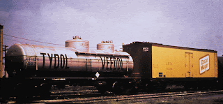
Tidewater Associated Oil Company, parent of Associated in the 1950s, owned several compartment cars like this. Their car number series from 551 to 590 was all compartment cars of 8000-gallon capacity. “Tydol” and “Veedol” were Tidewater trade names for both gasoline and lubricants. Note that this car has a smaller dome on the added compartment, a logical arrangement since that compartment is smaller than the original full car, though the Kanotex car shown above appears to have two identical domes (both Kanotex domes might be replacements). I went ahead and used my two identical domes on my model.
Lettering was accomplished mainly with Champ decal set HT-220, for Tydol-Veedol tank cars, though some of the detail lettering was oversize and was replaced from other sets.
Here is the completed model, photographed on C.J. Riley’s old layout:
Tony Thompson


Tony,
ReplyDeleteBetween all these great articles on tank cars on your blog and the article in RMC for July (arrived yesterday) you have moved the modeling of tank cars into the forefront of the hobby. Thanks for those of us who love the movement of liquids prior to the pipelines and of course the Espee was up in the lead on both the tank cars and the pipelines.
Thanks,
Tom VanWormer
Monument CO
Thanks for the kind words, Tom. Just remember, some of us love the movement of liquids even AFTER there were pipelines .
ReplyDeleteTony Thompson
Good post! Thanks for sharing this information I appreciate it.
ReplyDeletePeugeot Clutch repair & Porsche Clutch repair